
InspectAPedia® FREE Encyclopedia of Building & Environmental Construction, Diagnosis, Maintenance & Repair |
Question? Just ask us! InspectAPedia
|
 Air Conditioning Refrigerant Line Installation Procedure
Refrigerant Piping
Specifications & Piping Mistakes to Avoid
- POST a QUESTION or COMMENT about HVAC system refrigerant piping or tubing routing, connections, materials, charging
Refrigeration equipment piping for air conditioners & heat pumps:
This air conditioning repair article discusses the refrigeration piping requirements, insulation, mechanical fastening, and allowable distances as well as errors in air conditioning refrigerant piping installations that risk future refrigerant leaks or malfunction in the cooling equipment.
Discussed here: Refrigerant line insulation requirements & common temperatures; Refrigerant line mounting requirements & mechanical damage risks;
Air conditioning refrigerant piping distances and diameters required; Allowable distances between air conditioning compressor and air handler;
Why & where you will see refrigerant line brazing or soldered together at the Low Pressure & High Pressure lines. Specifications for buried refrigerant piping or lines.
InspectAPedia tolerates no conflicts of interest. We have no relationship with advertisers, products, or services discussed at this website.
Air Conditioner Refrigerant Line Installation Requirements & Refrigerant Line Defects
 According to Carson Dunlop Associates Home Reference Book,
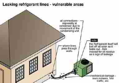
The copper refrigerant lines move the refrigerant between the condenser and the evaporator. Refrigerant lines are normally arranged in pairs, with the larger diameter line carrying gas and the smaller one carrying liquid.
The larger refrigerant pipe containing cool gas is typically insulated to prevent condensation and increase efficiency.
The most common problems with refrigerant lines are mechanical damage, leakage and corrosion. Refrigerant lines are frequently damaged where they pass through the house wall.
Leaking refrigerant lines are usually identified by oil deposits on the line.
Illustration, above left, courtesy of Carson Dunlop Associates, a Toronto home inspection, education & report writing tool company [ carsondunlop.com ]. [Click enlarge any image]
Article Series Contents
- REFRIGERANT PIPING DAMAGE & LEAKS
- REFRIGERANT PIPING GURGLING
- REFRIGERANT PIPING INSULATION
- REFRIGERANT LINE MOUNTING
- REFRIGERANT LINE NAIL PROTECTION - protect refrigerant piping from damage by nails, screws, structural movement
- REFRIGERANT PIPING LENGTH vs DIAMETER
- REFRIGERANT TUBING BRAZING & SOLDERING
- REFRIGERANT TUBING FLARE CONNECTIONS
- REFRIGERANT TUBING ECONOMIZER & HEATING TRICKS
- REFRIGERANT PIPING UNDERGROUND, BURIED
- REFRIGERANT PIPING CODES & STANDARDS
Causes of Refrigerant Piping Damage & Leaks
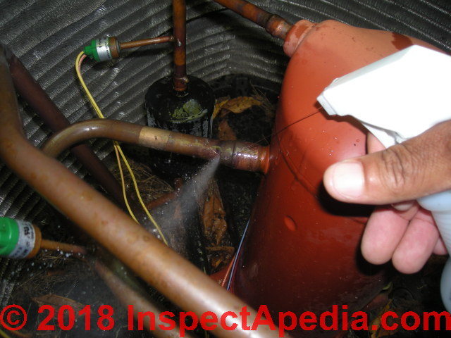 The refrigerant piping leak shown in our photo - provided by an InspectApedia.com reader - is discussed in detail
at REFRIGERANT LEAK REPAIR FAQs
Common sources of damage to refrigerant piping that results in refrigerant leaks and of course need for repair include at least the following:
- Inadequate support of refrigerant piping
can expose refrigerant piping to movement and damage that we cite in more detail in the rest of this list. - Mechanical impact damage to refrigerant tubing:
air conditioning & heat pump or other refrigeration equipment that is exposed to damage by movement of vehicles, tools, or other activity can lead to bends, kinks, or breaks in refrigerant tubing or piping. - Mechanical damage to refrigerant piping from movement:
such as settlement of a compressor/condenser pad at an installation lacking a flexible loop of refrigerant piping - as is more-likely to be the case with larger-diameter piping. - Perforation damage of refrigerant lines:
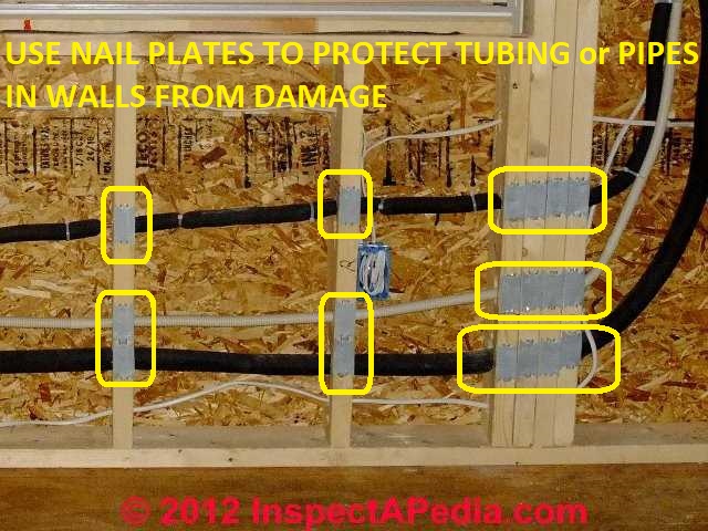
refrigerant lines routed through building framing too close to wall surfaces and without the required nailing plates exposes the piping to perforation later when someone drives a nail or screw into the building wall (or other surface).
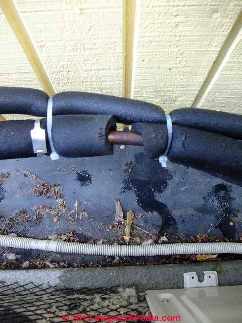
Our photo at above/left shows steel nail protection plates that we installed to protect both the refrigerant piping lines (insulated in black foam) and the condensate drain line (between the two black insulated refrigerant lines). - Vibration damage to refrigerant piping:
vibration can cause heavy, poorly-supported components to bend or break refrigerant lines and brazed connections. - Vibration / rubbing damage to refringerant tubing:
vibration combined with contact between a refrigerant line and another component can cause abrasion and wear-through of the refrigerant tubing or piping - Improper original installation of refrigerant piping or bad braze joints:
poorly-made braze joints in refrigerant piping can lead to later breaks, equipment damage, or refrigerant leaks due to
Ridging in the swage joint made to enlarge tubing as needed to match its connecting fitting
Over-thinned copper at the swage joint
Overheating of and oxidized copper at the braze joint
Corrosion of copper tubing from excessive flux or brazing metal
Contamination of refrigerant tubing interior from ozidized copper, flux, brazing compound, and possibly refrigerant oils and refrigerant gases if the system was not properly evacuated
Contamination of refrigerant tubing interior with metal flakes or other debris when high temperature brazing is performed without flushing the lines with nitrogen before & during brazing/ soldering
Note that contaminants introduced in the refrigerant piping system during brazing can lead to future compressor, TEV, or other component failure if not properly intercepted by filter/drier canisters
See also REFRIGERANT DRIERS & FILTERS - Length mistakes in refrigerant piping:
failure to leave enough slack or bends in refrigerant piping can lead to mechanical damage and leaks as outdoor equipment may move or settle. - Perforation of refrigerant tubing by nails or screws:
piping penetrated by nails or screws driven into the building wall studs or other framing where proper protection of the tubing was omitted (nail plates) - Electrical arcs, currents, shorts to the refrigerant piping:
can damage refrigerant piping as we illustrate in a reader discussion and with photographs below.
The source of electrical damage to refrigeration equipment including refrigerant piping, condensing or cooling coils, and heat exchanger coils in water-to-air heat pump systems may originate in- A lightning strike or power surge causing electrical arcing in or around the HVACR equipment
- A component failure in the air conditioner or heat pump or other refrigerant system that causes electrical arcing
- Improper original electrical wiring that creates stray currents
- Improper electrical grounding and un-anticipated current flow through other metal components or piping in the refrigeration system
An example of arc damage to copper piping is shown below.
- Use the page top or bottom CONTACT link to send us a note if you know of other sources of electrical or other damage to refrigeration piping systems
Question: cause of a perforation leak in a refrigerant piping line
 2016/08/23 Jon said:
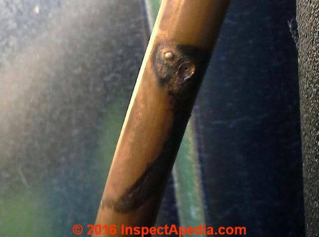
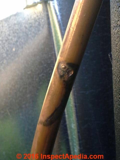
I had a refrigerant return pipe blow a small hole (about 18 months after install). It turned out the copper pipe as touching the aluminium cover that had been attached on top of the pipe run in this one place.
I could see copper had deposited itself on the aluminium inside the cover which looks due to possible galvanic corrosion over time - but the blow out was a pin hole which, it is surmised, was due to electrical current running down from a lightening strike.
It seems clear to me the copper pipe should not have been touching the cover, it only did so in this one place. It must have been protruding some obvious distance to touch the cover when this was installed. Would I be correct that this was an install error?
(mod) said:
Thanks for this note, Jon. Indeed there could be a galvanic corrosion problem when aluminum is touching copper; such leaks also occur not just from a lightning strike but also from improper electrical grounding of the equipment and sometimes from vibration rubbing the two components together.
Use the page top or bottom CONTACT link to send me some whole unit and then closeup photos of the situation and we can comment further.
2016/08/25 Anon wrote [by email to editor]
Thanks for your posted response regarding the install I have where they left the copper refrigerant return pipe touching the inside of the aluminum protective cover at one place.
The pipe blew out at this point. The guess is electrical current caused this. As I suspected, the pipe should have been clear of the cover as there is risk of galvanic corrosion and friction damage. Now if appears the touching is the reason for an electrical arc?
There was no sign of scorching on outside of cover - only the black streaks showing in picture on pipe. I never saw the pipe, only the cover, and this picture has just been provided by engineers.
You mention possible electrical grounding issue as a reason? There is no sign anywhere on house of an electrical strike - i am no expert but might expect to see some scorching somewhere.
So if an electrical arc the current must have run down copper pipe and arced where the two metals made contact. There was a copper deposit on inside of the cover where they had touched.
Your opinion on what logically appears to be an install fault due to touching pipe and cover is very appreciated. If this could also denote a grounding issue that info is also appreciated.
Reply:
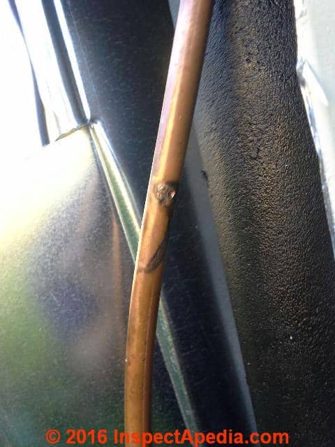
The pitting and crater and black marks look a lot like an electrical arc, not a vibration wear-through.
Also see REFRIGERANT LEAK REPAIR
Reader follow-up:
Yes electrical arc does seem most likely. I do believe the proximity of the pipe touching the casing allowed the arcing to happen at this point - and there should not have been a point where the two touched - I believe am correct in saying this?
Where the electrical current came from is unexplained. Lightening is offered as an explanation but no sign of any strike anywhere.
E,g The casing was clean all the way up - no scorching. Should I be looking for a possible electrical fault connected to the AC equipment.
Moderator reply:
Yes certainly. I'd start by a visual inspection of the equipment for a loose wire, connection, or component, and also I'd look for burn marks or overheating signs inside the equipment.
From your photos I lack a more distant perspective view (send that along if you can) that might be informative.
Refrigerant Line Mounting Requirements
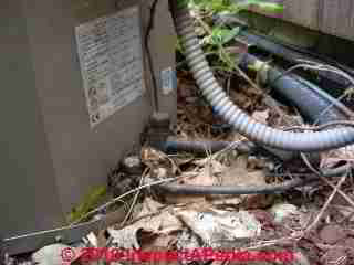
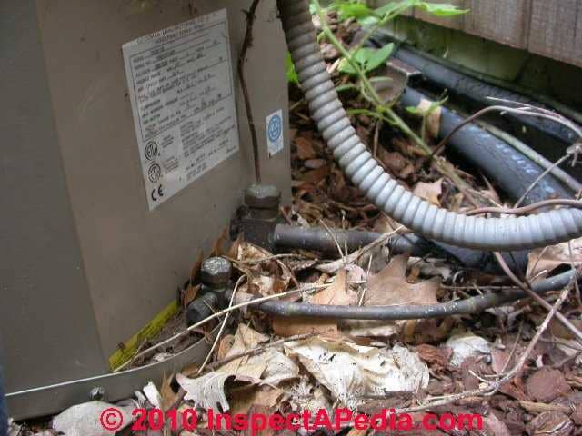
Absence of slack in the air conditioning system coolant lines at the compressor units can cause leaks: should the compressor move, perhaps because its supporting pads settle, there will be likely leaks at these lines.
You should review this question with your HVAC service person. This item may be deferred until next maintenance or service.
Our refrigerant line photo (below left) shows worn insulation and a crimped condensate drain line.
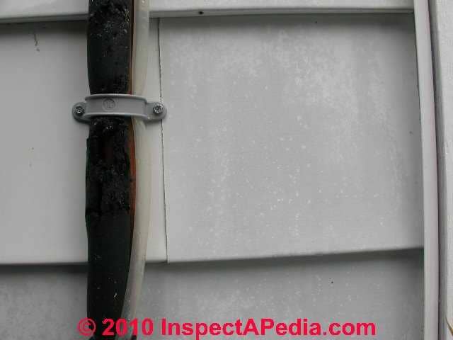
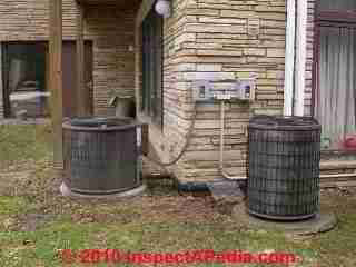
Our photo of a pair of outside compressor units (below) shows what looks like a neat installation, but the mounting of the refrigerant piping against the building wall and absence of slack is just asking for a refrigerant leak in these systems.
Carson Dunlop Associates' sketch illustrates the installation of the refrigerant suction and liquid lines and points out that the refrigerant lines should slope downwards towards the condensing unit - a detail that helps direct refrigerant oil back towards that component.
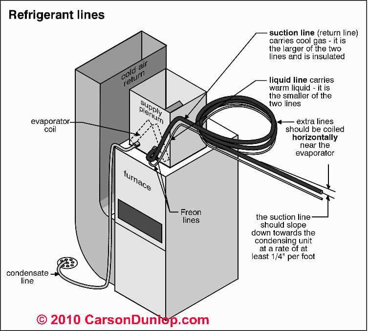
Also notice that the extra length of refrigerant piping that may be found both indoors at the air handler and outdoors at the condenser / compressor unit should be coiled and positioned properly as well.
According to McQuay International, a large producer of refrigeration equipment,
Refrigerant lines need to be securely installed to minimize vibration that causes noise and damages piping.
Reciprocating compressors, in particular, cause vibration. Steel braided flexible refrigerant lines (a must for spring isolated reciprocating compressors) minimize this vibration. ...
Refrigerant lines that rub against solid objects wear holes through copper and create a leak. For this reason, when refrigerant lines pass through walls, the line should pass through sleeved openings in such a manner that the lines do not touch.
There are several commercially available pipe clamping systems that allow pipes to be held rigid without causing damage to them. Most include some form of rubber grommet around the pipe, which is then secured within a bracket. Many building codes specify minimum support spacing.
Piping should also be protected from mechanical damage.
Where piping is exposed to possible damage, the lines should be routed out of the way or be protected in some form of chase.
Burying refrigerant lines should be avoided. [6]
Refrigerant Line Installation in Buildings: Nail Protection Requirements
Use Nail and Screw Plates to Protect Refrigerant Tubing

Where refrigerant piping (or condensate drains) are routed through building walls, floors, or ceilings, if the holes drilled through framing members place the tubing too close to an interior or exterior wall surface, there is a risk that a drywall nail or screw, or an exterior siding nail will puncture the refrigerant lines.
We protect against this hazard by nailing standard nail plates across the face of each stud, joist, or rafter where this risk is present.
Our refrigerant line photo (left) shows liberal use of these nail plates on the interior face of wall studs where the routing of refrigerant lines was close to the interior wall surface.
Because the builder had not yet completed the exterior siding (just the OSB sheathing was in place), we also had to watch out for use of long siding nails that might puncture one of these lines.
Outside the building in areas where this was a concern, because the sheathing was already in place, we simply marked "no-nail" areas on the OSB.
Protection plates, or nail plates are described and their use detailed in
- Simpson Strong-tie 2020 CODE-COMPLIANT REPAIR & PROTECTION GUIDE for the INSTALLATION of UTILITIES in WOOD FRAME CONSTRUCTION [PDF] (2020) Recommendations for the construction of building-code-compliant decks, Simpson Strong Tie®, retrieved 2020/11/23, original source: https://www2.strongtie.com/catalog_order.asp?site=SST where you can download any of a large collection of reference documents, catalogs, and product guides from Simpson Strong-Tie.
Refrigerant Line Insulation Requirements & Proper Installation Details
Refrigerant piping should be insulated. Manufacturers also recommend wrapping the insulated refrigerant lines exposed to outdoor weather, using an appropriate weatherproof tape.
For details about proper installation of insulation on HVACR refrigerant lines or piping please
see REFRIGERANT PIPING INSULATION.
Crimped Refrigerant Line or Tubing Insulation
Air conditioner manufacturers include installation instructions with each unit.
It's worth taking the time to read all of those details as the manufacturer has the same desire for a successful and trouble-free installation as the home or business owner or the HVAC installer.
Among these instruction details you'll read how the manufacturer wants the refrigeration lines installed, including the following:
When installing insulation over the refrigerant tubing, do not over-tighten the foam insulation (typically held in place with plastic ties or tape). Crimping the insulation along its refrigerant tubing pathway creates points of less and possibly inadequate insulation.
Missing or inadequate refrigerant piping insulation means a system that operates at a lower efficiency and it risks condensate drips into problem areas such as wall or ceiling cavities - a mold risk.
Air Conditioner Refrigerant Line Diameters & Lengths vs. Distance Between Compressor/Condenser and Air Handler/Evaporator Coil
How Far Apart Can I Separate the Air Conditioner Compressor/Condenser from the Air Handler/Evaporator Unit?
I live in a townhouse and have a split air conditioner system. The compressor is currently on the roof, but it may need to be relocated to ground level. The other unit is in the attic. How far away from the house can the compressor be (maximum, not minimum).
I do not want to put the unit on my terrace, which is next to the house, because it would diminish our ability to use the terrace due to noise, etc. Could the unit be located approximately 37 feet away from the house without affecting it's function? This would place it at the back of the garden, either behind a fence or obscured by a shrub. - Anon.
Answer: Almost any A/C equipment separation distance can be made to work, but the installer will need to take a look at refrigerant piping diameter guides
Moving an air conditioner compressor to a distance of about 40 feet from a building wont' prevent it from working, but the installer might need to adjust the diameter of the refrigerant lines to be sure that the equipment is working at 100% of its capacity.
A more careful answer to your question is not so much that there is a specific distance limit between the A/C compressor and A/C evaporator coil so much as a need to get the size (diameter) of refrigerant lines and amount of refrigerant charge correct - that is, if we exceed some distance, probably like 100', we may need to increase the refrigerant piping diameter as well as the refrigerant charge for the system to work properly.
There is a more subtle technical concern with refrigerant velocity in the line. If the velocity is too low, refrigerant oil may not be properly distributed in the system. In addition to total length of refrigerant piping, the number of elbows, bends, fittings, also affect flow and have to be taken into account.
Each A/C manufacturer offers their installer technicians equipment installation instructions that include how to size refrigerant piping properly. The instructions may include complex calculations, or simply a chart of separation distances between the outside compressor/condenser unit and the inside air handler/evaporator unit.
If there is not a "table" of distances and pipe diameters for a specific air conditioning system, then the manufacturer will expect the installer whose layout is different from the usual distances to make some measurements on the system and to adjust it accordingly.
Diameter of Refrigerant Piping & Tubing
In a nutshell, the size in diameter of the refrigerant suction and supply piping needs to be determined by the installer based on the distances involved, the equipment tonnage, changes in elevation between compressor and evaporator coil, the number and type of fittings in the refrigerant piping system, ambient operating temperature ranges, and other cooling equipment specifications given by the manufacturer.
If the installer places the equipment far enough apart that s/he should have used a larger (or smaller) diameter piping system, the A/C system will still work, but its cooling capacity may be reduced.
A cooling line that is too big in diameter OR too small in diameter can cause the equipment not to work properly or efficiently.
Copper Tubing ID versus OD: internal diameter versus outside diameter
It's easy to get confused about pipe sizes or diameters when discussing flexible copper tubing.
Refrigeration technicians often refer to flexible copper refrigerant tubing by its outside diameter or "OD" while plumbers usually refer to any piping by its inside diameter or "ID".
A 1/4" OD (outside diameter) flexible copper refrigerant line actually has about a 1/8" ID (inside diameter).
So when you are measuring or ordering piping, make sure you and your supplier are talking about the same size by using "OD" or "ID" in your measurements.
Storage of Refrigerant Piping or Tubing
Unused refrigerant piping or tubing should be stored with its ends capped to keep dirt and moisture out of the piping.
Refrigerant Piping or Tubing Connections
Most HVAC systems that we have inspected and all that we have installed or repaired used soldered or brazed connections for copper refrigerant piping on both suction and high pressure lines.
Some manufacturers, codes, and procedures also allow flare fittings - something we have used on some LP gas lines but in our OPINION flare fittings are more leak prone than soldered connections. (We do not use compression fittings on refrigeration and air conditioning systems.)
Soldering or Brazing Copper Refrigerant Tubing or Capillary Tube Connections
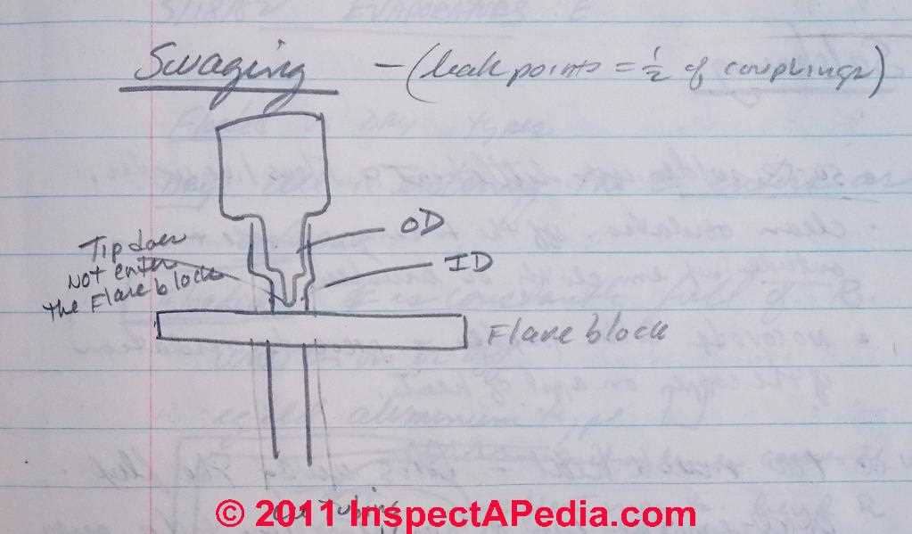
In the opinion of some HVAC instructors, half of the leaks found in refrigerant piping are traced to defective soldered or flared connections so it's important to make these connections as close to perfect as you can during system installation or repair. [1]
Sections of flexible copper tubing to be soldered or brazed together are connected using a procedure called swaging.
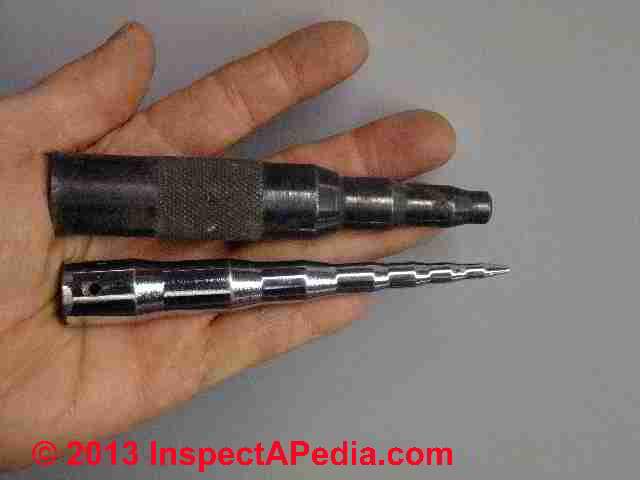
A swaging tool (see our sketch above and our photograph at left) is used to join similar-sized sections of refrigerant piping without requiring an additional coupling fixture. Swaging tools come in a range of sizes - two of mine [DF] are shown at left.
Typical swaging tools used for refrigerant piping connections handle tubing sizes 3/16", 1/4", 5/16", 3/8", 1/2" and 5/8" O.D. (Refrigerant tubing sizes are specified in O.D. or outer diameter).
The advantage of this approach is that we eliminate at least one soldered joint, increasing the reliability of the refrigerant piping system (or other piping) against leaks.
The swaging tool is inserted into the end of the copper tubing through a flare block or, if the installer is experienced, the tubing may be hand-held.
The swaging tool is carefully hammered until it has expanded the copper tubing internal diameter (ID) sufficiently to permit it to slip over the connecting copper tubing section.
The interior of the enlarged end of tubing and the exterior of the factory-sized tubing that will insert into the enlarged mate are both cleaned, primed, or fluxed and soldered according to the manufacturer's instructions, typically using silver solder, or in some applications, brazing.
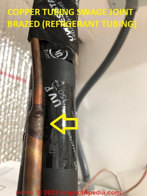
Special thanks to InspectApedia.com reader (anonymous) for the photo of a copper tubing swage joint, shown above. 2022/10/24
Watch out: improper swaging can damage copper tubing leading to future failures and leaks.
- If the swaging tool is not held straight the swage may be askew, or uneven in thickness leading to future tubing failure or leaks
- If hammering is not done consistently a ridge can form in the swage leading to a future leak
- If the tubing is over-thinned there is greater risk of a future failure from vibration-breakage or corrosion penetration of the tubing.
Guide to Brazing or Soldering Materials & Temperatures for Refrigerant Piping & Tubing
This article describes three different temperature ranges for soldering copper piping or tubing along with some general copper pipe or tubing soldering advice.
General Soldering Advice for Copper Piping or Tubing
- Clean oxidation off of the copper tubing inside and outside before soldering, using emery cloth or wire brushes.
Meticulous cleaning is necessary to get reliable solder connections and leak proof joints. - Use anti-corrosion soldering paste or flux - choose the proper flux for the type of connection, soldered vs. brazed.
Brazing is a much hotter method than soldering, so requires different materials.
The use of brazing flux or soldering paste prevents oxidation of the copper surface when you heat the tubing or piping in the course of soldering the materials together. - Don't use more heat than necessary to make a soldering connection.
Too much heat boils away the flux and oxidizes the copper. If you see this happening you'll have to stop, cool the copper tubing or piping, and start over at the cleaning step.
Temperature Ranges of Copper Soldering
- 300 deg F copper soldering:
uses a 50:50 solder that requires little heat. The solder flows like water - it's easy. (50:50 lead solder is no longer used in plumbing applications out of concern for lead in water supplies). - 500 deg F copper soldering:
using 95:5 solder to get more heat to get the solder to flow.

- 1150 deg F copper soldering:
silver solder, use on big refrigeration systems, use when there are wide temperature variations (to withstand the expansion/contraction);
can cause flaking inside the copper line, so in refrigeration applications, good practice flush the lines with nitrogen and flush them with nitrogen too while soldering; silver soldering is also used when there are variations between the two metals joined, e.g. steel to copper.
The joint has to be red hot. Watch out to avoid using this process too close to 95-5 solder joints or they will melt.
The copper tubing ends to be connected are cleaned, sanded, treated with soldering or brazing flux, and soldered or brazed.
When a capillary tube is to be soldered take are not to place soldering flux too far into the joint or the solder may flow over and close the end of the capillary tube. (see our sketch).
Advice for Making Flare Fitting Connections with Copper Tubing or Piping
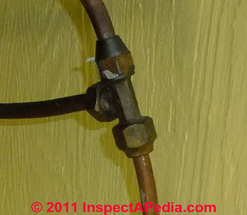
Watch out: in our OPINION (and that of other HVAC technicians) compression fittings should never be used and in best practice flare fittings should also not be used on refrigerant gas or liquid piping. Soldered connections are much less likely to leak under the harsh conditions to which refrigerant piping is subjected: vibration, high pressures, high temperature swings, and outdoors, weather exposure.
- When you cut copper piping or tubing using a saw (rare) or a copper pipe or tubing cutter (the usual practice) the cutting wheel may leave a lip of copper on the inside of the copper pipe or tubing.
For soldering or flaring copper piping, you will want to remove this lip (to be sure that the full diameter of the pipe is available to avoid a flow restriction, and when making a flare fitting in particular, be sure also to remove burrs in the copper pipe or tubing end before attempting to create the flare end of the tubing using your flaring tool.
Plumbing and HVAC supplies sell special reaming tools used for this purpose. Don't over-do the reaming or you may create an over-thinned tapered edge of your flare that will crack during expansion, but be sure that all burrs are removed. - Put the flare nut onto the tubing before making the flare - you'll only make this mistake once.
- For 1/4" OD tubing, the end of the tube extends about 1/8" above the flaring block at the start of the flaring procedure.
- The flare that you create should fit snugly inside of the nut, extending to fully cover the tapered seat inside the nut, and it should exactly cover the face of the flare fitting.
- Also see "Identifying Sources of Leaks at Brass Flare Fittings ..." found
- at GAS LEAK DETECTION, LP / NG where we illustrate examples of causes of leaks in flare fitting connections
Refrigerant Piping Sizing and Run Length: refrigerant pressure drop and temperature loss
For example, measuring the refrigerant gas line pressure drop (or temperature change) on the suction line (return to the compressor) will show (typically) that a 4 degree temperature loss through the refrigerant line will result in an 8 percent loss in cooling capacity of the system.
Or on the discharge line (output from the compressor) will show (typically) that a 4 degree temperature loss through the refrigerant line will result in a 2 percent percent loss in cooling capacity of the system.
So it's not that the air conditioner won't work at all if the compressor/condenser is located at an unusual distance from the air handler/evaporator coil, it's more that it may lose some capacity and have to work harder - meaning higher electrical bills and in extreme cases, shorter equipment life.
Equivalent Refrigeration Piping Length to Include Fittings, Controls Devices
ASHRAE[7] and some air conditioner manufacturers such as McQuay[6] provide a refrigeration piping guide that gives complete, detailed guidance and charts on refrigerant line sizing (diameter) as a function of length of run. The company points out that the entire liquid refrigerant line is composed of more than just piping, and includes
- The length of refrigerant piping itself
- The elbows or other fittings used to joint refrigerant piping between the cooling coil/evaporator and the compressor/condenser unit
- Any filter driers installed (one or in some cases two)
- Any isolating devices, control valves, etc.
Each of these devices or components contributes volume to the refrigerant piping system and must be considered in designing the "equivalent length" of the entire refrigerant piping system in order to determine the proper refrigerant charge. For example,
- A 1/2" nominal diameter globe valve or solenoid valve contributes an equivalent of 17 feet of refrigerant piping
- A 1/2" nominal diameter filter drier contributes an equivalent of 12 feet of refrigerant piping
- A 1/2" nominal diameter suction line filter contributes an equivalent of 15 feet of refrigerant piping
Refrigerant Line Heaters & Economizers
Technical Note on Refrigerant Piping: HVAC economizer detail using refrigerant line brazing or soldering together of the Low Pressure & High Pressure lines for deliberate heat exchange
In some refrigeration system designs, a low-temperature (heat laden) vapor line (suction line) is soldered alongside the high-temperature, high-pressure liquid refrigerant line. This conjoining of the two refrigerant lines is likely to be done where the vapor line is entering the compressor/condenser unit.
The purpose of this line-to-line soldering is to act as a heat exchanger, to reduce the temperature of the liquid refrigerant that is going to enter the metering device (TEV or cap tube), gaining some benefit to system operation - we want a lower refrigerant temperature at the point where the liquid refrigerant is about to be metered or released into the cooling coil (evaporator coil in the air handler).
A second benefit of this heat exchange is that in the larger suction line entering the compressor, the refrigerant enters at a higher temperature, easing the compressor's job of compressing and raising the refrigerant temperature on the condenser side, so that the refrigerant is (by being hotter) better able to transfer heat to ambient air in the environment around the condensing coil.
Other forms of air conditioner and heat pump economizers and economizer tricks of the trade are discussed
at AIR CONDITIONING HEAT PUMP SAVINGS
Buried or Underground Refrigeration Piping Standards, Codes, Specifications
Buried or underground refrigerant piping on residential HVAC systems is not recommended, but at least for some manufacturers and building codes, underground refrigerant distribution piping is not expressly prohibited, but where used it must be properly installed, protected,& insulated.
Details are at REFRIGERANT PIPING UNDERGROUND, BURIED
Refrigerant Piping Codes, References, Standards
- Allied, REFRIGERANT PIPING DESIGN & FABRICATION GUIDELINES [PDF](2011) Allied Commercial, gives refrigerant piping limits, recommended components, quick refrigerant piping selection charts for the liquid line and the vapor line (suction line), requirements for long refrigerant line piping, fundamental refrigerant piping theory, and details of refrigerant line sizing.
- ASME, Refrigeration Piping and Heat Transfer Components
B31.5 - 2019 - available from the American Society of Mechanical Engineers (ASME) https://www.asme.org/ ISBN 9780791873144
ASME B31.5 covers refrigerant, heat transfer components, and secondary coolant piping for temperatures as low as -320°F (-196°C), whether erected on the premises or factory assembled. Users are advised that other piping Code Sections may provide requirements for refrigeration piping in their respective jurisdictions. - BURIED REFRIGERANT PIPING - UNDERGROUND INSTALLATION GUIDES & PRODUCTS [web page]
- CALIFORNIA MECHANICAL CODE, CHAPTER 11, CMC (2010), [PDF] IAPMO, retrieved 2018/03/13 original source: http://www.iapmo.org/California%20Mechanical%20Code/Chapter%2011.pdf
Excerpt:
1111.6 Underground Piping. Refrigerant piping placed underground shall be protected against corrosion. - Carlyle MINIMIZING REFRIGERANT LINE VIBRATION [PDF] (2021) Carlyle's recommendations to minimize refrigerant line vibrations
Excerpts:
The following bulletin will assist equipment manufacturers in the design of refrigeration and air conditioning systems to minimize refrigerant line vibration problems.
Vibration problems can often result in broken refrigerant lines.
Causes of vibration in discharge lines can be primarily separated into the following categories:
1. Structural Resonances
2. Forced Vibration
3. Acoustical Resonances
Of the above causes of vibration, structural resonances are the most common cause followed by forced vibration and acoustical resonances.
Also see CARLYLE HVACR COMPRESSORS - see also CARRIER - Daikin, REFRIGERANT PIPING DESIGN GUIDE [PDF] (2019) Daikin Applied, Web: www.daikinapplied.com Tel: 800-432-1342
Excerpts:
This Application Guide was created for design engineers and service technicians to demonstrate how to size refrigerant piping.
This Guide covers R-22, R-407C, R-410A, and R-134a used in commercial air conditioning systems. It does not apply to industrial refrigeration and/or Variable RefrigerantVolume (VRV) systems. - International Mechanical Code (IMC) 2021, CHAPTER 11 REFRIGERATION as adopted by various U.S. states or cities.
Eg. New York City Mehancical Code Chapter 11, retrieved 2022/08/24, original source: https://codelibrary.amlegal.com/codes/newyorkcity/latest/NYCadmin/0-0-0-95229 - Johnson Controls, GENERAL PIPING RECOMMENDATIONS AND REFRIGERANT LINE Length for Split-System Air Conditioners and Heat Pumps" - Application Data Sheet [PDF], Johnson Controls Unitary Products, 5005 York Drive Norman, OK 73069 USA, Website: http://www.johnsoncontrols.com/, officesd world-wide, retrieved 2018/03/12, original source: http://www.usair-eng.com/pdfs/long-line-piping.pdf
- Lennox, LENNOX REFRIGERANT PIPING DESIGN & FABRICATION GUIDELINES, [PDF] (2008), retrieved 2018.03/12, original source: http://www.mechanicalconceptsllc.com/downloads/Refrigerant%20Piping%20Manual.pdf
- LG, BEST PRACTICES for LG HVAC REFRIGERANT PIPING INSTALLATION [PDF] (2020) LG Electronics, U.S.A., Inc. Commercial Air Conditioning Division 4300 North Point Parkway Alpharetta, Georgia 30022 www.lghvac.com
- Mitsubishi, UNDERGROUND INSTALLATION of CITY MULTI® R2-Series, Y-Series & S-Series Refrigerant Piping, [PDF] (2002 & 2013), Mitsubishi Electric, retrieved 2018/03/13, original source: http://meus1.mylinkdrive.com/files/ Application_Note_2002_-_Buried_Refriegerant_Lines.pdf
- [2] MODERN REFRIGERATION & AIR CONDITIONING, [Book recommendation] A. D. Althouse, C.H. Turnquist, A. Bracciano, Goodheart-Willcox Co., 1982
- [3] PRINCIPLES of REFRIGERATION, [Book recommendation] R. Warren Marsh, C. Thomas Olivo, Delmar Publishers, 1979
- Puron, RESIDENTIAL [REFRIGERANT] PIPING & LONG LINE GUIDELINE [PDF] (2009)
- [4] REFRIGERATION & AIR CONDITIONING TECHNOLOGY, 5th Ed., [Book recommendation] William C. Whitman, William M. Johnson, John Tomczyk, Cengage Learning, 2005, ISBN 1401837654, 9781401837655 1324 pages
- [6] REFRIGERANT PIPING DESIGN GUIDE [PDF] , [PDF] McQuay Corporation, Americans HQ: 13600 Industrial Park Blvd., Minneapolis, Minnesota 55441, 800-432-1342 (Toll Free) 763-553-5330 (Direct), 763-553-5177 (Fax). Web search 07/15/2010 original source: http://www.mcquay.com/mcquaybiz/literature/ lit_systems/AppGuide/AG_31-011_120407.pdf - q
Excerpt:
McQuay International delivers engineered, flexible solutions for commercial, industrial and institutional HVAC requirements with reliable products, knowledgeable applications expertise and responsive support.
As part of Daikin Industries, a Fortune 1000 company, McQuay is the second largest air conditioning, heating, ventilating and refrigeration company in the world. - Trane, REFRIGERANT PIPING MANUAL for SMALL SPLIT COOLING & HEAT PUMP SYSTEMS [PDF] (2011), Trane Corporation, retrieve 2018/03/13, original source: http://www. ductwork installation .com/ portals/0/ss-apg006-en.pdf
- Trane, REFRIGERANT TUBE SIZE & COMPONENTG SELECTION for RAUC Split Systems (20–120 Tons) Application Guide [PDF] (2001), Trane Corporation, Website: http://www.trane.com/, retrieved 2018/03/13, original source: http://www.trane.com/ Commercial/Uploads/Pdf/1109/large%20splits%20-%20 marketing%20guide%20tube%20size.pdf
- TRANE AIR CONDITIONING REFRIGERANT PIPING MANUAL [PDF] (2011), Trane Belgium, retrieved 2018/05 25, original source: http://www.tranebelgium.com/files/book-doc/20/en/20.aqerykdx.pdf
Trane is an Ingersoll Rand brand. - [7] ASHRAE Handbook, Refrigeration, Chapter 2, 2006. © American Society of Heating, Refrigerating and Air-Conditioning Engineers, Inc., www.ashrae.org.
Reader Comments, Questions & Answers About The Article Above
Below you will find questions and answers previously posted on this page at its page bottom reader comment box.
Reader Q&A - also see RECOMMENDED ARTICLES & FAQs
On 2022-08-24 by InspectApedia-911 (mod) - refrigerant piping routed up against the underside of roof decking is improper
@Anonymous by private email,
1. It is proper for roof nails to penetrate the roof deck:
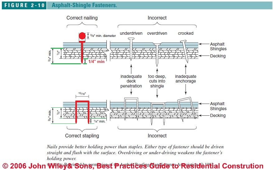 It is proper roofing practice for asphalt shingles and some other roof coverings to use fasteners that are of sufficient length to penetrate through the roof sheathing.
That nail or staple length is required in order to assure adequate holding power - the full-diameter portion of the nail shank must have adequate contact with the roof deck. Here's a code-excerpt example:
- Dixon, Craig Robert, THE WIND RESISTANCE OF ASPHALT ROOFING SHINGLES, [PDF] (2013 Dissertation thesis), University of Florida, retrieved 2017/09/27, original source http://ufdc.ufl.edu/UFE0046235/00001,
Excerpt:
Florida Building Code (2010), Building Commission 2010) requires that fasteners should consist of:
Galvanized steel, aluminum or copper roofing nails, minimum 12 gage [0.105 in (3 mm)] shank with minimum 3/8 in (10 mm) diameter head, ASTM F 1667, of a length to penetrate through the roofing materials and a minimum of ¾ in (19 mm) into the roof sheathing.
Where the roof sheathing is less than ¾ in (19 mm) thick, the fasteners shall penetrate through the sheathing.
Florida Building Code also requires a minimum of four fasteners per strip, and, where the structure is within the High-Velocity Hurricane Zone (Broward and Miami-Dade, FL counties), a minimum of six nails are required (Florida Building Commission 2010). Fasteners are either placed by hand or pneumatic air pressure guns. - Illustration above used in ASPHALT SHINGLE INSTALLATION with permission from Best Practices Guide to Residential Construction, chapter
on BEST ROOFING PRACTICES documents that same shingle nail or staple penetration, and thus length, requirement.
2. Refrigerant tubing or piping should not be run un-protected in contact with the underside of the roof decking
- Documenting the requirement for at least a 1 1/2" spacing between those conductors and the roof deck underside, or the use of approved protection for the wiring or piping is given in model and adopted mechanical and other codes for which we'll include example mechanical code and other citations below.
3. Refrigerant piping or electrical wiring mistakes will still occur.
Unfortunately you won't find in the model building codes and explicit prohibition against every possible foul-up that an installer might make.
However the code writers try to provide for this with more general guidelines. For example refrigerant piping, if routed where it could be damaged by a penetrating nail or screw fastener, must be protected.
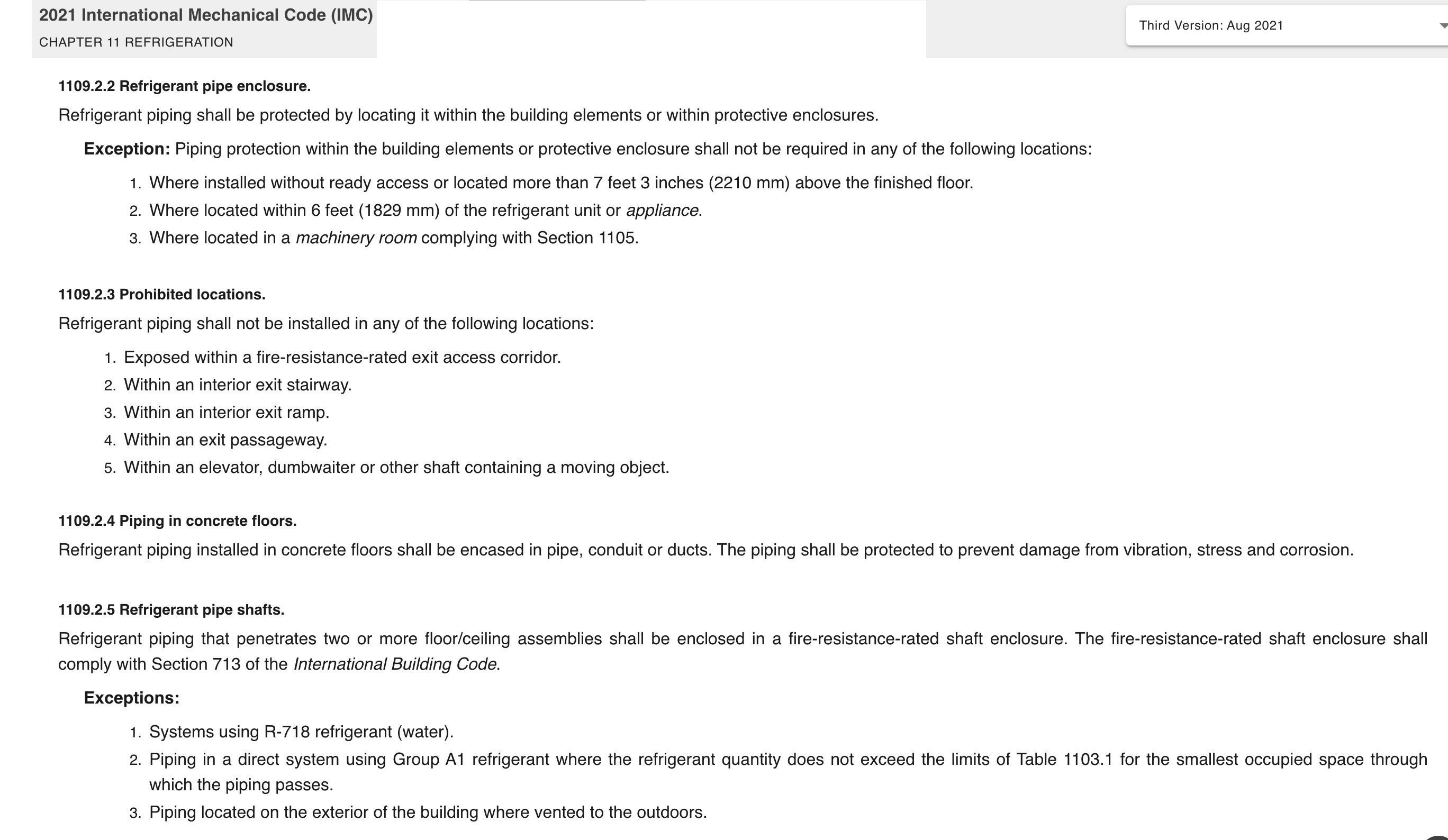
E.g. in the 2021 IMC (and prior versions a well), see this section of
IMC Chapter 11 REFRIGERATION
[in the IMC International Mechanical Code]
1101.3 Protection [of refrigerant tubing or piping]
This excerpt is as adopted by New York City - original source: https://codelibrary.amlegal.com/codes/newyorkcity/latest/NYCadmin/0-0-0-95450 )
Any portion of a refrigeration system that is subject to physical damage shall be protected in an approved manner.
Details of refrigerant piping protection are in the IMC in 1109.2 PIPING PROTECTION
And importantly, also in section 1109.3, for example
IMC 1109.3.1 [Refrigerant ] Pipe Protection
In addition to the requirements of Section 305.5, aluminum, copper and steel tube used for Group A2L and B2L refrigerants and located where tubing is installed in stus, joists, rafters, or similar spaces, and located less than 1 1/2 inches (38mm) from the nearest edge of the member, shall be continuously protected by shield plates.
Protective shield plates having a minimum thickness of 0.0575 inch (1.46 mm) (No. 16 gage) shall cover the area of the tube plus the area extending not less than 2 inches (51 mm) beyond both sides of the tube.
And finally
IMC 1109.6 [Refrigerant piping] Stress and strain
Refrigerant piping shall be installed so as to prevent strains and stresses that exceed the structural strength of the pipe. Where necessary, provisions shall be made to protect piping from damage resulting from vibration, expansion, contraction and structural settlement.
Similarly, HVAC system condensate piping must also be protected from damage due to condensation
see
IMC 1109.7 Condensate Control
Refrigerant piping and fittings that, during normal operation, will reach a surface temperature below the dew point of the surrounding air, and are located in spaces or aras where condensation has the potential to cause a safety hazard to the building occupants, struture, electrical equipment or any other equpment or appliances, shall be insulated or protected in an approved manner to prevent damage from condensation.
You can see that this code text anticipates that piping is routed through joists, rafters, or studs and the code writers, understanding that the choice of routing path itself is part of the piping’s protection, assumed (a mistake IMO) that the installer wouldn’t be foolish enough to install piping snug against or even within 1 1/2” from the the roof deck or any other surface through which it would be reasonable to expect that fasteners might be driven.
A classic example of refrigerant line protection discussed above on this page is the use of nail plates where refrigerant pipes are routed through studs.
Since building codes require (and as you are a roofer you know this) shingle fastener nails are expected to penetrate through typical residential roof decking by no less than the pointed end of the nail and may extend considerably further. So running a refrigerant line up against the underside of roof decking absolutely invites refrigerant line penetration.
However I am puzzled about why repairing a perforated refrigerant line and re-charging the system would cost $2,500. That sounds remarkable, unless some other work was done at the same time. I'd like to see details of what work was performed.
It would be helpful if you could send me photos of the area where the piping is routed, showing it against the roof deck, and photos of the damage.
Above on this page we discuss the requirement to protect refrigeration piping from damage. See details
at REFRIGERANT LINE NAIL PROTECTION
[Click to enlarge any image]
Inspect the Underside of the Roof before Bidding on a Roof Job
Watch out: OPINION: roofers bidding on a roof installation or re-roof job would benefit from an inspection of the roof from the attic side, noting the condition of roof decking and framing and also noticing if there are mechanical or electrical systems installed too close to the roof decking underside.
The Asphalt Shingle Fastener illustration below shows proper nail length for roof deck penetration, showing that there should be a minimum of 1/4" penetration of the shingle nail beyond the underside of the roof deck. Nails can be longer and protrude further, but they can't be shorter when using common 1/2" nominal thickness plywood roof decking.
[Click to enlarge any image]
Below our photo shows roof decking condensation, mold, possibly some plywood roof deck delamination, and as we discuss here, the normal and proper practice of seeing that the tips of the shingle nails penetrate through the roof decking.
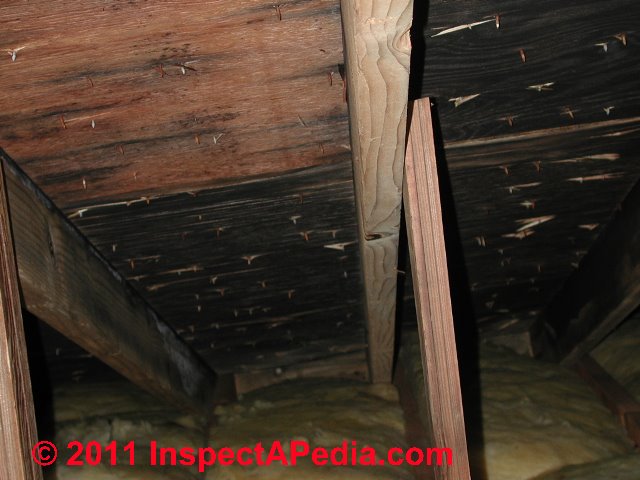
That step an avoid surprises like roofing nail-punctured or screw- or staple-punctured electrical wires or refrigerant piping as well as the occasional step through rotted roof decking.
On 2022-08-24 by Anonymous by private email - AC refrigerant line installation error: tight against roof decking - led to leak & expensive repairs
We recently replaced a roof on a house with a 2 year old retrofit AC system that had been added. The AC lines were against the bottom side of the plywood where entering the house from outside without any metallic barrier or cover. A roofing nail penetrated the line and cost our company $2500 in repairs and recharging.
The AC contractor claims that it is standard of practice to run AC refrigerant lines without shielding against the underside of roofing plywood.
Your view? Anything in the codes about this? - Anonymous by private email 2022/08/24
On 2022-08-21 by InspectApedia-911 (mod)
@Vahid,
Definition of "Refrigerant piping"
I take to refer to the piping that contains refrigerant (high-side and low-side lines), along with controls (TEV, cap-tubes, etc). Some may include condensate drain piping in the topic.
Definition of "Refrigerant pipework"
is a bit of a vague term that could refer to the labor involved in installing or maintaining or repairing refrigerant piping (refrigerant high and low pressure lines and possibly including condensate drain piping).
On 2022-08-21 by Vahid
Discuss what you consider to be refrigerant pipework?
On 2022-08-13 by InspectApedia-911 (mod)
@Jr,
Thanks for the comment but help us make it useful to other readers if you can: to what question, comment, or situation were you adding your comment. Surely not Michelle's worry about water vapor, unknown substances, and cellulose insulation in her home.
On 2022-08-13 by Jr
That probably happend because fuse box or electrical box wasnt ground it . Probably some one worked on it than a power cable touch the box sending voltage to the aluminum cover than refrigerant lines were grounded causing a spark upon contact
On 2022-08-08 by InspectApedia-911 (mod)
@Michelle Castile,
Try using the Add Image button to post your image file.
About the water vapor + cellulose insulation + soil filtration lines + sediment - and staining throughout your home, I can't offer an explanation of how that might be connected to a refrigerant leak though inadequate dehumidification could be a factor.
You need an on-site expert to review your observations and to make their own thorough diagnostic inspection.
Do keep us posted as what you find may help others.
On 2022-08-08 by Michelle Castile
I've emailed you some time ago regarding a very unique and rare occurrence in my home. This consists of a water vapor of some sorts which has completely overtaken my entire home. It carries with it an unknown substance, although my state health department has confirmed there to be cellulose insulation part of it.
After this insulation was installed which is plugging up the soffits for air flow, Mt entire house changed dynamics. Carpeting became full of a sediment which is what is in this water vapor. Upon my AC unit being replaced recently, I have some concerns as I'm seeing a lot of the same material which is in my carpeting, furniture, bedding, ect. I have what looks like soil filtration lines, yet these lines are jam packed with this sediment.
Building scientists cannot figure this out. These lines where the majority of this settles, although it is absolutely everywhere, even underneath furniture which sits on the floor, has an oily feel to it. Our AC unit had to be replaced due to a refrigerant leak as you will see just how corroded this A coil is that was removed. Possible similarities here??
On 2022-07-01 by InspectApedia-911 (mod)
@Joe,
Where refrigerant piping is not at least 1 1/2" from the roof deck, you'd need to protect the lines from puncture or reroute them.
On 2022-06-30 by Joe - What is the code for hvac lines up against roof sheathing? Nail plates?
What is the code for hvac lines up against roof sheathing? Nail plates?
On 2021-05-24 by (mod) - routing refrigerant piping under the roof decking
@John,
Thank you that's a helpful question.
I don't think you will find an explicit statement in the model building codes about the distance below roof deck that's acceptable for routing air conditioning or heat pump refrigerant lines.
But there is a more-general requirement that does apply:
IMC 1109.3.1 Pipe Protection
In addition to the requirements of Section 305.5, aluminum, copper and steel tube used for Group A2L and B2L refrigerants and located where tubing is installed in stus, joists, rafters, or similar spaces, and located less than 1 1/2 inches (38mm) from the nearest edge of the member, shall be continuously protected by shield plates.
Protective shield plates having a minimum thickness of 0.0575 inch (1.46 mm) (No. 16 gage) shall cover the area of the tube plus the area extending not less than 2 inches (51 mm) beyond both sides of the tube.
In sum, refrigerant piping lines do need to be routed in a way that they're not exposed to damage OR they need to be protected from damage by steel protective plates. .
Because it's common for roofing nails to penetrate the roof deck it would make sense that the refrigerant lines would be several inches away from the deck. That's the same reasoning as applies to routing electrical wires that might be sent through rafters
On 2021-05-21 by John
Is there a code that states a minimum distance below a roof deck for refrigerant lines to be installed?
On 2019-12-16 - by (mod) -
Thank you Rohit; we're very grateful when you find our information accurate, useful, un-biased. We also welcome criticism, content suggestions, questions.On 2019-12-16 by Rohit Patel
Good article for Air Conditioner Refrigerant Line Installation Requirements & Refrigerant Line Defects.
On 2019-07-29 - by (mod) -
George:Let's be sure we know just what valve and what liquid is being discharged.
In NO case should refrigerant, in liquid or gas form, be discharged from your Trane (or any other brand) air conditioner or heat pump. That's not a normal condition, most likely (where do you live?) violates building and safety codes, and contaminates the environment.
If the "liquid" is water - condensate produce by air moving over a cooling coil, the it may be normal and proper, provided that the condensate is being properly directed to an acceptable drain.
On 2019-07-29 by George
The refrigeration valve on my Trane condenser keeps releasing and a large amount of liquid is discharged. Is this normal?
On 2019-02-06 - by (mod) -
YossiWe do not ever use flare fittings on refrigerant piping as they're not likely to withstand the pressures involved on the high side.
I think you probabaly mean swaged connections: one end of the copper tubing is enlarged to permit joining two sections of copper piping.
The swage joint is then soldered or brazed. Some swaging tools are shown in my photo.
Swage joints are discussed
at REFRIGERANT PIPING INSTALLATION https://inspectapedia.com/aircond/Refrigerant_Piping.php
On 2018-08-26 by YossiD
A friend of mine is having some problems with a room sized split air conditioner in his home. The unit is about three years old.
A few months ago the unit stopped cooling and an air conditioning technician confirmed that the gas had leaked out. To inspect the lines some drywall had to be removed form a lowered ceiling, and upon inspection a cracked flare nut was found. The technician said that this is a not uncommon occurrence.
Have you ever come across cracked flare fittings in small air conditioners? It seems to me that it's just a case of poor quality fittings. What do you think?
Anyway, the damaged fitting was replaced and the unit again functioned properly.
now my friend is having more trouble with the same unit, and the technician says that now there is leaking in the copper tubing itself. This is also a new on one me. The tubing was professionally installed and there are few bends. Unfortunately the tubing is in the wall, and partly behind a tiled bathroom wall, so revealing all of it to find the point of failure will be serious undertaking.
My friend is thinking of rerouting for convenience though the result will not be as aesthetic and the rerouted tubing will inconveniently routed on the roof of his home, where the compressor is located. Do you have any experience with leaks in copper tubing except at bends or points of "trauma?" Is the kind of cheap Chinese Fe-Al contaminated Cu tubing mentioned in Robert W Porter's post prone to leaking?
Thanks for any insights.
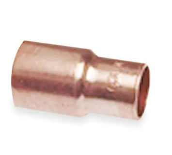
On 2020-07-14 - by (mod) - copper tubing diameter reducer
 JD
JD
Yes, you can buy a suitable copper tubing reducer, but depending on the difference in piping diameter the technician may simply use a swaging tool to join the copper tubing.
Above is an example, a Nibco copper reducer that converts from 1/2" to 1/4" copper.
On 2020-07-14 by Jd
If the connection on
New ac is bigger and and the lines coming out house is smaller can you get a converter and join both together?
On 2020-06-14 23:44:46.739185- by (mod) -
Tux
Yes it's possible to relocate a refrigeration compressor - commonly done with commercial systems and walk-in coolers. Not below a floor - it needs to be able to cool.
On 2020-06-11 by TuxIvy
BTW - the compressors fine...its location and hard floors multiply the effect (hums, fan noise, etc) of normal compressor operation.
We have an ice machine in the middle of the home that the compressor/fan is very loud. Its a great Hoshizaki residential under counter machine that gravity drains to the basement utility room below and never has issues.
With that said the fan/compressor noise forces us to turn it off for periods. Alternatively, is it a feasible idea to extend the compressor lines below the floor into the utility room? Moving the compressor to a room where the noise is isolated? I may want to use a flexible line so the machine can still be pulled out when needing to be serviced. Never needed to in 7 years but planning for the worst if possible.
Just checking if its feasible if I find a good AC or fridge guy to do it.
On 2020-05-07 - by (mod) -
Deb
If in the course of removing a freezer compressor motor or coils you break open the refrigerant piping, if there is refrigerant in the system you'll discharge it into the environment - a step that's illegal in many countries as it's a contaminant. If you keep them intact then you avoid that issue, but you may still need to contact your local environmental authority to ask how to dispose of that equipment.
The greater hazard is leaving doors on old refrigerators and freezers - a child hazard.
On 2020-05-07 by Deb
I have an old small deep freeze no longer any good I went to take the coils off back and the motor or whatever it is is it safe to unhook Arquette the copper tubing
On 2019-11-14 - by (mod) - increase in electric bill with new Rheem central air unit
Renee
I really do not know but that won't stop a guess: a wiring error including a short or current leak could be at fault here. You might get better diagnosis with an experienced electrician on site.
I like copper wire but PROPERLY MADE with pre-abrading through the antioxidant, use of antoxidant on the connectors, proper torquing of the connectors can give reasonable reliability on a single-use aluminum circuit such as to an A/C compressor/condenser unit.
On 2019-11-14 by Renée
I had a new rheem central heat & air unit installed 3 months ago, since then my electric bill has increased 113%.
The ac stopped cooling within the first 2 wks, said the breaker was tripped but took them 2 trips to figure it out. My heating stopped working 2 days ago, they said the breaker was tripped but there was also a hole in the cooper line.
Why does it keep tripping the breaker? I have read a lot of info online & it seems that I might be in for the long haul of future repair bills.
The copper pipes/tubing on the outside is are not insulated, I ask when they installed why it wasn’t, I was told it didn’t need to be. Is it suppose to be insulated? And I’ve read where using aluminum instead of cooper is better when it comes to leaks because the Formic acid won’t affect aluminum the same way it does copper, is it possible for the hvac guys to go back & change those?
I just paid several thousand for this unit & I can not afford future issues so I’m trying to find solutions now rather than later.
On 2019-07-15 - by (mod) -
Thickness, hardness, intended use.
I hsve not seen "type R" copper piping per se, but type "ACR" is specifically intended for use in refrigeration, air conditioning, heat pump systems.
See also
https://inspectapedia.com/plumbing/Copper_Pipes.php#CPTypes
On 2019-07-15 by Howard
Need to buy flexible 3/4" copper tubing for AC install. What's the difference between L and R tubing?
On 2019-04-14 0- by (mod) -
Barbara
Well I hate to get in the middle of dispute like this because I know someone's going to be mad.
But I have to say that people installing refrigerant piping should be perfectly aware of where it's vulnerable and should take steps to protect it.
Claiming that an older house doesn't have ro comply with code is a poor excuse in my opinion.
And in most jurisdictions, new work is required to comply with current codes.
But putting all of that code arm waving aside, aside if you know or can see with comparative you that there is a problem in your piping installation then you should sddress it at installation. Thats always going to be less expensive and we're satisfying to everyone then waiting for the problem to occur.
Good installation practice would require nail plates to protect piping where it passes through framing Lumber close enough that it could be punctured by a nail.
On 2019-04-13 by Barbara
We had a new A/C system installed in August. It worked great. We had new shingles installed on the roof in November. Now it is April. The system was turned on, but not cooling. Called HVAC company and was told there is a hole in the copper tubing near the soffit.
Said the roofer was at fault. Roofer said HVAC was at fault by not protecting the pipe when within 1-1/2 inches of possible nail. HVAC said code is for new homes, not ours built in 1986.
Who is correct? It cost us $800! HVAC has picture of tubing before removed. I’ve asked several times for it. I took picture of removed pipe. They found 2 holes.
IMAGE LOST by older version of Clark Van Oyen’s useful Comments code - now fixed. Please re-post the image if you can. Sorry. Mod.
On 2018-08-28 - by (mod) -
Refrigerant piping should be protected from physical or mechanical damage by either routing or shielding. For example where a line runs through a wooden stud you'd use nail plates to keep someone from driving a nail through the line.
See REFRIGERANT PIPING INSTALLATION
On 2018-08-28 by Des de Souza
Route of the freon line from the ac unit to the air handler. This goes up the side of my house and under the roof line. The last time I had a new roof, the roofers punched a hole in the freon line. Is there a code on whether the line should be installed low enough to prevent this from happening?
...
Continue reading at REFRIGERANT PIPING INSULATION or select a topic from the closely-related articles below, or see the complete ARTICLE INDEX.
Or see REFRIGERANT PIPING INSTALLATION FAQs - questions and answers posted originally on this page
Or see these
Air Conditioning & Heat Pump Refrigerant Piping Articles
- REFRIGERANT DRIERS & FILTERS
- REFRIGERANT PIPING INSTALLATION
- REFRIGERANT PIPING DAMAGE & LEAKS
- REFRIGERANT PIPING GURGLING
- REFRIGERANT PIPING INSULATION
- REFRIGERANT LINE MOUNTING
- REFRIGERANT LINE NAIL PROTECTION
- REFRIGERANT PIPING LENGTH vs DIAMETER
- REFRIGERANT TUBING BRAZING & SOLDERING
- REFRIGERANT TUBING FLARE CONNECTIONS
- REFRIGERANT TUBING ECONOMIZER & HEATING TRICKS
- REFRIGERANT PIPING UNDERGROUND, BURIED
- REFRIGERANT PIPING CODES & STANDARDS
- REFRIGERANT PRESSURE DIAGNOSIS
Suggested citation for this web page
REFRIGERANT PIPING INSTALLATION at InspectApedia.com - online encyclopedia of building & environmental inspection, testing, diagnosis, repair, & problem prevention advice.
Or see this
INDEX to RELATED ARTICLES: ARTICLE INDEX to AIR CONDITIONING & HEAT PUMPS
Or use the SEARCH BOX found below to Ask a Question or Search InspectApedia
Ask a Question or Search InspectApedia
Try the search box just below, or if you prefer, post a question or comment in the Comments box below and we will respond promptly.
Search the InspectApedia website
Note: appearance of your Comment below may be delayed: if your comment contains an image, photograph, web link, or text that looks to the software as if it might be a web link, your posting will appear after it has been approved by a moderator. Apologies for the delay.
Only one image can be added per comment but you can post as many comments, and therefore images, as you like.
You will not receive a notification when a response to your question has been posted.
Please bookmark this page to make it easy for you to check back for our response.
Our Comment Box is provided by Countable Web Productions countable.ca
Citations & References
In addition to any citations in the article above, a full list is available on request.
- Thanks to reader Anon. for discussing the allowable distance between air conditioner compressor and a building or from the air handler - July 2010
- In addition to citations & references found in this article, see the research citations given at the end of the related articles found at our suggested
CONTINUE READING or RECOMMENDED ARTICLES.
- Carson, Dunlop & Associates Ltd., 120 Carlton Street Suite 407, Toronto ON M5A 4K2. Tel: (416) 964-9415 1-800-268-7070 Email: info@carsondunlop.com. Alan Carson is a past president of ASHI, the American Society of Home Inspectors.
Thanks to Alan Carson and Bob Dunlop, for permission for InspectAPedia to use text excerpts from The HOME REFERENCE BOOK - the Encyclopedia of Homes and to use illustrations from The ILLUSTRATED HOME .
Carson Dunlop Associates provides extensive home inspection education and report writing material. In gratitude we provide links to tsome Carson Dunlop Associates products and services.
 | HOME | ABOUT | ASK a QUESTION | CONTACT | CONTENT USE POLICY | DESCRIPTION | POLICIES | PRIVACY | |
| © 2024 - 1985 Publisher InspectApedia.com - Daniel Friedman | |||||||||