
InspectAPedia® FREE Encyclopedia of Building & Environmental Construction, Diagnosis, Maintenance & Repair |
Question? Just ask us! InspectAPedia
|
 Air Conditioning & Heat Pump System Controls & Switches
- POST a QUESTION or COMMENT about how to find, identify, & use or troubleshoot each control or switch found on air conditioners or heat pumps.
HVAC system controls & switches: this article explains where to find and how to use the switches and controls for air conditioning and heat pump systems.
We list and explain the function of each air conditioner or heat pump control or switch, including providing identification photographs and troubleshooting tips.
We answer these common HVAC questions & complaints: What is the function of each air conditioning control or air conditioning switch? What check first if your air conditioning won't start. Key switches and controls to check if your air conditioner or heat pump is not working.
HVAC control definitions & photos are organized by where they are found: indoors or outside of the building, and at the air handler/blower assembly or the outdoor compressor/condenser unit, or perhaps in other locations such as wall thermostats or electrical panel main switches.
InspectAPedia tolerates no conflicts of interest. We have no relationship with advertisers, products, or services discussed at this website.
Air Conditioning & Heat Pump CONTROLS & SWITCHES
 We include photographs to assist readers in
recognizing cooling system defects. Individual HVAC control articles at this website discuss certain of these controls in greater detail
We include photographs to assist readers in
recognizing cooling system defects. Individual HVAC control articles at this website discuss certain of these controls in greater detail
Here we list all of the controls and switches on a typical split system air conditioner with indoor and outdoor components include the items listed just below.
We explain these many electrical switches and controls that control an air conditioner or heat pump system. You'll need to check these first if your air conditioner won't start or won't keep running.
[Click to enlarge any image]
If the A/C system won't operate, before requesting a service call check that it is turned on at every control, switch, or circuit breaker, and that the thermostat is properly set.
Article Series Contents
- A/C - HEAT PUMP CONTROLS & SWITCHES
- OUTSIDE HVAC SWITCHES & CONTROLS
- INSIDE SWITCHES & CONTROLS
- AIR HANDLER UNIT SWITCHES
- BLOWER DOOR SAFETY SWITCH
- BACKUP HEAT CONTROLS
- CAPILLARY TUBES
- CIRCUIT BREAKER SIZE for A/C or HEAT PUMP
- CONDENSATE PAN OVERFLOW SWITCH
- DUCT SYSTEM SWITCHES
- DUCT SYSTEM FILTERS
- SPILL SWITCHES on AIR HANDLERS
- STARTER CAPACITORS
- THERMOSTATS & CONTROLS
- THERMOSTATIC EXPANSION VALVES
- MOTOR OVERLOAD/ OVERHEAT RESET SWITCH
- ZONE DAMPER CONTROLS
- OPERATING CONTROLS, A/C & HEAT PUMP
If the A/C or heat pump system will not run
check all of these control and safety switches listed here before calling your service technician. If someone or some condition has turned one of these switches off, resetting it may be all that's needed.
Not all of these switches will be present on every system; fuses may be used instead of circuit breakers; fuse pullouts may be used instead of a circuit breaker or fuse at some service switches.
Watch out: Safety warning: do not put your fingers or hands inside of a heating furnace or air conditioner blower or blower compartment without making certain that all electrical power to the unit has been shut off. If the blower starts turning you can lose a finger, and there are also electrical shock hazards in these areas.
Key Air Conditioner or Heat Pump Main Electrical Control Switches, Fuses, or Circuit Breakers
- Air handler circuit breaker:
in the electric panel there will be a switch controlling power to the air handler/blower circuit, perhaps two different circuits, one for the air handler unit, and a second for the compressor/condenser unit (the next item listed below) - also
see CIRCUIT BREAKER SIZE for A/C or HEAT PUMP - A/C or Heat Pump Compressor circuit breaker:
in the electric panel there will be a switch, circuit breaker or fuse controlling power to the outdoor compressor circuit.
See COMPRESSOR DISCONNECT SWITCH and also
see CIRCUIT BREAKER SIZE for A/C or HEAT PUMP - A/C indoor Air handler service switch:
usually indoors at or right on the indoor air handler/blower unit, this switch is normally always "on" except during equipment servicing.
See also A/C or HEAT ON-OFF SWITCH LOCATIONS - A/C outdoor compressor/condenser
HVAC UNIT SERVICE SWITCH typically on the unit or on a building wall surface close to it. This switch is normally always "on" except during equipment servicing.
Also see OUTSIDE SWITCHES, Fuses, Breakers - Air conditioner or heat pump thermostat:
one or more indoor wall mounted thermostats must be set properly to call for cooling (or heating). Split system air conditioners and heat pumps may use a remote control device to turn the equipment on or off and to set the desired temperature.
See THERMOSTATS. - Other electrical switches and controls
such as an air conditioner or heat pump pressure safety switch found on or near the compressor/condenser unit and in some window and through-wall units can also shut down an air conditioner or heat pump system, as we discuss below in this article. - Electrical panel circuit breakers or fuses will be provided separately to control the air handler (blower system) circuit and the compressor/condenser circuit. Of these the compressor is usually supplied by a 240V circuit and the air handler by a 120V circuit.
- Compressor safety shut off switch
outside at the compressor/condenser. The switch may be a circuit breaker, fuse, or a simple "pull-out" disconnect located close to the compressor. - Air handler service switch inside on or close to the air handler unit itself
- Air handler blower compartment safety switch:
a safety interlock that will turn off electricity to the air handler or blower unit if the blower compartment door is not securely shut. If your air conditioner blower will not start this switch and the blower compartment doors should be checked.
See BLOWER FAN OPERATION & TESTING - Air conditioner/heat pump contactor relay switch:
turns on high amp drawing equipment such as the compressor motor.
See CONTACTOR RELAY DIAGNOSIS & REPAIR - Air conditioner or heat pump pressure control & pressure safety switches:
turns off the system at excessive refrigerant pressure and in some systems at too-low pressure. Also used in automotive air conditioning.
See PRESSURE CONTROLS & SAFETY SWITCHES
List of Outside A/C or Heat Pump Service Switches, Fuses, Circuit Breakers
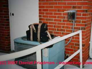
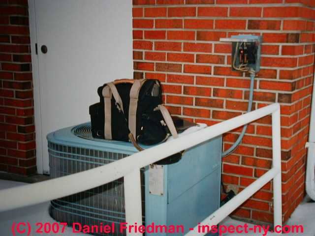
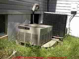
Just above are the outdoor air conditioner or heat pump compressor/condenser service control switch, in this case a circuit breaker, installed outside at a compressor
for a ductless cooling system compressor.
More photographs of a ductless or split system air conditioning system are
at A/C TYPES, ENERGY SOURCES.
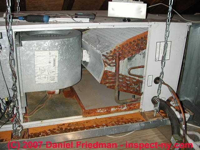
The air conditioning system compressor/condenser service switch shown at the top of this page, for an outdoor unit was a 240V fused circuit with 1/2" copper pipes in place of the original fuses.
This might be "safe" if the circuit were properly protected by breakers or fuses at the main panel, but the insertion of metal pipes
in these fuse sockets makes us suspect an unsafe condition:
someone wanted to force the compressor/condenser to run. The circuit fuses or breakers may not be working properly. This system could be dangerous.
Compressor Condenser Controls & Switches
 Circuit breaker(s) at the electrical panel
protect the circuit supplying power to the air conditioning system. Typically separate circuit breakers (or fuses) power the compressor/condenser unit and the indoor air handler/blower assembly.
Circuit breaker(s) at the electrical panel
protect the circuit supplying power to the air conditioning system. Typically separate circuit breakers (or fuses) power the compressor/condenser unit and the indoor air handler/blower assembly.
Watch out: your HVAC equipment may be run out of a sub-panel rather than the main electrical panel. Be sure you have found all of the electrical panels, sub panels, and manual control switches for the equipment both inside the building and outdoors.
Watch out: really watch out: if you re-set a circuit breaker or replace a fuse and the breaker trips again or the fuse blows again, leave the equipment off and call a qualified service technician. You probably have an unsafe condition. Forcing electrical equipment to run can cause shock or fire.
Compressor/Condenser Unit:
the "outside" portion of an air conditioner or heat pump, the compressor re-compresses refrigerant gas back into a liquid and in the process, moves heat (in the refrigerant) either from indoors to outside (air conditioning mode) or from outdoors to inside (heat pump mode) if the system is a heat pump.
See COMPRESSOR CONDENSER for details of the diagnosis and repair of compressor problems.
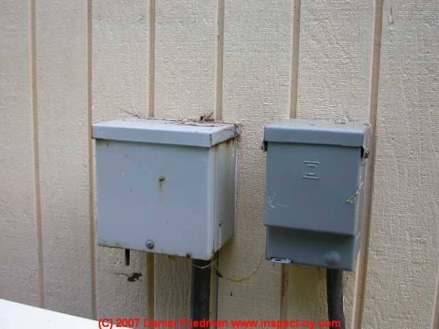
Compressor Service Switch or Disconnect Location & Distance
The air conditioning system compressor service switch is located outdoors, at the compressor/condenser unit, typically on a building wall near the outdoor unit, this switch may be a circuit breaker, a fuse block pull-out, or a simple electrical switch.
For details about this safety disconnect including where it is required, permitted distances, definitions of readily-accessible and visible, and pertinent electrical code citations and excerpts,
see COMPRESSOR DISCONNECT SWITCH.
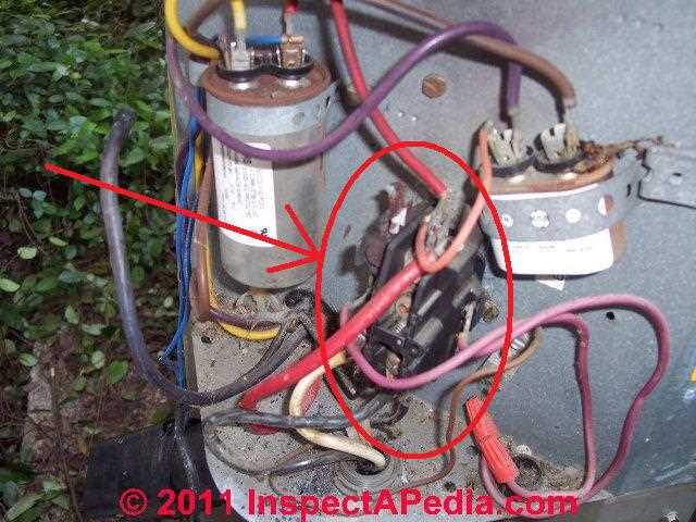
Air Conditioner/Heat Pump Contactor Relay Switch
A/C and heat pump systems use a contactor relay (circled at left) because the little 12-24V wall thermostat circuit and switches are not capable of handling the higher voltage used by the compressor/condenser motors.
The contactor relay is basically a low-voltage-operated switch [typically 12-14 volts] controlled by the low-voltage room thermostat) that switches a heavier-duty electrical relay to give 120V or 240V electrical power to the compressor/condenser unit.
Most A/C and heat pump contactor relays use an electromagnetic 24-volt two-pole contactor relay that is rated for 30 amps.
The "two poles" simply means that the relay switches two electrical wires simultaneously - which is what you'd expect if your heat pump motor is running on 240 Volts.
Tests for a Air Conditioner or Heat Pump Bad Contactor Relay: burned, buzzing, stuck open or closed
Check first by visual inspection for arc burn marks or badly burned, discolored, contactor points - replace a burned switch
DMM VOM Check: with power to the contactor switch/relay, that is with the points "closed" or touching, there should be zero resistance across the points.
Buzzing contactor relays: a buzzing contactor relay is failing; an emergency, short-term repair is to lubricate the switch (with an electrical contactor lubricant spray approved for that purpose), but the switch will need replacement.
Stuck contactor relay: a stuck contactor will be obvious: if the contactor never closes when energized it's stuck "open" and should be replaced. If a contactor relay stays closed even when power is removed, the switch is stuck "closed" and should be replaced.
Tips for changing out or installing a new magnetic contactor relay on an air conditioner or heat pump
Match the part numbers correctly when installing a new contactor relay in an air conditioner or heat pump. If the coil that activates the relay is not the right one for the compressor motor, you can have either of these problems:
Coil strength is too low: the coil won't reliably energize the start circuit in the motor and the compressor will be hard to get started
Coil strength is too high: the contactor relay coil won't let go of the start circuit: it will keep the start circuit active in the system even after the compressor motor has started - resulting in burning out the starter circuit.
Also locate a magnetic contactor relay switch in the proper physical position (mount it like the original was mounted) don't just hang the relay by its wires (as in our photo above). Some relays may be affected by gravity, either holding points closed too long or not holding the points closed. A current-operated contactor relay (most new units) can be mounted in any position.
Watch out: Some of our readers report successfully replacing minor electrical components such as switches, relays, and contactors. But unless you are qualified to do so we do not recommend trying to do work on electrical systems and components in your home as there are potentially fatal electrical shock hazards.
Because air conditioner compressor/condenser units include start/run capacitors even when you have turned off power you can get a nasty shock if you're not careful.
see CAPACITORS for HARD STARTING MOTORS
Also see SAFETY for ELECTRICAL INSPECTORS
Air Conditioner, Heat Pump, Refrigeration System Operating Pressure Control Switches & Electrical Sensor Safety Switches
We distinguish between operating control pressure switches and safety switches that monitor against too-low or too-high refrigerant pressures in a refrigeration system.
Both are described in detail at PRESSURE CONTROLS & SAFETY SWITCHES.
Excerpts are just below.
Operating Pressure Control Switches for Air Conditioners, Heat Pumps, Refrigeration Equipment
Operating pressure control switches set the normal compressor cut-in and cut out pressures in commercial refrigeration systems including air conditioners, coolers, refrigerators freezers.
Commercial refrigeration equipment such as refrigerators (coolers) and freezers use a pressure control switch to set the cut-in and cut out pressures at which the compressor shall operate.
The pressure control switch and the thermostatic expansion valve may both need to be inspected, tested, and set to cooperate with one another, as I describe in an old field service call report described
at REFRIGERANT METERING DEVICES TEVs & EEVs
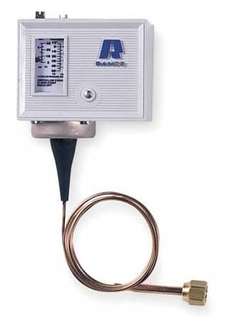
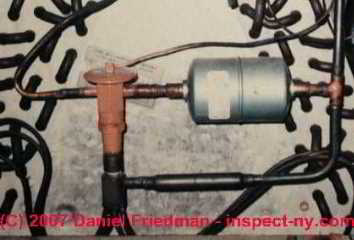
Shown above is a Ranco™ single pressure control switch with an operating range of 12-50 psig and a differential range of 5-35 psig. Ranco produces a wide range of switches and controls including air conditioning controllers. This particular Ranco switch shown at left "opens" on low.
Available from Grainger and other refrigeration equipment suppliers.
The Ranco Type "O" single function pressure controls are very widely used on refrigeration systems and can operate either as normal operating controls or as protection devices
See PRESSURE CONTROLS & SAFETY SWITCHES).
Refrigeration System Pressure Safety Switches: protect against over pressure or under pressure in air conditioning or heat pumps
Some HVAC systems (air conditioners, heat pumps, refrigeration equipment) include other sensor switches that may include an electrical pressure or temperature transducer/sensor (photo at left) or an air conditioning or heat pump pressure sensing switch that detects improper (too high) or [in some systems including automotive air conditioning] too-low refrigerant pressures in the system.
Details about these safety switches are
at PRESSURE CONTROLS & SAFETY SWITCHES. Excerpts are just below.
For safety the air conditioning or heat pump pressure switch can shut off the system. When pressures return to normal the pressure safety switch normally auto-resets and operation can continue.
Watch out: As Ranco and others warn, both under pressure (that can damage the compressor) and overpressure (that can damage or eve blow something up) at an air conditioner or heat pump system - can be dangerous need to be guarded against.
List of Inside Air Conditioner or Heat Pump Controls, Switches, Major Parts
Control Circuit Board - Air Conditioner / Heat Pump
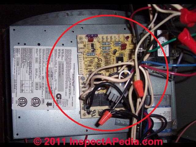
Control circuits (typically a "control board" shown in our photo at left) along with the contactor relay (discussed above) are used in the compressor/condenser to turn it off and on in response to the indoor thermostat's call for cooling.
While diagnosing a circuit or component problem within an air conditioner or heat pump control board is beyond the skill of most homeowners, a simple visual inspection might show you that the control board has been visibly burned, broken, or damaged. Of course the board may look OK and still be damaged.
See A/C - HEAT PUMP CONTROLS & SWITCHES for details.
Air Conditioner or Heat Pump Controls In or On the Air Handler Unit or Blower Compartment & At the Cooling Coil
Air Handler: the air conditioner or heat pump air handler is the "indoor" portion of the cooling (or heating) system whose job is to condition air from the living space by blowing air across a cooling coil (air conditioning) or heating coil (heat pump), sending the conditioned air on through supply ducts into the occupied space. The primary parts of the air handler unit include:
- Return air plenum:
return ducts from the occupied space bring building air to this collection point for passage into the air handler - Air filter:
may be located in or near the return air plenum or preferably, at return air registers. Additional air filtration equipment may be installed at the air handler on the return-air side, such as electrostatic air cleaners, UV light sterilizers, HEPA filters, or other air quality improvement devices.
See AIR FILTERS for HVAC SYSTEMS for details. Watch out: some HVAC systems may include a clogged or blocked air filter switch that you'll want to check.
This may be simply an indicator that pops out to indicate that the filter has become too dirty and is blocking air flow.
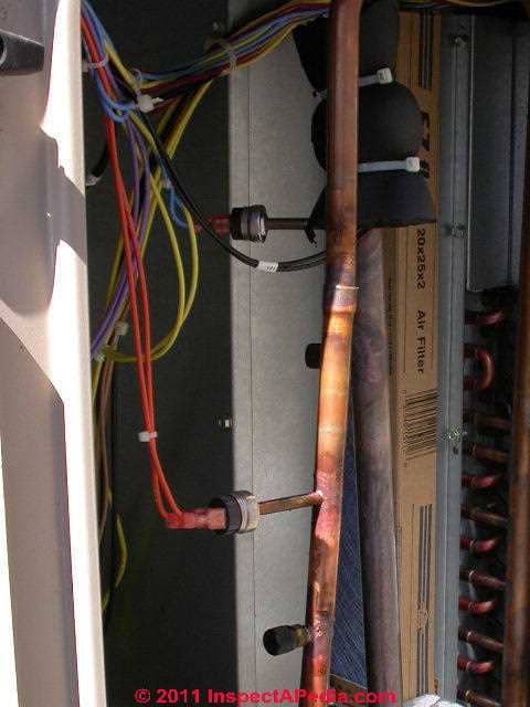
Thermostatic expansion valves & other refrigerant metering devices:
An air conditioner thermal expansion valve or "TEV" or just "expansion valve" (tan colored device in the photo) is a device located at the cooling coil and connected between the incoming refrigerant line and the refrigerant
inlet to the cooling coil in the air handler.
The thermostatic expansion valve is a refrigerant metering control device, and it is not a control or switch which can be directly operated when using an air conditioning system, but it is a critical control needed for metering refrigerant into the cooling coil, so we include its description here.
The TEV shown in this photo is used on a heat pump system so it includes extra tubing so that it can permit the refrigerant to reverse its flow of direction when changing from cooling mode (move indoor heat to outdoors) to heating mode (collect and move outdoor heat to indoors).
There is a variety of refrigerant metering devices and they're not all called "TEVs":
See THERMOSTATIC EXPANSION VALVES for details about the function, inspection, and installation of thermostatic expansion valves, automatic expansion valves,
CAPILLARY TUBES, manual and adjustable and non-adjustable expansion valves, high side and low side float valves, all of which are used to control refrigerant flow in refrigeration equipment such as heat pumps, air conditioners, refrigerators, freezers, and dehumidifiers.
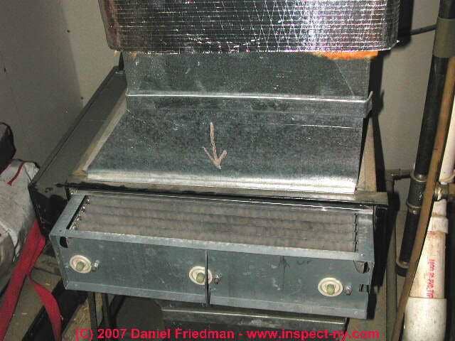
A/C or Heat Pump Air Handler Blower Door Safety Switch & Blower Compartment Switches
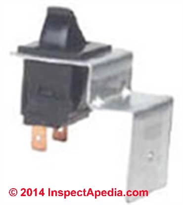
Blower compartment door switch: an air handler blower compartment access door switch is present on newer units, and can be seen as a button or switch which is depressed when the blower compartment door or cover is properly in place.
[Click to enlarge any image]
This switch shuts off the blower fan as a safety control if the door is opened.
If your air conditioner won't run and someone has been fooling with it, be double sure that the blower compartment door is properly closed and that the interlock switch sensor button or lever is properly depressed to convey that fact to the system.
Quoting Trane's typical equipment instructions:
The blower door safety switch will prevent or terminate furnace operation when the blower door is removed
Details about air handler, furnace, or air conditioner blower compartment door safety switch installation, testing, repair or replacement are
Other switches found inside the air handler unit
- Blower fan motor overload reset switch:
some air handler blower motors include a built-in thermal overload switch that will shut down the motor to protect it from damage. Some of these switches will automatically re-set themselves after the shut down motor has cooled. Other motors use a pop-up overload switch that must be manually reset.
See RESET BUTTON, ELECTRIC MOTOR - - Fan controls on thermostat:
see FAN AUTO ON THERMOSTAT SWITCH for details about what turns the blower fan on and off in normal use. - Blower motor overload or overheat switch:
a built-in overload protector used in some electric motors, especially the electric motor used to power the air handler's blower fan, may be tripped.
See BLOWER MOTOR SWITCH for details. - Spill Switches
on gas fired heating equipment: gas fired heating equipment may (and should) include a spill switch at the draft hood or burners to detect unsafe flue gas spillage.
An indoor air handler in heating mode may be shut down if the spill switch has detected unsafe conditions. Normally when in cooling mode the gas burners on a combined heating/cooling unit should be off and should not affect cooling.
See FLUE GAS SPILL SWITCH TRIPPING & RESET
Backup Heat Controls on Heat Pumps
- Heat Pump Heat & Backup Heat Controls:
if your cooling is provided by a heat pump system, during the heating season the same equipment is used to provide heating as was used to provide cooling during hot weather.
Heat pumps in climates where temperatures can get lower than the heat pump can handle include
a BACKUP HEAT SOURCE and all heat pumps include additional controls: an outdoor thermostat that monitors outside temperature and decides when to switch the backup heating system on; - a REVERSING VALVE on HEAT PUMPS that switches the direction of refrigerant
- an INDOOR THERMOSTAT which can be set to auto, heat, cool, or off modes.
- A/C or HEAT ON-OFF SWITCH LOCATIONS -
often a generic "HEAT ON/OFF" red switch plate might actually be controlling a heat pump or air conditioner, and conversely, sometimes the service switch or On-Off switch plate will not be red but silver metal or white or another color - Supply plenum:
a compartment which receives conditioned air from the cooling (or heating) coil and delivers this air to one or more ductwork systems which in turn move air to various areas of the occupied space.
See AIR HANDLER / BLOWER UNITS for details.
Condensate Overflow Pan Safety Switch
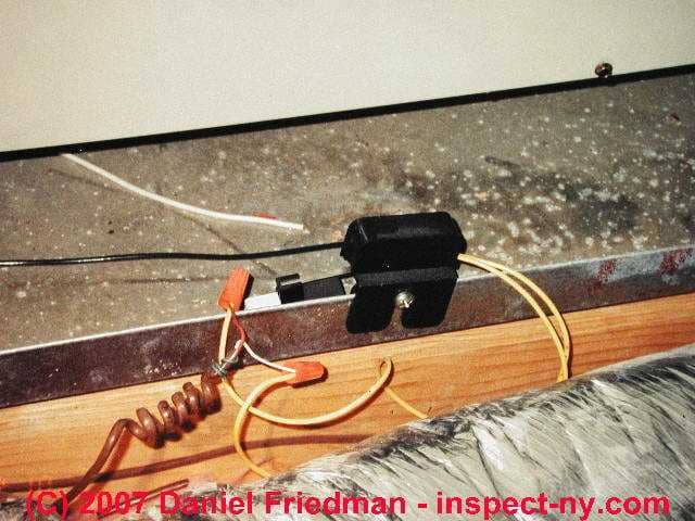
Condensate overflow tray sensor switch: at the air handler, especially in an attic or closet or upper floor air handler, installers may provide an electrical switch (rather than a separate drain pipe) to detect spillage of air conditioner condensate out of its normal air conditioning condensate drain pipe.
When we cool air inside the air handler, that step causes moisture in the air to condense out as a liquid condensate that must be collected and disposed-of.
The condensate overflow switch is a sensor which turns off the air conditioning system as soon as it detects water in the condensate drip tray - thus avoiding a costly leak into building ceilings or floors and perhaps avoiding a mold contamination problem.
See CONDENSATE PAN FLOAT SWITCH in our discussion of condensate drip tray defects
and CONDENSATE PAN SWITCH LOCKOUT in our discussion of reasons why an air conditioner or heat pump won't start
Thanks to Lester Richter for this tip.
Circuit breaker - compressor: in the building main electric panel there will be a switch controlling power to the compressor/condenser unit. Typically this is
a 240V circuit operated by a double pole circuit breaker or a fuse pair.
Circuit breaker - air handler/blower: in the electric panel there will be a circuit breaker or fuse controlling power to the air handler/fan unit which distributes cool air in the building. This will typically be a separate 120V circuit dedicated to protecting the circuit which supplies electric power to this equipment
Duct System Components, Controls, Switches
Duct System:
the air conditioning air ducts (or ductwork) (or heat pump duct work) carry conditioned air from the air handler to various rooms in the occupied spaces of the building.
Return air ducts
bring air from the occupied space to the air handler. In some installations only a single return air register and return air duct may be installed, usually in the ceiling over a stairwell in a two-story home; where multiple return ducts are provided you will find two or more return registers in the building;
If you observe that most rooms have only a supply register and duct and no individual return air ducts, keeping the room doors open will probably improve air circulation and reduce heating or cooling costs for the building.
Supply air ducts
bring air from the air handler (where it has been cooled and dehumidified, or heated if a heat pump is in heating mode) back into the occupied spaces in the building. Where each supply duct enters a room through the room ceiling, wall, or floor, a finned supply register should be installed to permit control of the direction and amount of air that exits the duct at that location.
Zone dampers:
HVAC ducts in some installations may include motorized zone dampers controlled by individual room thermostats or switches.
See ZONE DAMPER CONTROLS for details about these controls.
See DUCT SYSTEMS for details about inspecting, diagnosing, and correcting a broad range of HVAC air duct problems.
Duct System Filters on HVAC Systems
Filters: air filters provide one or more levels of air filtration should be found installed on any air conditioning or warm air heating system.
Our photo shows an electrostatic air cleaner installed on an air handler. This installation included a disposable air filter installed at a central return air inlet grille (not visible in this photo) so that the air cleaner itself needed cleaning less often.
Air filters may be installed at the return registers, at the air handler, or on occasion at other locations.
See AIR FILTERS for HVAC SYSTEMS.
Starter Capacitors and Start/Run Capacitors on HVAC System Motors
A bad starter capacitor or the need for one where none is installed can be the cause of motors that fail to start, motors that chatter or stutter, or electric motors that won't keep running (bad run capacitor).
See CAPACITORS for HARD STARTING MOTORS.
Thermostats & Controls on HVAC Systems

The photograph above shows a typical indoor thermostat used to control heating or cooling. Note that in this photo the thermostat is switched to "heat" mode. The air conditioner will not run with the switch set to "heating".
Thermostats for air conditioning systems or heat pumps:
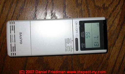
The photo just above shows a remote control thermostat used indoors to control the indoor wall-mounted cooling unit of a ductless cooling system.
An air conditioning system thermostat is a switch to turn on or off the A/C equipment as indoor air temperature varies around the thermostat's set point.
See THERMOSTATS for details of the operation of air conditioning, heat pump, and heating system thermostats and switches.
More photographs of a ductless air conditioning system are
Thermostatic Expansion Valves at A/C or Heat Pump Coils
Another type of thermostat that controls heating and cooling in your HVAC or heat pump system is the TEV or thermostatic expansion valve. This device monitors temperatures at the evaporator coil in the air handler and meters refrigerant into the coil accordingly. TEV devices can fail in several ways, Often involving a clogged sensor tube.
While it's possible to fool around with some TEV's, tap on them, adjust their metering rate, etc. this task should be left to your service technician since without proper training and test equipment you will have little idea where the adjustment has been set (if it can be set).
Thermostatic expansion valve:An air conditioner thermal expansion valve or "TEV" or just "expansion valve" (tan colored device in the photo) is a device located at the cooling coil and connected between the incoming refrigerant line and the refrigerant inlet to the cooling coil in the air handler.
The thermostatic expansion valve is a refrigerant metering control device, and it is not a control or switch which can be directly operated when using an air conditioning system, but it is a critical control needed for metering refrigerant into the cooling coil, so we include its description here.
The TEV shown in this photo is used on a heat pump system so it includes extra tubing so that it can permit the refrigerant to reverse its flow of direction when changing from cooling mode (move indoor heat to outdoors) to heating mode (collect and move outdoor heat to indoors).
See THERMOSTATIC EXPANSION VALVES for details about the function, inspection, and installation of thermostatic expansion valves.
Motors in HVAC Systems: Electric Motor Overload or Overheat Reset Switches
There are at least three electric motors in a conventional air conditioning or heat pump system, plus sometimes a fourth:
- An indoor blower fan motor -
causing air to move across the evaporator (cooling) coil [or heating coil in heat pump mode], and through the duct work into occupied spaces. - An outdoor compressor motor -
compressing refrigerant gas back into a liquid - An outdoor compressor unit fan motor -
draws air across the condensing coils to condense hot refrigerant gas back to liquid form. - Condensate pump motor
some systems also use a condensate pump or condensate drain pump to help remove condensate from the air handler to a building drain.
A failure here that leads to lost cooling can be subtle: if the condensate removal system fails (bad pump, clogged drain) and if condensate spills into an overflow pan that uses a sensor switch to detect this condition, the failed condensate motor can actually stop an air conditioner from running.
Any of these motors can fail to start or may be "off on reset" due to a motor overload, or motor overheating.
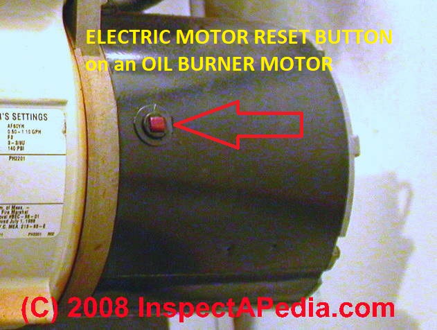
Air conditioner fan or blower motor overload reset buttons:
An air conditioner fan or blower motor overload reset button may be present on the blower motor in the air handler/blower compartment.
Look for a red or yellow button which is normally flat with the motor surface but which will pop up to show that the motor has been shut off by its internal overload protection circuit.
Some electric motors (such as submersible well pumps and some A/C or heat pump compressors) have an internal thermal reset switch that will reset automatically when the motor cools down. Others such as that shown in our photograph have to be reset manually by pushing the button in when the motor has cooled.
See ELECTRIC MOTOR OVERLOAD RESET SWITCH for details of how to find and how to reset this switch when necessary.
Zone Dampers & Zone Controls on Heating and Air Conditioning Systems
Some heating and air conditioning systems use manual or automatic zone dampers to control the flow of conditioned air to different building areas. A manual damper is just a lever somewhere in the duct work that opens or closes a baffle inside the duct to limit air flow through that duct section.
An automatic zone damper may be controlled by an individual thermostat for the area served by that zone. So if the heating or cooling system is not running, or if it is running but not sending air to an area in the building, look for and check out any manual and automatic zone damper controls.
Details about zone dampers used on ductwork: warm air zones and air conditioning zones and zone dampers are
If the A/C system will not run
check all of these control and safety switches before calling your service technician. If someone has
turned one of these switches off, resetting it may be all that's needed. Not all of these switches will be present on every system; fuses may be used instead of circuit breakers; fuse pullouts
may be used instead of a circuit breaker or fuse at some service switches.
Watch out: Safety warning:
do not put your fingers or hands inside of a heating furnace or air conditioner blower or blower compartment without
making certain that all electrical power to the unit has been shut off. If the blower starts turning you can lose a finger, and there are also
electrical shock hazards in these areas.
How to diagnose and fix an air conditioning system that is not working
Since the failure of an air conditioner to turn on, loss of air conditioner cooling capacity, reduced air conditioning output temperatures, loss of cool air supply, or even loss of air flow entirely can be due to a variety of problems with one or more components of an air conditioner or air conditioning system, after reviewing the lost air conditioner cooling diagnosis procedures described in this article, be sure to also review the diagnostic procedures at each of the individual air conditioning diagnosis and repair major topics listed just below.
To return to our air conditioning and refrigeration home page go
to AIR CONDITIONING & HEAT PUMP SYSTEMS.
If your air conditioning or heat pump system has lost its cooling capacity or won't start select one or more of the diagnostic articles listed below.
- A/C REFRIGERANT LEAK DETECTION: how to use a TIF5000 to detect air conditioning refrigerant gas leak
- A/C DIAGNOSTIC FAQs: air conditioning system diagnostic FAQs: Q&A about air conditioner repair - a detailed air conditioning system diagnostic checklist
- AIR HANDLER UNIT: problems with the air handler, air filters, and the cooling coil itself
- BLOWER DOOR SAFETY SWITCH - interlock shuts off the indoor air handler if a blower door is open
- CONTROLS & SWITCHES: air conditioner controls and switches - begin here if your A/C won't start. Here's an important tip: most refrigeration problems, in air conditioners, refrigerators, or freezers, are electrical, not mechanical. In air conditioning school, we used to drive out and collect abandoned refrigerators that people were tossing out during our community's spring cleanup week.
Taking these appliances back into the shop we found that almost always the problem that had caused the owner to dispose of their air conditioner or freezer was in an electrical connection or electrical control. So it's worth checking out switches and controls on an air conditioner before replacing more costly components. - COMPRESSOR CONDENSER: problems with air conditioner compressor/condenser units
- COMPRESSOR DISCONNECT SWITCH - blown fuse or power switched off
- DUCT SYSTEM DEFECTS: problems with the air duct system, air filters, supply registers, return air registers
- LOST COOLING CAPACITY: what to do when not enough cool air comes out of the system
- WHAT TO CHECK FIRST if there is no cool air or not enough cool air
- COMPRESSORE FAILURE DIAGNOSIS: basic checks of the air conditioner compressor
- DUCTS & AIR HANDLER DIAGNOSIS: basic checks of the indoor air handler (blower), air ducts, and filter systems
- OPERATING DEFECTS: major air conditioning problem symptoms and how to get the air conditioning system working again,e.g. compressor or fan noises, failure to start, and inadequate cool air volume
- OPERATING CONTROLS, A/C & HEAT PUMP for a discussion of thermostats, zone dampers, and circuit breakers on air conditioners and heat pumps.
- THERMOSTATS and THERMOSTATIC EXPANSION VALVES.
Reader Comments, Questions & Answers About The Article Above
Below you will find questions and answers previously posted on this page at its page bottom reader comment box.
Reader Q&A - also see RECOMMENDED ARTICLES & FAQs
On 2024-01-28 by InspectApedia Publisher - chattering relay and air conditioning or heat pump start up problems.
@Rich,
That's good news, and thank you for taking time to provide feedback as that will help other readers also facing chattering relay and air conditioning or heat pump start up problems.
I wouldn't assume however that a future repair isn't going to be needed. I have found often with mechanical equipment that a marginal control or relay or device can be got going again but when we leave the equipment off for a time we are back where we started.
On 2024-01-28 by Rich
@InspectApedia Publisher, Just wanted to report back that everything is still running good with no chatter in the air handler. The system has probably cycled on and off, in regular heat mode, about 25 times now and, thankfully, no more noise.
On 2024-01-26 by InspectApedia Publisher
@Rich,
Yes that's certainly possible.
On 2024-01-26 by Rich - Could it be that the reversing valve was stuck
@InspectApedia Publisher, Okay, so last night I set my thermostat to the A/C mode and powered it on, essentially moving the reversing valve inside of the condenser. I ran that for a few minutes then shut it down. After that, I switched the thermostat back to heat mode and turned it on and there was no clicking noise at all coming from the air handler.
Could it be that the reversing valve was stuck, possibly? I'm keeping my eye on it because I'm not convinced that this was the actual fix but hoping that maybe that was the problem.
On 2024-01-26 by InspectApedia Publisher
@Rich,
We're glad to help and look forward to hearing what you find.
On 2024-01-26 by Rich
@InspectApedia Publisher, Okay, yes... That's what I was wanting to know. This past summer, I replaced the contactor on my outside condenser, along with the capacitor and relay switch.
I didn't realize that there is contactor(s) on the inside air handler unit. I will take a look at the schematic on the inside panel as you had suggested and try to narrow down the problem. Hopefully get a part number and place an order.
I will let you know how I make out.
Thanks again for the information. You have been extremely helpful.
On 2024-01-26 by InspectApedia Publisher - several relays, also called "contactors" - identified on the wiring diagrams
@Rich,
There will be several relays, also called "contactors" - identified on the wiring diagrams for the indoor air handler and the outdoor compressor condenser unit.
One may, for example, turn on the compressor motor, another the fan.
On 2024-01-25 by Rich
@InspectApedia Publisher, Yes, the outside compressor condenser does start to run but whatever is inside the air handler that sends the signal for the outside compressor condenser to turn on is clicking on and off rapidly.
The lights in my basement even flicker when this is happening so I don't allow it to run like that for more than a few seconds because I don't want to damage anything.
What is the electrical part that controls the outside compressor condenser on these older systems? Again, no circuit boards in the electrical area above the blower. Thanks so much for your insight.
I really appreciate it as I can't find anything else online regarding this issue.
Sorry, I know you said the relay is what controls the outside unit to turn on. I was just wondering if there is a specific name for it. Thank you.
On 2024-01-25 by InspectApedia Publisher - there is a constant clicking noise from the inside air handler
@Rich,
That clicking sounds to me as if a relay in your air handler is not working.
A question is does the outdoor compressor condenser unit start to run when you call for heat?
There's also a reversing valve that switches the direction of flow of refrigerant in the system that could be sticking but I would expect that you would hear that and the outdoor unit not the indoor unit.
Look inside the air handler and on the back of the door covering the blower compartment to see if you can find a wiring diagram and you should be able to identify any relays and from that you may be able to track down which one is either not pulling in or is pulling in but whatever is trying to start, such as the compressor condenser unit, isn't starting.
On 2024-01-25 by Rich
I have an old RUUD heat pump/central A/C manufactured in 86', so there are no circuit boards in the electronics area of the air handler. I recently replaced the blower motor and capacitor, as well as thoroughly cleaning everything.
When I run the system in just fan mode (no heat) it runs perfect. When I run the system in "emergency heat" it runs perfectly. But when I run the system in regular heat mode, there is a clicking noise I hear from inside of the electrical are of the air handler.
So every time it calls for heat from the outside condenser, there is a constant clicking noise from the inside air handler. Could this be some sort of relay switch or something?
On 2023-06-19 by InspectApedia Publisher - How do I turn A/C back on?
@Anonymous,
Wait 45 minutes, then simply turn the power switch back on and it should work normally
Some A/C compressor/condenser units won't run immediately after turning power off because the compressor can't start against high head pressure that develops during normal operation
A pressure sensor may be present that prevents restart at high refrigerant pressures.
By waiting a bit, refrigerant pressures in the system will equalize and fall to a much lower pressure.
Then the compressor will restart.
Let me know if that works for you..
On 2023-06-18 by Anonymous
Accidently touched a switch that I thought was hallway switch and instantly shut off A/C. How do I turn A/C back on?
On 2023-01-12 by InspectApedia Publisher - thermostats wouldn't turn on the heat
@Bob Howell,
Gee I'm surprised. The thermostat is in essence just an "on-off" switch that connects the two T T wires together at the thermostat on a call for heat.
PROVIDED that we're talking about a standard 24VAC thermostat circuit (that is, not electric heat or some other system that has to switch a 120VAC or 240VAC relay),
I'd do this test:
Remove the thermostat from the wall and try just jumping the two wires together (red and white usually).
If the heat starts then we know the TT wires and connections at the other end are correct and we can go back to investigating the thermostat itself and its settings.
On 2023-01-12 by Bob Howell
I have tried 3 smart thermostats. Each one correctly installed and wired. The thermostats worked well except none would turn on the heat. I live in an apartment. It is heated and cooled with a heatpump.
I suspect that the original installed thermostat, a manual Braeburn 2020NC is the only one which can be installed to run this heat pump.. Could I be correct in this assumption?
On 2021-07-30 by inspectapedia.com.moderator
@lorenzo,
Are you asking if the coils were in series or parallel ?
On 2021-07-30 by lorenzo
morning am trying to solve a situation a former refrigeration left . am working on a continental drop in pizza fridge. it carries two evaporator coils ,one compressor,one condenser. the serial umber is not visible. the expansion valve has been cut out along with some tubing. am trying to figure out if this system was in series or parallel. modul #cpa118
. thank you
email ; lbutler422@icloud.com.
On 2021-07-16 by inspectapedia.com.moderator - should I be running my air conditioner in "exhaust" or in "fresh air" mode
@Anonymous,
There is no "right or wrong" answer that fits all cases of the question of "should I be running my air conditioner in "exhaust" or in "fresh air" mode.
Use exhaust to reduce indoor odors
Use fresh air to improve indoor air quality and to dilute indoor air that has odors.
On 2021-07-16 by Anonymous
Air control , fresh or exhotst
On 2021-05-12 by danjoefriedman (mod)
@Roy,
It is distressing to keep replacing the motor without finding out the underlying cause that seems to be killing them. There could be a different problem such as low voltage to the compressor motor or a miscalculation of the refrigerant charge causing liquid refrigerant to damage the compressor motor.
Or of course it's something else. So if you have to replace this motor to I would talk to the service manager at your HV AC Service Company and ask him to send out an experienced diagnostician to see if there's an underlying problem that should be corrected.
On 2021-05-08 by Roy
Condenser motor runs half speed then tripped mind u this is a new motor had 2
...
Continue reading at CAPILLARY TUBES or select a topic from the closely-related articles below, or see the complete ARTICLE INDEX.
A/C HEAT PUMP CONTROL / SWITCH FAQs - questions & answers posted originally at this article
Or see these
Recommended Articles
- A/C & HEAT PUMP OPERATING CONTROLS - thermostats, zone dampers, and circuit breakers on air conditioners and heat pump systems.
- AIR CONDITIONING & HEAT PUMP CONTROLS & SWITCHES - full set of all controls
- COOLING & HEATING CONTROL & SWITCH INDEX
- ELECTRICAL POWER SWITCH FOR HEAT
- FURNACE CONTROLS & SWITCHES
- MANUALS & PARTS GUIDES - HVAC - home - Master Index to All Brand Names & HVAC manuals, wiring diagrams, installation and repair guides
Suggested citation for this web page
CONTROLS & SWITCHES, A/C - HEAT PUMP at InspectApedia.com - online encyclopedia of building & environmental inspection, testing, diagnosis, repair, & problem prevention advice.
Or see this
INDEX to RELATED ARTICLES: ARTICLE INDEX to AIR CONDITIONING & HEAT PUMPS
Or use the SEARCH BOX found below to Ask a Question or Search InspectApedia
Ask a Question or Search InspectApedia
Try the search box just below, or if you prefer, post a question or comment in the Comments box below and we will respond promptly.
Search the InspectApedia website
Note: appearance of your Comment below may be delayed: if your comment contains an image, photograph, web link, or text that looks to the software as if it might be a web link, your posting will appear after it has been approved by a moderator. Apologies for the delay.
Only one image can be added per comment but you can post as many comments, and therefore images, as you like.
You will not receive a notification when a response to your question has been posted.
Please bookmark this page to make it easy for you to check back for our response.
Our Comment Box is provided by Countable Web Productions countable.ca
Citations & References
In addition to any citations in the article above, a full list is available on request.
- Trane Corporation, "TUX-D-2 Upflow/Horizontal Left Downflow/Horizontal Right Condensing Direct Vent Gas Fired Furnace XR90 TUX040-series, single-stage fan assisted combustion system" from Trane, retrieved 11/5/2014, original source: http://www.trane.com/commercial/uploads/pdf/1112/tux_c.pdf
- Thanks to Alan Carson and Bob Dunlop, Carson Dunlop, Associates, Toronto, for permission to use illustrations from their publication, The Illustrated Home which illustrates construction details and building components. Carson Dunlop provides home inspection education, publications, report writing materials, and home inspection services. Alan Carson is a past president of ASHI, the American Society of Home Inspectors.
- Thanks to Lester Richer, a professional home inspector, for the reminder that a bad air conditioner condensate drip tray switch can shut the whole system down.
- Behr Hella Service A/C pressure switches,
- Grainger, http://www.grainger.com/
- Ranco Corporation, http://www.invensyscontrolseurope.com/ranco/ Tel (Europe) +44 (0)845 130 5522
- Sensata Technologies, 529 Pleasant Street, B41 Attleboro, MA 02703-2964 Phone: 1-248-692-5600 Fax: 1-248-692-5630 Email: auto-mktg@sensata.com Web: www.sensata.com, pressure switches for automotive air conditioning systems
- Micro Pneumatic Logic, Inc., Pompano Beach, Florida Tel. (954) 973-6166 - pressure switches
- Modern Refrigeration and Air Conditioning, A. D. Althouse, C.H. Turnquist, A. Bracciano, Goodheart-Willcox Co., 1982
- Principles of Refrigeration, R. Warren Marsh, C. Thomas Olivo, Delmar Publishers, 1979
- Refrigeration and Air Conditioning Technology, 5th Ed., William C. Whitman, William M. Johnson, John Tomczyk, Cengage Learning, 2005, ISBN 1401837654, 9781401837655 1324 pages
- Our recommended books about building & mechanical systems design, inspection, problem diagnosis, and repair, and about indoor environment and IAQ testing, diagnosis, and cleanup are at the InspectAPedia Bookstore. Also see our Book Reviews - InspectAPedia.
- In addition to citations & references found in this article, see the research citations given at the end of the related articles found at our suggested
CONTINUE READING or RECOMMENDED ARTICLES.
- Carson, Dunlop & Associates Ltd., 120 Carlton Street Suite 407, Toronto ON M5A 4K2. Tel: (416) 964-9415 1-800-268-7070 Email: info@carsondunlop.com. Alan Carson is a past president of ASHI, the American Society of Home Inspectors.
Thanks to Alan Carson and Bob Dunlop, for permission for InspectAPedia to use text excerpts from The HOME REFERENCE BOOK - the Encyclopedia of Homes and to use illustrations from The ILLUSTRATED HOME .
Carson Dunlop Associates provides extensive home inspection education and report writing material. In gratitude we provide links to tsome Carson Dunlop Associates products and services.
 | HOME | ABOUT | ASK a QUESTION | CONTACT | CONTENT USE POLICY | DESCRIPTION | POLICIES | PRIVACY | |
| © 2024 - 1985 Publisher InspectApedia.com - Daniel Friedman | |||||||||