
InspectAPedia® FREE Encyclopedia of Building & Environmental Construction, Diagnosis, Maintenance & Repair |
Question? Just ask us! InspectAPedia
|
 Air Conditioning & Heat Pump Compressor/Condenser Unit
Home Page: Inspect, diagnose, repair or replace the compressor/condenser unit
- POST a QUESTION or COMMENT about HVAC compressors & condensers: the condensing unit
Air conditioner compressor unit diagnosis & repair guide:
This article discusses the outdoor components of air conditioners and heat pumps: how the air conditioning compressor-condenser unit works; the detection of defects in air conditioning compressor and condensing units, including evaluation of air conditioner compressor noises, hard starting, lost cooling capacity, and detection of a burned out compressor or A/C compressors at or near end of their life.
Maintenance tips including attention to compressor support pads and avoiding air conditioning refrigerant leaks are also addressed here.
Here we also include links to key articles discussing the indoor components of an air conditioner or heat pump system including the air handler and its controls and the ductwork system.
InspectAPedia tolerates no conflicts of interest. We have no relationship with advertisers, products, or services discussed at this website.
How do Air Conditioning Compressor / Condenser Units Work?
 What is the "Compressor" unit in an air conditioner or heat pump system?
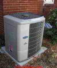
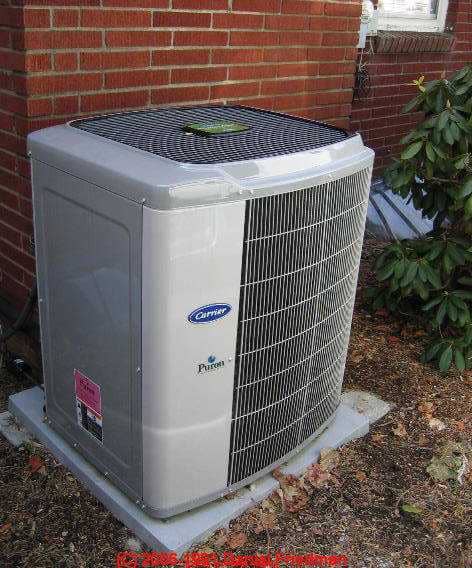
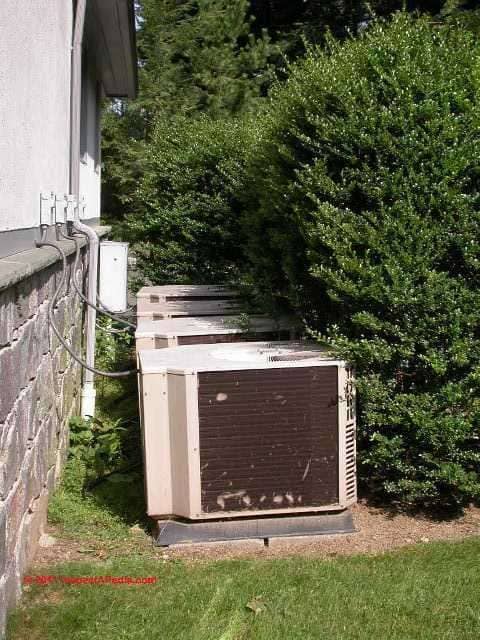
In a nutshell, the air conditioner compressor, condenser, fan unit is the "outdoor" half of an air conditioning or heat pump installation that uses a compressor motor (below right) to compress refrigerant gas to high pressure, sending the pressurized gas through cooling coils (condensing coils) where aided by air movement drawn by the condenser unit fan, the gas is returned to a liquid refrigerant state.
[Click to enlarge any image]
Article Series Contents
- AIR CONDITIONER/ HEAT PUMP LIFE EXPECTANCY - separate article
- COMPRESSOR / CONDENSER DIAGNOSTICS - separate article with step by step diagnosis,
- COMPRESSOR / CONDENSER OPERATION - how it works to heat or cool a building
- COMPRESSOR / CONDENSER UNIT COMPONENT PARTS - separate article
- COMPRESSOR / CONDENSER ENVIRONMENT & SAFETY WARNINGS
- COMPRESSOR / CONDENSER TYPES
- COMPRESSOR / CONDENSER VALVES
- COMPRESSOR / CONDENSER OILS
The process of compressing and then condensing the refrigerant back from a gas to a liquid also moves heat out of the refrigerant and into outdoor air. We explain this process in detail below.
The outdoor half of a typical air conditioning system (shown above) is a unit containing the refrigerant compressor and condensing coil and a cooling fan. In our photo the gray screened area covering one side of the condensing coil of the first compressor in this row is easily visible. The compressor motor itself (below-right) is not visible unless the covers of this unit are removed.
Topics discussed here:
Troubleshooting an air conditioner or heat pump compressor/condenser unit
- How does an air conditioner compressor and condensing coil work?
- What is the "Compressor" unit in an air conditioner or heat pump system?
- What are the components of the outdoor compressor/fan-coil unit on an air conditioner?
- Air conditioner or heat pump compressor motor crankcase heaters
- Air conditioner compressor problem diagnosis & repair guide
- Air conditioner condenser compressor fan diagnosis & repair
- Loss of air conditioner or refrigerator cooling capacity
- Types of air conditioner or heat pump compressors & compressor designs
- When is an air conditioner or heat pump compressor or fan/coil unit at or near end of its life?
Do I Need a New A/C or Heat Pump Compressor Unit?
If you think your air conditioner or heat pump compressor is not working, needs replacement or is "burned out",
see BURNED-OUT COMPRESSOR
Watch out: before assuming that the compressor motor or the entire HVAC compressor/condenser unit needs replacement, be sure you (or more likely your trained, qualified HVAC repair technician) has checked for simple and lower-cost problems such as a bad start/run capacitor, contactor relay switch, control board, or even just a loose wire or similar component.
Average Life of an Air Conditioning or Heat Pump Compressor ?
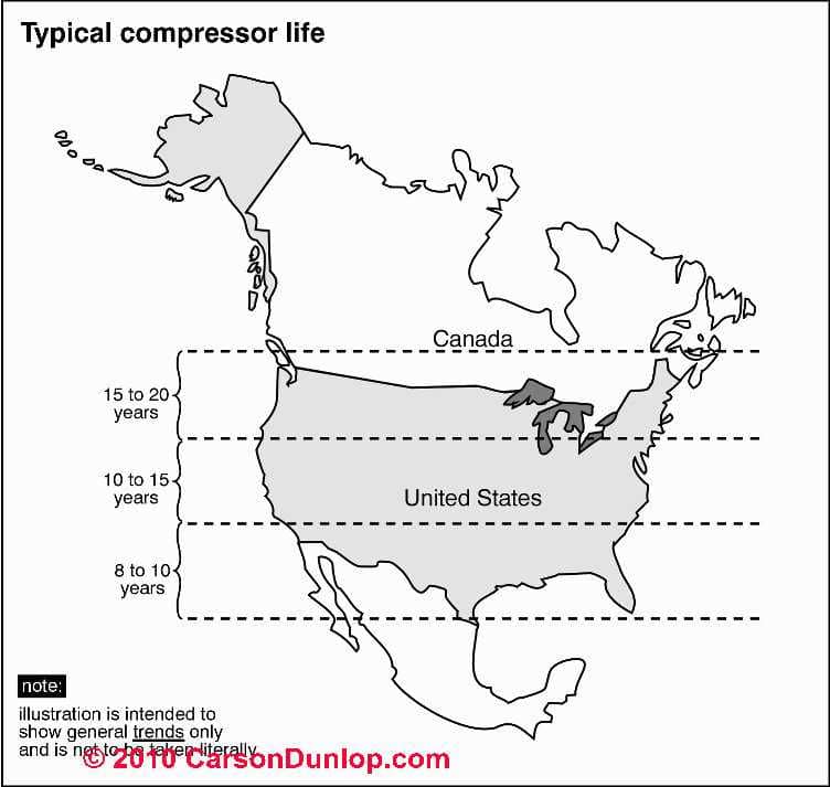
The typical life of an A/C compressor ranges from 10-20 years, though as you can see in Carson Dunlop Associates ' sketch, life expectancy of HVACR equipment depends on where the equipment is located.
Please see AIR CONDITIONER/ HEAT PUMP LIFE EXPECTANCY - separate article - for complete details including the factors that impact air conditioner or heat pump life.
How the Air Conditioning Compressor/Condenser Unit Works to Move Heat from Indoors to Outside
 In this article we will sketch and explain the internal parts of an air conditioner compressor motor and the A/C condenser unit such as the compressor, condenser, and key controls.
The A/C Compressor
The air conditioning compressor motor is a pump which draws sensible heat laden refrigerant gas from the building's indoor components (evaporator or "cooling coil" in the indoor air handler) through the larger diameter refrigerant suction line into the compressor where that pump compresses the low pressure refrigerant gas to high pressure and higher temperature.
Raising the coolant (refrigerant) temperature above outdoor ambient temperature causes heat to flow from the coolant (flowing out of the compressor and through the outdoor A/C condenser coil) into outdoor air. (Heat always flows from warmer to cooler substances).
Sensible heat and other terms are defined
at DEFINITION of HEATING, COOLING & INSULATION TERMS
Sketch courtesy of Carson Dunlop Associates, a Toronto home inspection, education & report writing tool company [ carsondunlop.com ].
As we explain
at THERMOSTATIC EXPANSION VALVES,
it is the flow restriction provided by a cap tube or by a TEV in the refrigerant piping system that allows the A/C compressor pump to raise the system pressure and thus increase the temperature at which the coolant changes state.
In other words, the TEV or cap tube allows the compressor to reduce refrigerant pressure on the LOW side of the metering device and raise refrigerant pressure on the HIGH side of the metering device.
Incidentally, A/C compressors can only accept and compress refrigerant in gas form. In fact the refrigerant vapor is superheated to be sure that there is no liquid at the pump - lest the pump be damaged. If liquid refrigerant were to flow into the compressor motor it would most likely cause catastrophic damage.
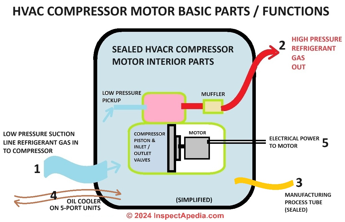
Even with the covers off you wont' see much of the actual air conditioner compressor motor: A/C compressor motors in residential and most commercial systems are hermetically sealed motors - that is, the motor is encased in a sealed steel can - all you'll see is a black metal container with metal (usually copper) tubing and some wires running to it.
That's the compressor motor. In our illustration of a hermetically-sealed residential compressor motor (above right), the smaller cylinder to the right of the compressor is a filter/dryer built onto this replacement unit.
The A/C Condenser
The high pressure high temperature refrigerant gas leaves the outdoor compressor and enters the outdoor condensing coil where it is cooled to a liquid state by the condensing unit fan that blows outside air across the condensing coil or by immersion of the condensing coil in cooling water in some designs.
The heat produced in these steps is transferred to the outside by a fan which blows outside air across the condensing coil. The liquid refrigerant is then able to return to the indoor components for cooling and dehumidifying the building interior.
Definition of an Air Conditioner or Heat Pump
An air conditioner or heat pump compressor is a basically a motorized pump which moves refrigerant gas from the indoor cooling coil (where it has evaporated to cool indoor air blowing over that coil) to the outdoor compressor/condenser where the gas is compressed and cooled back to a liquid form.
Refrigerant gas moves from the indoor air handler cooling coil to the outdoor compressor via the larger refrigerant "suction line".
Liquid refrigerant returns from the outdoor compressor/condenser to the in-building air handler and evaporator coil. Evaporating liquid refrigerant inside the indoor cooling coil cools and dehumidifies indoor air. Condensing refrigerant gas outdoors at the compressor/condenser effectively is moving heat from indoors to the outdoor air.
[During heat pump "heating" cycles the process is reversed, moving "heat" from outdoor air to the indoor coil.]
The diagnosis and repair of various defects in the air conditioning compressor/condenser unit are discussed in detail using the links
provided at the end of this article. Here is more detail about the components of the air conditioner or heat pump compressor/condenser unit:
Heat pumps are described separately and in more detail
at HEAT PUMPS.
Components of the Outdoor Portion of a Central Air Conditioning System
We have moved this discussion to a separate article. Please
see COMPRESSOR / CONDENSER UNIT COMPONENT PARTS
Air Conditioner or Heat Pump Compressor Unit Safety, Damage, & Environmental Warnings
Using Carrier installation instructions for the Carrier 24ANA unit as an example [2] and quoting:
[Compressor/Condenser] Unit Operation & Safety Hazard
Failure to follow this caution may result in minor personal injury, equipment damage or improper operation. To prevent compressor damage or personal injury, observe the following
- Do not overcharge system with refrigerant.
- Do not operate unit in a vacuum or at negative pressure.
- Do not disable low pressure switch
- Dome temperatures may be hot in scroll and bottom temperatures may be hot in recip.
Environmental Hazard Warnings - Failure to follow this caution may result in environmental damage.
Federal regulations require that you do not vent refrigerant to the atmosphere. Recover during system repair or final unit disposal.
Minimum Air Conditioner Compressor Unit Observations for an Air Conditioner Home Inspection Report
Example home inspection report language for an air conditioning compressor:
- The compressor and fan operated normally.
- The rated cooling capacity, estimated age and general condition of the unit are reported below.
OR - We did not operate this equipment because ... Therefore you should ...
[... explanatory text inserted by inspector]
Types of air conditioner or heat pump compressors & compressor designs
Sealed Compressors
Sealed air conditioning or heat pump compressors enclose both the driving electric motor and the mechanical compressor engine itself within a hermetically sealed "can".
Sealed compressors cannot be opened for repair in the field and are normally replaced entirely when needed.
The diagnosis of a sealed compressor relies on external observations and measurements such as current draws (amps) of the compressor motor and the operating pressures the equipment can achieve.
While a sealed hvac compressor unit can't be field-repaired, the unit can be replaced as an entire system, and in some cases the damaged unit can be traded in for an allowance on the replacement compressor. What are those three tubes seen welded or soldered to the hermetically sealed HVAC compressor can? There are three tubes you'll find on a typical sealed compressor unit:
- A suction line
(generally larger in diameter - low side line) - receives low pressure refrigerant gas from the cooling coil - A condenser line
(generally smaller in diameter - high side line) - sends high pressure refrigerant gas as compressor output to the condensing coil - A third line, blocked off, not used in the field - the process tube. T
his tube is used by the manufacturer of the compressor unit to test and charge the system. - 5-port HVAC or refrigeration compressors:
include a low side, high side, and process tube and two more tubes that send oil through an oil cooler or oil cooler condenser.
The oil cooler condenser lines will always be close together and close to the bottom of the unit (to pick up oil to be cooled) - that's how you can identify which of those tubes coming in and out of the sealed compressor are doing which jobs.
Watch out: if you are carrying a refrigerator or freezer in other than upright position,
that is if you have to place the unit on its side, place it so that the low side (suction side) refrigerant lines are facing "up" so as not to drain oil or liquid refrigerant into a line where it does not belong and where it may block a cap tube.
If you make a mistake and carry the appliance in the wrong position, you would be smart to leave it in the upright or operating position for a few hours before turning it on to avoid forcing a slug of oil into (and blocking)
the CAPILLARY TUBES
often used on home refrigerators or freezers.
Leaving the system upright allows oil that may have leaked into the refrigerant line to drain back into the compressor motor. If you turn on the system too soon the risk is that you push this oil into the cap tube where it may remain or be hard to get out or worse, you may leak oil into the reed valves where they will be damaged when the compressor motor is turned on.
Open type refrigeration compressors
Open type refrigeration compressors are commonly found on automotive air conditioning systems. The motor that drives the actual compressor (the mechanical engine that compresses refrigerant gas) is physically separate from the compressor and is located outside of it.
Typically a motor drives the compressor via a belt and pulley system (cars and some commercial refrigeration systems).
This is why you should run your automobile air conditioner from time to time even out of the cooling season - to lubricate the shaft seal around the compressor motor/pulley - that's a spot where refrigerant may leak out at a dried seal.
Semi-sealed HVAC compressors
Semi-sealed compressors can be disassembled and repaired, as can the open type above.
Air Conditioner / Heat Pump Compressor Valves - two common designs
All compressors have a suction and a discharge valve to control refrigerant flow through the unit.
Reed Valve refrigeration compressor motors
Often the valve is a reed design - in which case the bottom reed is the intake valve and a top mounted reed is the discharge reed or valve that discharges out through a noise muffler into the condenser piping and coil.
It is these valves that can be destroyed if liquid refrigerant is sent through the compressor.
Rotary valve refrigeration compressor motors - Frigidaire rotary compressor motors
[Click to enlarge any image]
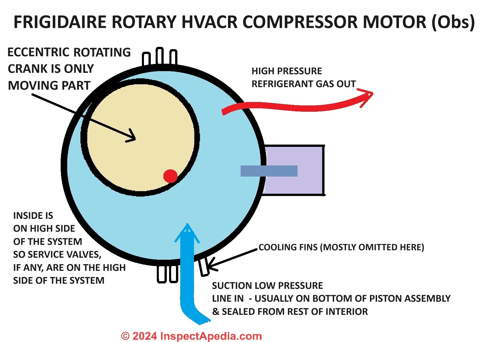
Some other refrigeration compressor valve designs are quite different from these simple reeds, including an old and very successful eccentric crank system: the rotary compressor motor design patented by Frigidaire™ and used in refrigerators for several decades.
This compressor motor design was used in a range of Frigidaire equipment and appliances including refrigerators and some air conditioners.
The durability of the design stems at least in part from its simplicity: a simple eccentric crank (see our sketch at left) is the only moving part in the motor.
On this compressor motor the inlet or suction line is generally found on the bottom of the unit, feeding directly into the bottom of the piston assembly and sealed from the rest of the chamber. The interior of the compressor chamber (sketch note and arrow at left) is on the HIGH side of the system. So service valves, if they are installed at all, are placed on the high side of the system there.
Frigidaire eccentric crank rotary refrigeration compressor motors were remarkably durable and reliable - we used a salvaged Frigidaire refrigerator compressor as our HVAC service vacuum pump for many years.
Air Conditioner / Heat Pump Compressor Motor Refrigerant Oils
Refrigeration compressor motors use 300 viscosity oils when working with refrigerants in the Freon family and 150 viscosity oils when working with other refrigerants. These are special oils that use a non-wax base such as Texaco Capella oil or oils by Virginia Chemical.
The refrigeration oil lubricates the moving parts of the compressor motor as it receives and compresses refrigerant gases.
at TYPES of AIR CONDITIONER or HEAT PUMP COMPRESSORS when we warned that carrying a refrigerator or freezer on its side could drain oil out of the compressor motor into the refrigerant lines where it might later become a problem by blocking the capillary tube or might enter reed valves causing valve damage, this is the oil we were talking about.
How to diagnose and fix an air conditioning system that is not working
If your air conditioning system won't work, use these easy A/C-heat pump diagnostic guides
Specific A/C or Heat Pump compressor diagnosis & repair procedures listed just below:
- A/C - HEAT PUMP CONTROLS & SWITCHES - identify and find all of the controls to be sure that the problem isn't something trivial
- BURNED-OUT COMPRESSOR
- CAPACITORS for HARD STARTING MOTORS that may get more life out of a compressor motor
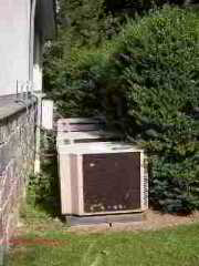
- CLEARANCE DISTANCE, HVAC - what happens if you block air flow around the compressor/condenser unit?
- COMPRESSOR / CONDENSER DIAGNOSTICS
- COMPRESSOR / CONDENSER INSPECTION CHECKLIST for a simple checklist for the outdoor compressor/condenser unit.
- CONDENSING COIL REPAIR REPLACE - discusses the replacement of the outdoor condensing unit coil
- CONTACTOR RELAY DIAGNOSIS & REPAIR - a bad switch or relay can prevent the outdoor compressor/condenser unit from running
- CONTROL CIRCUIT BOARD, A/C - a bad control board or circuit board in the outdoor compressor/condenser unit or inside in the air handler unit
- CRANKCASE HEATERS - are needed on the outdoor compressor motor in areas subject to cold or freezing weather. A failed heater can cause the compressor to push liquid refrigerant into the motor, ruining it.
- DEFECTS LIST - HEAT PUMP - and also DEFECTS LIST - HEAT PUMP SUBSYS list inspection points for heat pumps
- DIAGNOSTIC GUIDE A/C or HEAT PUMP - suggestions for diagnosing compressor or condenser fan and coil problems that can mean intermittent or totally lost cooling capacity of your system.
- ELECTRIC MOTOR DIAGNOSTIC GUIDE can help diagnose a compressor/condenser fan that's not working or an indoor air handler blower fan that's kaput
- FAN, COMPRESSOR / CONDENSER UNIT - if the fan on the outdoor compressor / condenser unit is not working properly
- HARD STARTING COMPRESSOR MOTORS - diagnostic tips can get a compressor running again or help determine that it needs to be replaced.
- AIR CONDITIONING & HEAT PUMP SYSTEMS - home - all diagnostic routines for the whole system
- SPLIT SYSTEM AC / HEAT PUMP REPAIRS
- TICKING NOISE DIAGNOSIS - traced to a condenser problem
- At LOST COOLING CAPACITY, our focus is on the case in which the air conditioning system seems to be "running" but not enough cool air, or no cool air at all is being delivered to the occupied space.
at OPERATING DEFECTS we take you through the major air conditioning problem symptoms and how to get the air conditioning system working again. - At A/C - HEAT PUMP CONTROLS & SWITCHES we explain the many electrical switches and controls that control an air conditioner or heat pump system. You'll need to check these if your air conditioner won't start.
Sketch of the condenser unit provided courtesy of Carson Dunlop Associates, a Toronto home inspection, education & report writing company.
List of air conditioning system diagnostic articles:
See our complete list of air conditioning system diagnostic and repair guide articles just below.
Since the failure of an air conditioner to turn on, loss of air conditioner cooling capacity, reduced air conditioning output temperatures, loss of cool air supply, or even loss of air flow entirely can be due to a variety of problems with one or more components of an air conditioner or air conditioning system,
after reviewing the lost air conditioner cooling diagnosis procedures described in this article, be sure to also review the diagnostic procedures at each of the individual air conditioning diagnosis and repair major topics listed just below.
If your air conditioning or heat pump system has lost its cooling capacity or won't start,
or if your air conditioning electrical bill has increased even though the system "on" time has not changed, select one or more of the diagnostic articles listed AT
AIR CONDITIONING & HEAT PUMP SYSTEMS - home -
Reader Comments, Questions & Answers About The Article Above
Below you will find questions and answers previously posted on this page at its page bottom reader comment box.
Reader Q&A - also see RECOMMENDED ARTICLES & FAQs
On 2019-12-18 - by (mod) -
Tibor
In the ARTICLE INDEX you'll find our article series on NOISE DIAGNOSIS that describes various sounds coming from heating and air conditioning equipment and the usual causes. That would be a great place to start. Don't hesitate to ask questions.
On 2019-12-18 by Tibor
My heat pump outdoor 2 blade condenser fan sounds like a helicopter and is getting louder
On 2019-10-11 - by (mod) -
In the ARTICLE INDEX you will see diagnostic articles such as
FAN WON'T RUN
On 2019-10-09 by sojal
fan not work but compressor work
On 2019-08-13 - by (mod) -
You might try the search box above to find our article on
Air conditioner short cycling
On 2019-08-13 by cheikh
mon compreseur sali 10minit es saret 30minit
On 2019-05-21 - by (mod) -
Farid
When a compressor motor has trouble starting in the manner you describe I suspect a refrigerant metering device clog - such as a clogged cap tube. If the compressor is facing high head pressure on its outlet side it can have trouble starting.
On 2019-05-21 by Farid
hi sir
i have samsung refrigerator model RS22FLMR that has problem
first the condenser fun (12 volts)not working ,,i replace it still not working , i replaced it with a 220volts fan it works good but the compressor start once when i powered the refrigerator on than wont start again until I un-plug and re-plug in the power cable so he start once again
what should i do plz
is it becose of dc 12 v fan not connected to board so compressor wont start again? or board problem or what u think about that .....
...
Continue reading at COMPRESSOR / CONDENSER DIAGNOSTICS - step by step diagnosis, or select a topic from the closely-related articles below, or see the complete ARTICLE INDEX.
Or see COMPRESSOR / CONDENSER REPAIR FAQs - posted originally at this article
Or see these
Recommended Articles
- AIR CONDITIONER WON'T START
- AIR HANDLER / BLOWER UNITS - home
- COMPRESSOR / CONDENSER DIAGNOSTICS - steps to check out the compressor/condenser unit
- COMPRESSOR / CONDENSER REPAIR - home
- COMPRESSOR / CONDENSER UNIT COMPONENT PARTS
- CONTROLS & SWITCHES on A/C or HEAT PUMP - what and where are all of the controls?
- DIAGNOSTIC GUIDE A/C or HEAT PUMP - First steps to diagnose an air conditioner or heat pump
- EDUCATION COURSES A/C / HEAT PUMP
- MANUALS & PARTS GUIDES - HVAC - home
- REFRIGERANT LEAK DETECTION
- SPLIT SYSTEM AC / HEAT PUMP REPAIRS - home
- TICKING NOISE DIAGNOSIS - traced to a condenser problem
Suggested citation for this web page
COMPRESSOR / CONDENSER REPAIR at InspectApedia.com - online encyclopedia of building & environmental inspection, testing, diagnosis, repair, & problem prevention advice.
Or see this
INDEX to RELATED ARTICLES: ARTICLE INDEX to AIR CONDITIONING & HEAT PUMPS
Or use the SEARCH BOX found below to Ask a Question or Search InspectApedia
Ask a Question or Search InspectApedia
Try the search box just below, or if you prefer, post a question or comment in the Comments box below and we will respond promptly.
Search the InspectApedia website
Note: appearance of your Comment below may be delayed: if your comment contains an image, photograph, web link, or text that looks to the software as if it might be a web link, your posting will appear after it has been approved by a moderator. Apologies for the delay.
Only one image can be added per comment but you can post as many comments, and therefore images, as you like.
You will not receive a notification when a response to your question has been posted.
Please bookmark this page to make it easy for you to check back for our response.
Our Comment Box is provided by Countable Web Productions countable.ca
Citations & References
In addition to any citations in the article above, a full list is available on request.
- In addition to citations & references found in this article, see the research citations given at the end of the related articles found at our suggested
CONTINUE READING or RECOMMENDED ARTICLES.
- Carson, Dunlop & Associates Ltd., 120 Carlton Street Suite 407, Toronto ON M5A 4K2. Tel: (416) 964-9415 1-800-268-7070 Email: info@carsondunlop.com. Alan Carson is a past president of ASHI, the American Society of Home Inspectors.
Thanks to Alan Carson and Bob Dunlop, for permission for InspectAPedia to use text excerpts from The HOME REFERENCE BOOK - the Encyclopedia of Homes and to use illustrations from The ILLUSTRATED HOME .
Carson Dunlop Associates provides extensive home inspection education and report writing material. In gratitude we provide links to tsome Carson Dunlop Associates products and services.
 | HOME | ABOUT | ASK a QUESTION | CONTACT | CONTENT USE POLICY | DESCRIPTION | POLICIES | PRIVACY | |
| © 2024 - 1985 Publisher InspectApedia.com - Daniel Friedman | |||||||||