InspectAPedia.com InspectAPedia®
Google
InspectAPedia
 

Free Encyclopedia of Building & Environmental Inspection, Testing, Diagnosis, Repair

Ask a Question or Search InspectAPedia

  • HOME
  • AIR CONDITIONING
  • DAMAGE ASSESSMENT
  • ELECTRICAL
  • EXTERIORS
  • HEATING
  • HOME INSPECTION
  • INTERIORS
  • PLUMBING
  • ROOFING
  • SEPTIC SYSTEMS
  • STRUCTURE
  • WATER SUPPLY
  • ENERGY SAVINGS
  • ENVIRONMENT
  • INDOOR AIR IAQ
  • INSULATION
  • MOLD INSPECT TEST REMOVE
  • NOISE
  • ODORS
  • SOLAR ENERGY
  • VENTILATION
  • EXPERTS DIRECTORY
  • CONTACT US


InspectAPedia ® Home

ELECTRICAL INSPECTION, DIAGNOSIS, REPAIR

AFCIs ARC FAULT CIRCUIT INTERRUPTERS
ALUMINUM WIRING HAZARDS & REPAIRS
AMPS VOLTS DETERMINATION
APPLIANCE EFFICIENCY RATINGS

BOOKSTORE - ELECTRICAL

Cadet & Encore Heater Recall
CIRCUIT BREAKER SIZE for A/C or HEAT PUMP
Classified CIRCUIT BREAKER WARNING
CUTLER HAMMER PANEL FIRE
CONDUIT, ELECTRICAL
CORROSION in ELECTRICAL PANELS

DEFINITIONS of ELECTRICAL TERMS
DIRECTORY OF ELECTRICIANS
DMM Digital Multimeter, How to Use

ELECTRIC HEAT
ELECTRIC METERS & METER BASES
ELECTRIC MOTOR DIAGNOSTIC GUIDE
ELECTRIC MOTOR OVERLOAD RESET SWITCH
ELECTRIC PANEL AMPACITY
ELECTRIC PANEL INSPECTION
ELECTRIC PANEL MOISTURE
Electric Power Frequency Table
ELECTRICAL BASICS
EMF RF FIELD & FREQUENCY DEFINITIONS
ELECTRICAL GROUND SYSTEM INSPECTION
ELECTRICAL SERVICE DROP
ELECTRICAL SERVICE ENTRY WIRING
ELECTRICAL TERMS
EMF RF FIELD & FREQUENCY DEFINITIONS

FIRE SAFETY Checklist, CPSC

GENERATORS, ELECTRICAL
GFCI PROTECTION,Testing GFCIs AFCIs

HEATING COST FUEL & BTU Cost Table
HEAT, ELECTRIC
HEAT TAPE USAGE GUIDE
Hertz - Definitions of KHz MHz GHz THz

KNOB & TUBE WIRING

LIGHTING, EXTERIOR GUIDE
LIGHTING, INTERIOR GUIDE
LIGHTNING PROTECTION SYSTEMS
LOW VOLTAGE BUILDING WIRING
LOW VOLTAGE TRANSFORMER TEST

MAIN DISCONNECT
MAIN DISCONNECT AMPACITY
MOISTURE SOURCES in PANELS
MULTI-WIRE CIRCUITS
MURRAY SIEMENS Recall

PHOTOVOLTAIC POWER SYSTEMS
PUSHMATIC - BULLDOG PANELS

REMOTE ELECTRIC POWER, PHOTOVOLTAIC
RUST in ELECTRICAL PANELS

SAFETY for ELECTRICAL INSPECTORS
SE CABLE SIZES vs AMPS
SIEMENS MURRAY Recall
SQUARE-D RECALLS

THERMAL EXPANSION of HOT WATER
THERMAL EXPANSION of MATERIALS

UNDERGROUND SERVICE LATERALS
VOLTS / AMPS MEASUREMENT EQUIP

WIND TURBINES & LIGHTNING

ZINSCO SYLVANIA ELECTRICAL PANELS

More Information

Photograph of  an older electrical service with multiple fuse componentsHow to find out the electrical service ampacity & voltage level entering a building: home page
     

  • AMPS VOLTS DETERMINATION - home - How to determine the size, capacity, or ampacity of electrical service at a building Visual inspection can tell the electrical service size - if you are thorough: see the following detailed articles for each of the factors that limit the actual amapcity of electrical servicve at a building:
  • Questions & Answers about how to determine the electrical capacity provided at a building: electrical system ampacity and voltage levels
  • References

Click to Show or Hide Related Topics

  • ELECTRICAL INSPECTION, DIAGNOSIS, REPAIR - home
  • ALUMINUM WIRING HAZARDS & REPAIRS
  • AMPS MEASUREMENT METHODS
  • AMPS VOLTS DETERMINATION - home
    • AMPS, LIMITING FACTORS
    • AMPS & SEC SIZES
    • AMPS & VOLTS, DETERMINE VISUALLY
    • AMPS MEASUREMENT METHODS
    • AMPACITY, MAIN DISCONNECT
    • DEFINITIONS AMPS VOLTS WATTS
    • ELECTRIC METERS & METER BASES
    • ELECTRICAL PANEL AMPACITY
    • VOLTAGE at the SEC
    • UNDERGROUND SERVICE LATERALS
  • AMPS MEASUREMENT METHODS
  • CIRCUIT BREAKER SIZE for A/C or HEAT PUMP
  • DIRECTORY OF ELECTRICIANS
  • DMM Digital Multimeter, HOW TO USE
  • DMM & VOM SAFETY
  • ELECTRIC METERS & METER BASES
  • ELECTRIC PANEL AMPACITY
  • ELECTRIC PANEL INSPECTION
  • ELECTRICAL DISTRIBUTION PANELS
  • MAIN DISCONNECT
  • SAFETY for ELECTRICAL INSPECTORS
  • SERVICE AMPACITY
  • SERVICE DROP
  • SERVICE ENTRY WIRING
  • TEST EQUIPMENT, ELECTRICAL
  • THERMISTORS
  • VOLTAGE DETECTION & MEASUREMENT
  • UNDERGROUND SERVICE LATERALS
  • VOLTS / AMPS MEASUREMENT EQUIP
InspectAPedia tolerates no conflicts of interest. We have no relationship with advertisers, products, or services discussed at this website.

How to determine building electrical service amps (ampacity) and volts (voltage):
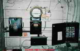
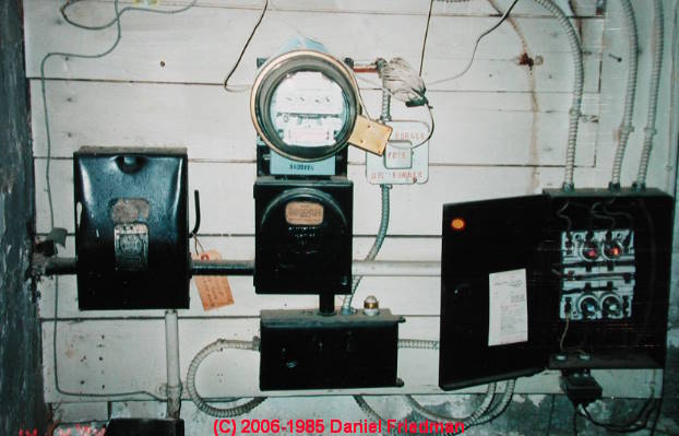
 this article series explains how to estimate the electrical service size, (or "electrical power" or "service amps") at a building by visual examination of the service entry cables, electric meter and meter base, electrical service panel, main switch, and other details. Visual inspection and use of digital multimeters(DMMs), Volt-ohm meters (VOMs), neon testers, and electrical inspection safety are discussed. Photographs and sketches illustrate electrical panels, meter bases, and electric meters. One of the most frequently asked questions at ASHI Education Seminars and Conferences is "How do I determine the service amperage?"

Green links show where you are. © Copyright 2013 InspectAPedia.com, All Rights Reserved. Author Daniel Friedman.

Residential Electrical Service Wire Sizes, Amps, Capacity

It's not as difficult as one may think to get a reasonable handle on the electrical service capacity (measured in amps) at a building without sophisticated analysis. But there are some pitfalls, and the process itself is inherently dangerous.

Fuse panel (C) Daniel FriedmanWe have divided the topic of how to make an accurate determination of the electrical system ampacity available at a building into the following articles:

  • AMPS VOLTS DETERMINATION - how to determine electrical service size - home
  • DEFINE AMPS VOLTS WATTS - basic electrical terms are defined: Amps, Volts, Watts
  • VISUALLY DETERMINE AMPS & VOLTS - Introduction to voltage and ampacity of an electrical service by looking
  • VOLTAGE at the SEC - how the service entry cable size limits the ampacity available at a building
  • VOLTS / AMPS MEASUREMENT EQUIP - how to use Volt-Ohm meters VOM's, Digital multi meters DMM's or multimeters
  • AMPS MEASUREMENT METHODS - how to actually measure amperage or current draw at a building, at an individual electrical circuit, or at an electrical appliance, device, motor, etc. Note that the measurement of current draw or amps or amount of electricity being consumed is an actual instantaneous measurement of actual electrial power use at the moment, not a measurement of the design capacity or capability of the electrical service at a building or in an electrical circuit.
  • LIMITING FACTOR sets AMPS - explanation of limiting factors on the electrical amps available at a property
  • SE CABLE SIZES vs AMPS - table of electrical service entry cable sizes and ampacity ratings
  • UNDERGROUND SERVICE LATERALS - table of underground electrical service entry cable sizes and ampacity ratings
  • ALUMINUM SECs & WIRING - special concerns with aluminum service entry cables
  • MAIN DISCONNECT - how to inspect the main electrical disconnect switch
  • MAIN DISCONNECT AMPACITY - how the main electrical disconnect switch limits service ampacity
  • PANEL AMPACITY - how to recognize age, type and volts/amps capacity of older electrical service panels or load centers
  • ELECTRIC METERS & METER BASES - recognize age, type and volts/amps capacity of older electrical meters
  • AMPACITY - the LIMITING FACTOR - list of five key items to inspect when determining the electrical service size

The articles from which much of this online material also appeared in abbreviated in a more abbreviated form were found in

  • ASHI Technical Journal, Vol. 2. No. 1, January 1992, "Determining Service Ampacity," Dan Friedman and Alan Carson, and the
  • ASHI Technical Journal, Vol. 3. No. 1, Spring, 1993, "Determining Service Ampacity - Another Consideration," Robert L. Klewitz, P.E., with subsequent updates and additions to the original text ongoing to 2/19/2006. Reprints of the originals and reprints of the Journal are available from ASHI, the American Society of Home Inspectors www.ashi.com.

Readers who are not sure of the definitions of Amps and Volts should see DEFINITIONS of ELECTRICAL TERMS.

Watch out: inspecting and/or touching electrical components is inherently dangerous and there is risk of shock or death by electrocution.

Electrical inspections are inherently dangerous to the inspector and potentially dangerous to inspection clients and building occupants.

People conducting these procedures must first be familiar with safe electrical practices before attempting any inspection of electrical equipment. Such familiarity is essential to protect all parties concerned. Inspectors: proceed at your own risk. See Safety Hazards and Safe Inspection Procedures at Residential Electric Panels.


Frequently Asked Questions (FAQs) about how to determine the service ampacity at a building - electrical service inspection procedures

...

Ask a Question or Search InspectApedia

Questions & answers or comments about how to determine the electrical capacity provided at a building: electrical system ampacity and voltage levels .

Ask a Question or Enter Search Terms in the InspectApedia search box just below.

Technical Reviewers & References

Related Topics, found near the top of this page suggest articles closely related to this one.

  • The Original Authors: Alan Carson is an ASHI Member, national home inspection educator, author and building failures researcher in Toronto, Ontario. Daniel Friedman, an original author of this article and the editor and producer of InspectAPedia where this article now appears is an ASHI Member, first ASHI Technical Committee chairman, editor and publisher of the ASHI Technical Journal, licensed home inspector, educator, and building failures researcher in Poughkeepsie, NY. Robert Klewitz is a licensed professional engineer, a professional home inspector, an ASHI Member, and has served on the ASHI Technical Committee as well as in other ASHI activities. His practice is in Issaquah, WA.
  • ASHI Technical Journal, Vol. 2. No. 1, January 1992, "Determining Service Ampacity," Dan Friedman and Alan Carson, and the
  • ASHI Technical Journal, Vol. 3. No. 1, Spring, 1993, "Determining Service Ampacity - Another Consideration," Robert L. Klewitz, P.E., with subsequent updates and additions to the original text ongoing to 2/19/2006. Reprints of the originals and reprints of the Journal are available from ASHI, the American Society of Home Inspectors www.ashi.com.
  • Carson, Dunlop &
Associates Ltd., TorontoCarson, Dunlop & Associates Ltd., 120 Carlton Street Suite 407, Toronto ON M5A 4K2. (416) 964-9415 1-800-268-7070 info@carsondunlop.com. The firm provides professional home inspection services & home inspection education & publications. Alan Carson is a past president of ASHI, the American Society of Home Inspectors. Thanks to Alan Carson and Bob Dunlop, for permission for InspectAPedia to use text excerpts from The Home Reference Book & illustrations from The Illustrated Home. Carson Dunlop Associates' provides:
    • Commercial Building Inspection Courses - protocol ASTM Standard E 2018-08 for Property Condition Assessments
    • Home Inspection Education Courses including home study & live classes at eleven colleges & universities.
    • Home Inspection Education Home Study Courses - ASHI@Home Training 10-course program.
      Special Offer: Carson Dunlop Associates offers InspectAPedia readers in the U.S.A. a 5% discount on these courses: Enter INSPECTAHITP in the order payment page "Promo/Redemption" space. InspectAPedia.com editor Daniel Friedman is a contributing author.
    • The Home Reference Book, a reference & inspection report product for building owners & inspectors.
      Special Offer: For a 10% discount on any number of copies of the Home Reference Book purchased as a single order. Enter INSPECTAHRB in the order payment page "Promo/Redemption" space. InspectAPedia.com editor Daniel Friedman is a contributing author.
    • The Home Reference eBook, an electronic version for PCs, the iPad, iPhone, & Android smart phones.
      Special Offer: For a 5% discount on any number of copies of the Home Reference eBook purchased as a single order. Enter inspectaehrb in the order payment page "Promo/Redemption" space.
    • The Illustrated Home illustrates construction details and building components, a reference for owners & inspectors.
      Special Offer: For a 5% discount on any number of copies of the Illustrated Home purchased as a single order Enter INSPECTAILL in the order payment page "Promo/Redemption" space.
    • The Horizon Software System manages business operations,scheduling, & inspection report writing using Carson Dunlop's knowledge base & color images. The Horizon system runs on always-available cloud-based software for office computers, laptops, tablets, iPad, Android, & other smartphones.
  • Mark Cramer Inspection Services Mark Cramer, Tampa Florida, Mr. Cramer is a past president of ASHI, the American Society of Home Inspectors and is a Florida home inspector and home inspection educator. Contact Mark Cramer at: 727-595-4211 mark@BestTampaInspector.com 11/06
  • Douglas Hansen, Robert Stead. Mark Cramer. Photographs: Daniel Friedman.
  • N. Srinivasan, MSEE, is a senior member of IEEE with 30 years experience in the electrical industry. Mr. Srinivasan is in Vienna VA.
  • Louis P. Babin generously contributed technical editing about the effects of doubling ampacity in an electrical circuit (September 2007)
  • Rust and Corrosion in Electrical Panels, A Study and Report on Frequency and Cause for Electrical and Home Inspectors at Residential Electric Panels
  • "Electrical System Inspection Basics," Richard C. Wolcott, ASHI 8th Annual Education Conference, Boston 1985.
  • "Simplified Electrical Wiring," Sears, Roebuck and Co., 15705 (F5428) Rev. 4-77 1977 [Lots of sketches of older-type service panels.]
  • "How to plan and install electric wiring for homes, farms, garages, shops," Montgomery Ward Co., 83-850.
  • "Simplified Electrical Wiring," Sears, Roebuck and Co., 15705 (F5428) Rev. 4-77 1977 [Lots of sketches of older-type service panels.]
  • "Home Wiring Inspection," Roswell W. Ard, Rodale's New Shelter, July/August, 1985 p. 35-40.
  • "Evaluating Wiring in Older Minnesota Homes," Agricultural Extension Service, University of Minnesota, St. Paul, Minnesota 55108.
  • "Electrical Systems," A Training Manual for Home Inspectors, Alfred L. Alk, American Society of Home Inspectors (ASHI), 1987, available from ASHI. [DF NOTE: I do NOT recommend this obsolete publication, though it was cited in the original Journal article as it contains unsafe inaccuracies]
  • "Basic Housing Inspection," US DHEW, S352.75 U48, p.144, out of print, but is available in most state libraries.


DEFINE AMPS VOLTS WATTS - Definitions of Volts, Amps and Phase - clearing up some confusion

See DEFINE AMPS VOLTS WATTS for full details about these and other electrical definitions.

In most places in the world, electrical service brought to a building is at either 240V or 120V. These numbers are "nominal," meaning that the actual voltage may be vary. Most modern buildings receive 240V service, a total achieved by the provision of two individual 120V incoming power lines.

Older buildings and electrical services often delivered only 120V. Knowing which voltage level is available is important, but knowing the voltage alone does not indicate the amount of electrical power available inside a building. For that we need to know both the service voltage at a building, and the service amperage (typically 100A or larger, but historically, 30A, 60A, 100A, 125A, and more recently 150A, or 200A depending on the power requirements at a building). Don't confuse service VOLTS (120/240 V) with service AMPS or WATTS - those terms are discussed next.

Amperage or Amps provided by an electrical service is the flow rate of "electrical current" that is available. Speaking practically, the voltage level provided by an electrical service, combined with the ampacity rating of the service panel determines how much electrical demand, or in another sense how many electrical devices can be run at one time in the building. Branch circuit wire sizes and fusing or circuit breakers used set the limit on the total electrical load or the number of electrical devices that can be run at once on a given circuit.

If you have a 100A current flow rate available, you could, speaking roughly, run ten 10 amp electric heaters simultaneously. If you have only 60A available, you won't be able to run more than 6 such heaters without risk of overheating wiring, causing a fire, tripping a circuit breaker or blowing a fuse.

Just as a 10 gpm flow rate of water through a pipe provides half the amount of water as a 20 gpm flow rate, 10 amps of current in a conductor provides half the energy as 20 amps of current. Some people find the "water analogy helpful in understanding these terms. "Amps" is a measure total current flow (or "gallons per minute" or "gpm" using the popular water analogy) available from an electrical service.

Volt, formally, is defined as the potential difference across a conductor when a current of one ampere dissipates one watt of power. This definition is not very helpful to consumers. Using the water analogy, volts is analogous to "pressure." Having higher "pressure" in a pipe (or electrical conductor) means that conductor is capable of delivering more energy to the user. We illustrate the concept of potential in these notes about electrical potential.

A ten-amp 240V electrical service is capable of delivering, speaking roughly, twice the energy to the end-user than a ten-amp 120V electrical service. So volts is a measure of the strength of an electrical source at a given current or amperage level. If we bring 100A into a building at 240V, we have twice as much power available as if we bring in 100A at 120V. Volts (continuing the same water analogy) is the "pressure" in an individual electrical conductor.

The total current ("gpm" or more properly electrical current measured in Amps) that will flow through a conductor is halved if the pressure (volts) is doubled. Twice the power or energy can be delivered on a # 12 conductor by doubling the voltage and holding the current to 20 amps. Doubling voltage and also doubling the amperage will deliver four times the power or energy.

In either case, if we exceed the current rating of an electrical wire, it will get hot, risking a fire. That's why we use fuse devices (or modern circuit breakers), to limit the current flow on electrical conductors to a safe level to avoid overheating and fires. - thanks to Louis Babin for technical review and edits to this text.

Is "240V" really exactly 240 Volts?: Don't expect a "240V" circuit to provide that exact voltage level. We've already said that "120V" and "240V" are "nominal" ratings, meaning that the actual numbers may vary. In a three phase circuit, even if you are using only two phases, the voltage between the phases is 1.732 x 120 = 207.6, or approximately 207 Volts and not 240 Volts. In various countries the actual voltage level varies around the nominal delivered "voltage rating" and in fact depending on the quality of electrical power delivered on a particular service, voltage will also vary continuously around its actual rating.

Most (but not all) modern electrical equipment can handle small voltage variations and differences without a problem. Sensitive electronic equipment may require that a voltage stabilizer be installed. For example a "240V" appliance can usually handle "208V" just fine.

The technical detail of how "240V" (or 207V if you prefer) is actually delivered to a building may be a bit confusing, so let's follow this carefully. In fact 240V delivered to a building does not mean that the individual service drop wires are carrying that voltage. Rather, 240V in the building is obtained as follows: the two "hot legs" are on different electrical phases provided by a step-down transformer at a neighborhood utility pole or box. Each service conductor on its own phase delivers 120V to the building.

The two (in this case) phases are arranged so that connecting a circuit across the two "hot legs" produces "240V" in for that circuit. An electrician or engineer, trained in safe volt-ohm meter (VOM) or digital multimeter (DMM) use can easily demonstrate this fact. Connecting a voltmeter from either incoming service conductor to ground will display 120V, and connecting a voltmeter across the two incoming 120V service conductors will display approximately 208V or 240V depending on just how the supplying transformer is designed.

[Technical details: Three phase power with the star (Y-connected) connected secondary and the neutral grounded, you get 208 Volts line-to-line, and 120 Volts line-to-neutral. With a single phase transformer (240 V secondary with a center tap and the center trap grounded), you get 120 Volts line-to-ground (neutral) and 240 Volts phase-to-phase (line-to-line). -- Thanks to N. Srinivasan for these clarifications].

Watts: How does "Watts" relate to the "Volts" and "Amps" discussed above? Briefly, Volts x Amps = Watts. To impress your friends, you can rearrange this equation using simple algebra or you can re-write it using Ohm's law. Ohms is a measure of electrical resistance, which also measures the heat that will be generated in a wire carrying a given current. Amps = Volts / Ohms. Given the two equations just cited, we can also write: Watts = Volts x (Volts / Ohms), which lets us write: Watts = Volts 2 / Ohms. (Hansen's various publications and his upcoming book point out variations of these formulae which are useful in discussing the heating of wires carrying current.)

Summarizing: 240V power delivered to a building in the U.S., Canada, and Mexico, and some other locations, means that the building is receiving two 120V lines which provide 240V for circuits connected across these two incoming wires, and which provides 120V for circuits connected from either of the individual incoming lines to ground. For heavier and commercial electrical power requirements, three and even four-phase electrical service may be delivered to a building, and in some applications, electrical equipment is designed to be fed directly by multiple phases.

You will not ordinarily see such service at a residential property, but one of the authors (DF) has encountered it in cases where there was a dental office in the basement of a home. The dentist's x-ray equipment required three-phase power. The tip off was the observation outside of four rather than three service conductors at the masthead, and in the main panel, the main switch was fed by three incoming service conductors rather than the usual two.

Determining the Electrical Service Ampacity and Voltage at a building by visual inspection

See VISUALLY DETERMINE AMPS & VOLTS for full details.

When a homeowner or client asks you "how much" electrical service is provided s/he needs to know the service ampacity and voltage. In the US and Canada service voltages are commonly (nominally, that is, not exactly) 240 volts at the electrical panel, a system which supports both 120V and 240V circuits in the building. Typically, two 120V hot wires entering the building provide 120V for circuits connected from an individual entering wire and the neutral bus, and 240V for circuits connected between the two incoming individual 120V circuits.

Older services, typically before 1940, may support only 120V and as little as 30-amps. We still find these services on small cabins and on a few old residences in the U.S., Canada, and Mexico and elsewhere. For normal residential use, excluding small vacation cottages, a 120V or 30A service would most likely be considered obsolete and has been since 1959 (Hansen). [NOTE: 1992 ASHI Standards of Practice, 8.2.1. While ASHI and other building inspection standards are updated periodically, the basic requirements addressed in this article should not change.]

Electrical inspections are inherently dangerous to the inspector and potentially dangerous to inspection clients and building occupants. People conducting these procedures must first be familiar with safe electrical practices before attempting any inspection of electrical equipment. Such familiarity is essential to protect all parties concerned. Inspectors: proceed at your own risk. See Safety Hazards and Safe Inspection Procedures at Residential Electric Panels.

VOLTAGE at the SEC - How to figure out Electrical Service Voltage by visual examination at the service entry

See VOLTAGE at the SEC for full details.

Visual examination of overhead electrical wires at the service entry. This procedure pertains to overhead wires, not underground conduit. Examination is made at the point of connection of the ELECTRICAL SERVICE DROP to the service conductors. In lay terms, the service conductors are also called the service entry cable or SEC. Underground wiring up to the building is called a service lateral. A 240V electrical service [three-wire figure at left] will include three wires connected to the building - the two 120V "hot" legs which together provide 240V, and a third grounded conductor.


A 120V service [second, two wire figure at left] will have only two wires, a 120V power line and a grounded line or neutral.

However simple visual examination from the ground is not a certain proof of voltage available in the building. In a few unusual circumstances, all three wires may be present but one of them may be disconnected at the utility pole or masthead. Such "mistakes" occur during temporary hookups in new construction or renovation.

Could there be 240V service to a building with only two wires? Yes but not normally in the U.S. Some Canadian rural properties served by long private wires may have only two overhead conductors on a 240 volt service. For these systems ground connections are made only at the building, not back to the utility company's lines. In the U.S. this would be unusual but be alert for it, especially at rural properties.

Table 1. Service Voltage Configurations
Number of Visible Wires at MastheadProbable Voltage
InsulatedUninsulated-Ground
11120
20120/240
21120/240
30 or 1120/240, 120/208 3-phase [1]
4 . 3 phase, need to measure volts [2]

Notes to Table:
1. This could also be a delta 3-phase with 3 120V legs; 3 phase power not common at residential properties.
2. 208 Volt service may be present on 3rd red wire.

VOLTAGE by EQUIPMENT - Determining Electrical Voltage (240V/120V) using a neon tester, a VOM, DMM, or Volt Meter

Neon Tester

See VOLTS / AMPS MEASUREMENT EQUIP for the full version of this section.

Instruments as simple as the neon-tester shown here or a digital multimeter (DMM), or an analog volt meter (volt-ohm meter) such as those made by Triplett, Fluke, and Simpson can be used to measure the voltage level between the two power feed lines to confirm the presence of 240 Volt service. (Some versions of this equipment can also be configured to measure amperage or amps).

Using a DMM, analog volt meter, or a neon tester, voltage between the two apparently "hot" wires in the panel will confirm 240-volt service. If only one cable is "hot" (testing cable to ground) it is a 120 V system. If both cables are "hot" to ground but there is no voltage between them it is a 120V system which has been "split" to look like 240V but it is not 240V. A volt meter is required to test for other voltage levels.

Safety Warning: The ASHI Standards of Practice and other home inspection standards for electrical inspections do not require the inspector to insert any instrument into the service panel. Therefore this testing is optional. It's also a dangerous procedure and should not be undertaken unless the person conducting the examination is trained and competent to avoid electric shock. If the inspector is not trained for this procedure s/he should never insert any instrument or tool into electrical equipment. See Safety Hazards and Safe Inspection Procedures at Residential Electric Panels.

Here are some basic types of electrical test equipment defined:

  • An ammeter measures current, expressed in amps
  • A voltmeter measures the potential difference (voltage) between two points
  • An ohmmeter measures resistance.
  • A multimeter combines these functions into one piece of equipment.
  • A neon tester simply measures for the presence of live electrical power.
  • An ohm meter measures resistance in a circuit or on a component and is not normally connected to a circuit carrying live voltage.
  • A continuity tester is a simple substitute for a more sophisticated ohm meter, and is used simply to confirm that there is electrical continuity on a circuit, that is, that it is not interrupted by a switch or open connection.

LIMITING FACTOR sets AMPS - Checking the Electrical Service amperage - what is the limiting factor

See LIMITING FACTOR sets AMPS for full details.

The safe and proper service amperage available at a property is set by the smallest of: the service conductors, the main disconnect fuse or switch, or the rated capacity of the electric panel itself. The inspector should consider all three of these and report any inconsistencies among them.

The main fuse/ circuit breaker (CB) is the only component which actively limits amperage at a property by shutting off loads drawing more than the main fuse rating. (Undersized conductors or service panels, if switched by a mismatched and oversized fuse or breaker, will permit more current to flow than their design intended, and can then overheat causing a risk of fire.)

The main breakers or fuses are permitted to be smaller (have lower overcurrent protection) than the capability of the service equipment (panel) and conductors (entrance cable). For example, a 2AWG copper service conductor (rated for 125 Amps, or in Canada for 120 Amps) to a panel using a 100-Amp main (service disconnect) is not a defect.["Residential Electrical Inspection," Douglas Hansen, ITA class material, Ver. 6.1 Oct. 1991, Los Altos, CA] You may want to point out to your client that such a service can be upgraded to higher amperage simply by installing larger main fuses/breakers.

Note that the main disconnect may be a fuse, breaker, or switch which is physically separate from the distribution panel. This is more common in older equipment installations and in very large commercial high-amperage installations.

common defect found in upgrades of older equipment is the installation of a new 100-Amp panel and main breaker while failing to replace the old 60-amp service entry cables. This is either incomplete work or work by an untrained person. Keep in mind that by service entry cables we're referring to the cables from the mast head (point of attachment of overhead wires to the building) down to the meter and from meter into the main switch or panel. Overhead wires, being cooled by open air, may be of a smaller diameter determined to be safe by the utility company for open air use.

Electrical Services providing less than 100 Amps are found in older properties but for a detached single-family dwelling these are considered obsolete and are a financing issue with some US lenders.[NOTE: NEC-230-42(b,1) and some FHA, VA, and private Banks in some states.] Services of 60 Amp capacity are still allowed in at least some Canadian areas and in the US for loads such as individual apartments. Inspectors should not write up 60-Amp services as a defect without first checking these points.

In cabins or similar vacation structures in the U.S. and Canada, and in buildings in some other countries such as Mexico, much smaller amperage services are often brought into the building.

Home Inspectors should make clear to all parties that generally, electrical defects are unsafe conditions, can be quite dangerous, and deserve prompt attention. One exception: an undersized service, if it is properly fused, will be inconvenient but is not itself inherently unsafe. For such systems the safety and fire risks come more often from the temptation of frustrated owners to subvert or bypass the safety devices the classic "penny in the fuse base" problem.

SE CABLE SIZES vs AMPS - How to Inspect Electrical Service entrance cables for Ampacity, Voltage, Condition

See SE CABLE SIZES vs AMPS

The amperage provided by the electrical service entrance cable is a function of its materials and diameter. Often the actual cable type and size is printed right on the cable insulation. Otherwise some rough measurements of cable diameter are in order.

If, inside the panel, the inspector could see the ends of the entrance cable [Figure at left], measure metal wire diameter, and if the inspector knew the manufacturer of the cable and its specifications, a certain identification of the cable's ampacity could be made.

However a safer, faster and common practice is to examine the exterior of the cable at a point outside of the electric panel. Make sure you look at both outside (mast head down to meter) and inside (from meter into service panel).

They may be different! Inside the panel, stripped of ground and insulation, you may see only wires as in Figure 3. Don't confuse guides for external measurements of the whole cable with in-panel measurements of the wires themselves.

We use a plastic vernier caliper or other non metallic instrument to measure external (insulated) width of the whole cable as a reasonable guess at wire ampacity. Some inspection tool companies sell, and others give-away a plastic "wire gauge" with notches labeled to tell electrical inspectors the cable size for aluminum and copper SECs. Or you can make your own.

But this method is not precise. Plastic insulated cable, for example, is often thinner in total thickness than older fabric-covered cable. Look at the table of wire dimensions in the accompanying article. Fortunately for building inspectors, even though wire thickness varies among manufacturers, you can generally find the measurement closest to one of the standard sizes and you're likely to be correct. [See sidebar, Electric Wire Sizes in this article]

UNDERGROUND SERVICE LATERALS - delivering current to a building

See UNDERGROUND SERVICE LATERALS

Electrical Services provided through underground conduit do not permit visual inspection of the service conductor prior to the electric meter and actual conductors are visible only in the service panel. It is possible to guess at the cable run in a conduit by the diameter of the conduit itself [Table 2.] But for conductors from the utility company's drop to the meter, conduit size sets only the maximum conductor that could be contained, not necessarily the actual size.

Table 2. Service Conductors in Conduit
Service AMPS-USA Rigid non-metallic conduit or iron pipe diameter
303/4"
1" in Canada
601"
1001 1/4"
1502"
2002"

Notes to Table:
Pipe sizes are nominal; for copper wires.

Do not attempt to open the meter base. If you are unable to determine the wire ampacity because there is no view, or because its dimension is not one with which you are familiar, say so.

ALUMINUM SECs & WIRING - Aluminum Service Cables and Wiring in buildings for Electrical Service Delivery

See ALUMINUM SECs & WIRING

In both branch circuit and entrance cable wires, the permitted wire gauges for copper are normally one size smaller than for aluminum used at the same ampacity rating. This is because copper is a better conductor than aluminum. Aluminum wire must be larger to safely carry the same current as copper.

Fire and Safety Issues with Aluminum Electrical Wiring

There are important fire safety issues concerning the presence of aluminum branch circuit wiring in buildings - not discussed in this article. Solid aluminum branch conductors are no longer used in new wiring.

Aluminum service entrance cables and aluminum single-purpose high-amperage circuits [NOTE: Such as for auxiliary sub-panels, central air conditioning or electric ranges.> are commonly installed in many communities.

Many new electric service panels use plated aluminum parts. According to some experts risks remain even with these permitted applications in both the US [see "Reducing the Fire Hazard in Aluminum-Wired Homes," Jesse Aronstein, Ph.D., Wright Malta Corporation, Ballston Spa, NY, 1982] and Canada [see "Overheating Failures of Aluminum-Wired Special Service Connectors," Jesse Aronstein and Wilfred E. Campbell, IEEE Transactions on Components, Hybrids, and Manufacturing Technology, Vol. 4 CHMT-6, No.1, March 1983.] The risks of poor connections and fire hazards for aluminum SEC wiring are reduced by proper abrasion of the connected wires, proper tightening of the connector, and use of a special anti-corrosion flux compound. These articles are available at the Aluminum Wiring Information Website cited just below.

As recently as June 2006 we received a report of a major house fire which the owner asserts began at an overheating electrical service entry cable connector. Our opinion is that because the number of these connections is less than on a branch circuit wire, and possibly for other technical reasons involving the performance of multi-stranded aluminum wire, the risk of a fire is probably statistically less than with solid conductor branch circuits. It would appear that the risk is not as low as with copper service entry cables.

More Reading:
The Aluminum Wiring Information Website for a thorough discussion of aluminum branch circuit wiring concerns in the U.S. and in Canada as well. [There is disagreement among professionals about the Canadian risk and failure rate. Ontario Hydro and some Canadian inspection professionals do not acknowledge a significant risk from aluminum wiring in Canada. However the Scarboro development in Ontario demonstrated that failures and fires have occurred in that country. --DF]

MAIN DISCONNECT AMPACITY - How to find the Main electrical service disconnect ampacity determination

See MAIN DISCONNECT AMPACITY

We look for an indication right on the switch. If no markings are present, document that observation. Markings in or on the panel box about ampacity indicate what current limiting device (such as a fuse) size could or should be installed, not what fuse or breaker size is actually present.

Look at the fuse/breaker for this data. Beware: I [DF] have found buildings with mismatched SEC and main panel switch, with errors in both directions: in one instance a new 100A SEC was installed but connected to an old 60A service panel (safe but not delivering 100A to the building). In a second case, a new 150A panel was installed but connected to an old 60A SEC (unsafe).

On some fuse systems the main fuses, usually a cartridge type, may be visible and the fuse ratings may be read on the fuse itself. [Figure at left] There are varying opinions among inspectors about pulling out a fuse block to read a hidden fuse value.

Mark Cramer reminds us that You can usually see the color of the fuse through the little hole. Also note that you generally can't put a fuse that's too large into a block. For example, you can't put a 150 amp fuse in a 60 amp block.

However I have seen smaller fuses inserted in larger-fuse blocks using an adapter, and I've seen copper tubing and copper pipe inserted where a fuse belonged! So if you can't see the fuse, it's risky to assume the right thing is in place. In Canadian and in some US panels fuses can be changed individually and may be more visible.

In an occupied building we do not pull a fuse or shut off any component without permission. While these devices are designed to be pulled by the homeowner and thus fall under ASHI's definition of "normal user or operator controls," we've seen and had reports of accidents including broken fuse pullout blocks, arcing, loss of power, and angry owners whose computers or kidney dialysis machines were in operation.

We do pull fuses in unoccupied buildings and may pull fuses in an occupied building with permission, provided in both cases our visual inspection of the equipment does not reveal any obvious unsafe condition. On the occasion when we pulled a fuse which disintegrated all parties agreed that it was better to discover the need for that repair now than in an emergency when power was needed.

If you find a fuse smaller than the maximum permitted by the conductors and panel equipment you should inform your client. But this is not a defect any more than it is unsafe to screw an 60-watt light bulb into a light designed to permit 100 watt bulbs.

If you cannot see the actual fuse, you may be able to see a rating on the fuse holder itself. However be warned that there are methods (not recommended) for modifying fuse holders to carry fuses other than those intended. You may even find pieces of copper pipe used as "jumpers" to replace the original fuses. These modifications are unsafe. If you do not pull the fuse and cannot see the ampacity, report this limitation to your client.

Electrical PANEL AMPACITY - Inspecting Electrical Service Panels for Ampacity

Many safety concerns attend this step. See Safety Hazards and Safe Inspection Procedures at Residential Electric Panels. More safety guidelines are in other publications. Do not attempt to open an electric panel without making yourself familiar with safe procedures.

Do not open or even touch electrical equipment if you find dangerous conditions, or simply uncertain conditions which give cause for alarm.

If you elect not to examine a component, indicate to your client that you did not inspect the component, explain why, and recommend appropriate steps to make access and inspection safe and possible. Document this information in your report.

See PANEL AMPACITY

HOW TO ESTIMATE - Electric Service Panel Ampacity

See PANEL AMPACITY - HOW TO ESTIMATE for full details.

We look for a tag (usually paper) or embossed rating (on fuse pull outs) on the panel itself which often includes the amperage rating of the panel. This information is usually present in newer panels on a panel side, or on the panel cover.

Home inspectors or electrical inspectors who touch electrical wires or move them in order to better read the data tag are performing a dangerous act.

Actual dimensions of an electric panel are not a reliable determinant of ampacity. For example, many larger panels can be fitted with a variety of bus-bar and main switch assemblies of varying ampacity.


Older 30-amp panels typically have round 15-amp or 20-amp fuses installed on both hot and neutral conductors,[Figure at left] and sometimes a separate main fuse switch.

There are safety issues with fused-neutral equipment - not discussed in this article.


Simpler 30-amp panels like the smaller four-fuse panel shown at immediate left are usually auxiliary rather than main service panels in most buildings.

An exception which the author's have found is that this panel was used as a main service for small lake and other remote cottages.

Where such buildings have in more recent years had additional electrical circuits installed, for use of electric heaters, for example, such panels are often overcrowded and very often the individual circuits are over fused - a fire hazard.


Older 60-amp panels [first panel shown above] and some 100-amp panels [Figure at left] often have a single or a pair of BakeliteTM fuse holders, one marked "main," the other marked "range." In typical installations, the "main" fuse pullout shuts off power in the panel except the range circuit. This main should contain 60-amp or smaller fuses.

Both main and "range" pullouts must be removed to cut all power.

The example at left used a 60A fuse supplying the lighting circuits (fuses in row along the panel bottom) and a 40A 240V appliance circuit is supplied by the "range" fuse pair.


The next panel shown at left is a 100-amp (or larger) fuse panel using a main fuse holder centered in the top of the panel.

The two fuse holders for two 240V circuits at the panel bottom are not mains and were often used to supply a range circuit and clothes dryer circuit, or range and sub panel circuits.

125-amp CB panels are often fitted with a 100-amp main disconnect CB or fuse-pair. In this case the electrical inspector should ignore the larger equipment panel size (perhaps indicated by an inside-panel label) and instead s/he should rate the electrical service ampacity based on the main CB or fuse-pair.


Based only on apparent panel size and provision for 24 circuits, this larger panel at left, showing a modern main CB at the top and two 12-breaker columns is at least a 100 Amp box, maybe 150 Amps.

The inspector had better check the service conductors, main circuit breaker, and panel label.


In the multi-pullout 100-amp fuse panel shown next at left, all four of the top pullouts are mains.

The top two switch 240-volt appliances and the bottom two power the left and right hand groups of screw-in type fuses in the bottom of the panel. (The upper left-hand 240 V appliance circuit's fuse is not connected so is not in use.)

All four of these fuse sets in a panel of this design should be labeled mains.

This is a tougher one since, as Hansen points out, [Hansen, op. cit.] the sum of the ratings of the different disconnects may exceed the capacity of the conductors.

For example you can have a 125A service with two main disconnects, one rated at 100 amps and one rated at 50 amps. In this case we'd look at the rating of the service conductor and the service equipment (panel) for help.

ELECTRIC METERS & METER BASES - Inspecting Electric Meters & Meter Bases - Another Consideration When Determining Service Ampacity

See ELECTRIC METERS & METER BASES

Notice: June 2006 editors's note: recent discussion among various experts and one of the original reviewers (D.H.) raises question about the accuracy of estimating service size in volts or amps by inspecting modern electrical meters. While some of the cases illustrated here remain accurate, these methods may be unreliable when examining modern electrical meters and meter bases. This subtopic remains under review.

The photos and text below will assist in identifying a variety of electrical meters and service panels of various ages and capacities.

An article in the Winter, 1992 ASHI Technical Journal discussed the procedure and considerations for inspectors to determine the service ampacity of an electrical system. That article indicated that the safe and proper service amperage available at a property is set by the smallest of the service entrance conductor, the main disconnect fuse or circuit breaker, and the rated capacity of the panel itself.

These are also issues of concern for the electrical contractor installing the service. ASHI Technical Journal, Vol. 3. No. 1, Spring, 1993, "Determining Service Ampacity - Another Consideration," Robert L. Klewitz, P.E.

A Broad View of Service Ampacity Determination Must Also Consider Electric Meters & Meter Bases

The concerns of inspectors must be broad in scope. Inspectors must look at the entire system, some of which may be dictated by the electric utility, and may not be a concern of the wireman or National Electrical Code. [National Electrical Code, article 90-2(b)(5)]

Because of this, there is one additional item that must be considered when determining service ampacity. This item is the rating of the electrical meter base and the meter itself. Many times there will be no sure way of determining this rating on a visual inspection, since the rating sticker would typically be inside the meter base and would require pulling the meter off to see it. However, there are some guidelines and "rules of thumb" that can be used.

Electric Meter Bases as Indicators of Electrical Service Ampacity

See ELECTRIC METERS & METER BASES

Warning: Looking at meter bases and meters to guess at ampacity is questioned by some experts as too unreliable.

Click for LARGER PHOTO Systems that have been installed for the last 20 years or so will typically have a rectangular meter base of various sizes as shown in the rectangular-base meter at left. These are usually compatible with 200 Amp services, although undoubtedly there are exceptions to this.

NOTE: Did you notice the measuring tape marking the 3" gap between the siding "J" channel and the top of the meter? This electric meter had been pulled downwards by backfill settlement which pushed down the horizontal portion of the buried conduit bringing the service laterals to the building.

I [DF] considered this a reportable defect as it was possible that the buried conduit was broken and subject to water entry from this condition and since the wires entering the building panel from the meter box have were disturbed. However M. Cramer points out that most conduit is not continuous, so breaking it is not really an issue aside from damage to conductors underground.

In 1976, an Underwriters Laboratory (UL) ruling required that all new meter bases be "continuous rated for 200 Amps," otherwise only 70% of the actual rating would be considered usable, (i.e., a 200 Amp meter base that was not "continuous rated" could only be used on a 160 Amp or smaller service). Inspectors can probably assume that a rectangular meter base is compatible with the system it is serving, unless a major change or a new panel has been installed.

Square meter bases such as the unit being pointed to with great caution by an ASHI Headquarters staff member on a field trip in the photo at below-left were normally rated at 100 Amps.

Later generations of them were sometimes rated at 125 Amps. Older systems that were installed 30 or more years ago may be served by a square meter base with a round meter mounted on top of the square base as seen in the next photo at below-center - often called an "A-base" meter. Still older systems used the round meter base shown at below right. Round meter bases originally were rated for 60 Amps when installed 50 or more years ago. (Later generations of round meter bases were rated at 100 Amps.) These meters can have a NMC main service wire running to and from them, or the wire may be installed in conduit.

Click for LARGER PHOTO Click for LARGER PHOTO Click for LARGER PHOTO


Click for LARGER PHOTO The photo at left is a nice collection of main switch, meter base, round meter above the square base, and a four-fuse "main" panel. What do you think the ampacity was of this electrical meter, main switch, and fuse panel system?

ELECTRIC METERS - as Indicators of Service Ampacity

See ELECTRIC METERS & METER BASES

The meter itself is also a consideration when determining the service ampacity of an electrical system. Most modern meters for single family homes have the designation "CL200" somewhere on their face, which indicates they are rated for up to a 200 Amp service. The CL200 rating may not limit these to 200 amps. Cramer reports finding larger services with CL200 meter bases.

Inspectors will also occasionally find a "CL10" meter which is a transformer-rated meter for large houses with larger electrical systems or two separate main panels.

Some older meters have other designations such as "15 Amps" on their face. This was their test rating. These meters are only usable on systems up to 100 Amps.

Some older meters were also designated as "30 Amps" on their face and these are compatible with 200 Amp services. For example, one may occasionally find an older house with an upgraded 200 Amp service that still has an old 15 Amp meter plugged into a new meter base. This meter is not really compatible with the system and should be replaced. Since the responsibility for the meter varies throughout the country, inspectors should contact the local electric utility for their policies and procedures concerning meters.

INSPECTING METERS & BASES - Inspecting Electric Meters and Electric Meter Bases

See See ELECTRIC METERS & METER BASES

Electrical inspectors need to examine the meter and meter base and should take them into account when determining service ampacity. The elements to consider are:

  1. The size/rating of the service entrance conductors.
  2. The rating of the panel.
  3. The rating of the main breaker, if any.
  4. The rating of the meter base.
  5. The rating of the meter.

The weakest or smallest of these five items will determine the service ampacity of the system. This inspection will also determine whether or not all parts of the system are compatible with each other and proper for the installation. There are other good reasons to look at the meter base and meter during your inspection. Occasionally one may discover other meter defects or concerns:

  1. Moisture or water inside the meter face and/or rust on the meter base.
  2. Missing knockouts on the meter base.
  3. Broken or cracked conduit or hubs.
  4. Loose connections of the meter.
  5. Inadequate fastening of the meter base and/or mast to the building.

The building inspector's responsibility goes beyond that of the electrical contractor and the local electric utility. Because of this, the inspection of the meter and meter base is an important part of your electrical system inspection, and must be done carefully. This will help to protect your client's interests and will help fully inform them about electrical system defects and the proper service ampacity of the house they are considering to buy.

AMPACITY - the LIMITING FACTOR - Summary: What is the limiting factor that determines the actual electrical service ampacity at a building?

See AMPACITY - the LIMITING FACTOR

Remember you're looking for the limiting factor in determining ampacity.

  1. electrical service entry cable or "SEC" (we do not generally consider the overhead or service lateral wiring)
  2. electric meter
  3. electric meter base
  4. main electrical power switch fuse/circuit breaker
  5. electrical panel

Click for LARGER PHOTO Inspectors attempting to determine (or estimate) the ampacity of the electrical service at a building should report their determination.

If conditions limit your inspection, such as in the photo at left, you can't identify the capacity of all the components described in the text above. In that case you should report which determining components were or were not visible or identifiable. We don't hesitate to tell our clients what the electrical service size (ampacity) appears to be. But we make quite clear the difference between what we know and what we think.

Books & Articles on Building & Environmental Inspection, Testing, Diagnosis, & Repair

  • Our recommended books about building & mechanical systems design, inspection, problem diagnosis, and repair, and about indoor environment and IAQ testing, diagnosis, and cleanup are at the InspectAPedia Bookstore. Also see our Book Reviews - InspectAPedia.
  • Home Reference Book - Carson DunlopThe Home Reference Book - the Encyclopedia of Homes, Carson Dunlop & Associates, Toronto, Ontario, 25th Ed., 2012, is a bound volume of more than 450 illustrated pages that assist home inspectors and home owners in the inspection and detection of problems on buildings. The text is intended as a reference guide to help building owners operate and maintain their home effectively. Field inspection worksheets are included at the back of the volume. Special Offer: For a 10% discount on any number of copies of the Home Reference Book purchased as a single order. Enter INSPECTAHRB in the order payment page "Promo/Redemption" space. InspectAPedia.com editor Daniel Friedman is a contributing author.

    Or choose the The Home Reference eBook for PCs, Macs, Kindle, iPad, iPhone, or Android Smart Phones. Special Offer: For a 5% discount on any number of copies of the Home Reference eBook purchased as a single order. Enter INSPECTAEHRB in the order payment page "Promo/Redemption" space.

  • GO TO Carson Dunlop's Home Study Course Information - How to Become a Home Inspector: Carson Dunlop's nationally recognized Home Study Course, selected by ASHI the American Society of Home Inspectors and other professionals and associations. This website author is a contributor to this course.
  • GO TO Carson Dunlop's Home Study Course Information - How to Become a Home Inspector: Carson Dunlop's nationally recognized Home Study Course, selected by ASHI the American Society of Home Inspectors and other professionals and associations. This website author is a contributor to this course.
  • GO TO Carson Dunlop's Home Study Course Information - How to Become a Home Inspector: Carson Dunlop's nationally recognized Home Study Course, selected by ASHI the American Society of Home Inspectors and other professionals and associations. This website author is a contributor to this course.
    Building inspection education & report writing systems from Carson, Dunlop & Associates Ltd
  • Recommended books on electrical inspection, electrical wiring, electrical problem diagnosis, and electrical repair can be found in the Electrical Books section of the InspectAPedia Bookstore. (courtesy of Amazon.com)
  • ...

HOME ABOUT CONTACT COPYING DESCRIPTION POLICIES PRINTING PRIVACY © 2013 Copyright InspectAPedia.com