
InspectAPedia® FREE Encyclopedia of Building & Environmental Construction, Diagnosis, Maintenance & Repair |
Question? Just ask us! InspectAPedia
|
 Electrical Outlet Installation Wiring Procedures & Codes
How to wire an electrical receptacle, wall plug outlet: complete installation details
- POST a QUESTION or COMMENT about how to install and wire electrical outlets or receptacles in buildings.
How to install an electrical receptacle - electrical outlet wiring procedure:
Starting here, this article series describes how to choose, locate, and wire an electrical receptacle in a home
Electrical receptacles (also called electrical outlets or "plugs" or "sockets") are simple devices that are easy to install, but there are details to get right if you want to be safe.
This article series explains eletrical receptacle types (also referred to as wall sockets, outlets, or "plugs" by non-electricians), receptacle grounding, connecting wires to the right receptacle terminal screws, electrical wire size, electrical wire color codes, and special receptacles for un-grounded circuits.
InspectAPedia tolerates no conflicts of interest. We have no relationship with advertisers, products, or services discussed at this website.
Electrical Outlet Wiring Instructions for Homeowners & DIY Repairs
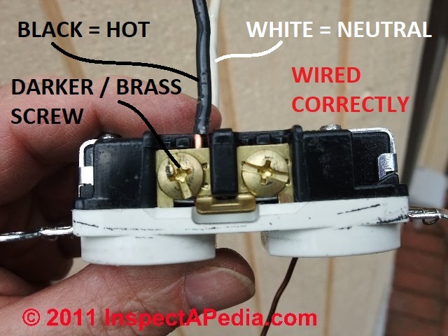 Our photo (left) shows the black or "hot" wire connected to the brass-colored screw on an electrical receptacle.
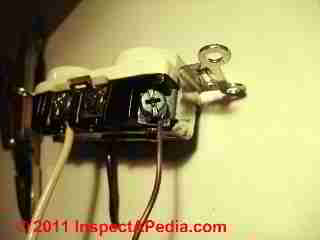
Our photo at page top illustrates other wire connections shown out of the electrical box and thus is not an example of a proper electrical outlet installation.
We summarize the electrical connections for wiring up a receptacle just below.
Step by step illustrated details for electrical "outlets" properly called electrical receptacles, are
at ELECTRICAL RECEPTACLE CONNECTION DETAILS.
How to add an electrical outlet in a home - the basics of wiring an electrical receptacle
We use the proper term electrical receptacle to describe the "wall plug" or "wall outlet" into which you will insert a two-prong or three prong plug to connect an appliance, lamp, etc.
Technically in the electrical code, an "outlet" is any place in where you provide a junction box and electrical wires to which something can be connected: a light fixture or an electrical receptacle, for example.
With a few simple tools, electrical wiring of an electrical receptacle is not difficult, but there are a few details to get right in order for the electrical receptacle to be safely installed.
Why might we need to add an electrical receptacle in a building?
- Convenience: we'd like to be able to plug in more electrical devices at some spot, say at a home office;
- Safety: we need to plug in more devices at some location and we don't want to risk tripping someone or starting a fire by using extension cords;
- Function: we need to plug in more devices at some location in a building, or we need to plug in a new high-current using device in a building, and we find we keep blowing fuses or tripping a circuit breaker;
in this case we want to add a whole new circuit, from electrical panel to the location where we need the outlet, so that we can deliver adequate electrical power without blowing fuses or tripping circuit breakers.
 On a conventional 120-volt "two pronged" electrical outlet that accepts grounded plugs (two prongs plus the rounded center ground connector prong), your circuit will have three wires:
- The white "neutral" wire - this wire is connected to the silver screw on the electrical receptacle, often labeled "neutral" . You can see our white neutral wire connected to a silver screw on the receptacle in our photo, below-left.
- The black "hot" wire - this wire is fed from the circuit breaker to deliver power to the receptacle, and it connects to the brass or bronze-colored screw on the receptacle, often labeled "hot" or "live".
You will see the hot black wire connected to the bronze or darker-colored screw on the receptacle shown at below right. The receptacle we used for these photos happens to be a 20-A rated device that permits the wire to be inserted straight into a clamp that is tightened against the wire by the screw. - The red "hot" wire - this wire is not normally present nor used in a 120VAC electrical reptacle wiring hook-up. However a live red wire may be present in the electrical box. If this wire is used it will most commonly be in one of the following situations:
- The receptacle is in a 4-receptacle gang box being fed by two separate 120VAC circuits / wires from opposite sides of the electrical panel, or at least from two different electrical circuits/breakers in the panel.
A 4-receptacle gang box is often installed in a kitchen or workshop where users want to be able to plug multiple appliances or tools in at the same location without overloading a single circuit - so two different circuits are provided.
In this case two of the receptacles will be fed by one circuit (black hot wire) and two additional receptacles may be fed by a second circuit (red hot wire). Depending on local electrical practices, there may also be two separate white neutral wires (or the neutral may be shared) - The receptacle is a 240-Volt electrical receptacle - in which case it won't look like the wall receptacles shown and discussed in this article.
See ELECTRICAL RECEPTACLE TYPES - for photos and examples of 240V and other types of electrical receptacles.
- The receptacle is in a 4-receptacle gang box being fed by two separate 120VAC circuits / wires from opposite sides of the electrical panel, or at least from two different electrical circuits/breakers in the panel.
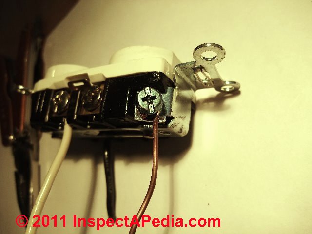
- The bare ground wire - this wire connects to the green ground screw usually found on the bottom of the electrical receptacle (photo at left). You can also see our ground wire connected at the left side of our previous photo, above-left.
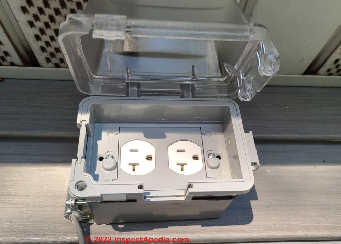
Below, a weatherproof electrical box and receptacle mounted on a home in northern Minnesota. GFCI protection for this device may be provided by a circuit breaker in the electrical panel or by a GFCI receptacle (not used in this case.)
- Nexans, THE ELECTRICIAN's HANDBOOK [PDF] Nexans Canada, 140 Allstate Parkway, Markham, Ontario Canada L3R 0Z7, TRel: 905-944-4300
Headquarters: Nexans, 4, allée de l’Arche, 92400 Courbevoie, France Phone : + 33 (0)1 78 15 00 00 Nexans Group was incorporated in 1994 but the company has a history of more than 100 years of operation.
Excerpts:
The material presented in this handbook has been extracted from the Canadian Electrical Code, Part 1, CSA Standard C22.1 – 1998, and other sources.
For authoritative reference or ruling please see the Canadian Electrical Code or consult your local inspection authority or Canadian Standards Association at (416) 747-4000.
Reader Comments, Questions & Answers About The Article Above
Below you will find questions and answers previously posted on this page at its page bottom reader comment box.
Reader Q&A - also see RECOMMENDED ARTICLES & FAQs
On 2021-08-27 by inspectapedia.com.moderator (mod) - questionable electrical work at receptacle box
 @Dave Jay,
Perhaps I'm not understanding the question; it is always permitted to correct, repair, or replace improper, damaged, worn, or sloppy electrical system components.
Depending on where you live, new work must be done by a licensed electrician.
In your photo I see what looks like un-protected wires entering the receptacle from the panel enclosure;
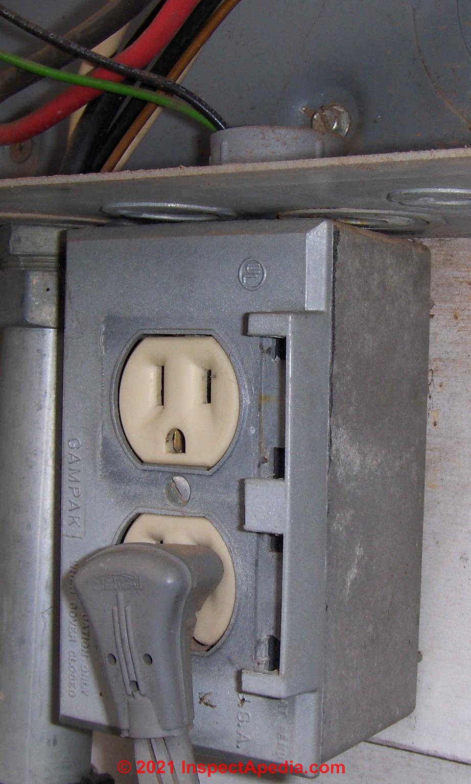
I think I also see a broken-off or missing receptacle box cover - outdoor type?
Perhaps you want an electrician to survey your building's electrical wiring and system to see just how much amateur work has been done and to assess the need for corrections; what you point out could be a tiny one-off or it might be an indicator that there is more-extensive amateur wiring in the building.
On 2021-08-26 by Dave Jay
Would like to know if possible, or permitted, to improve this pre-existing outside outlet box attached at bottom of service panel for GFCI. Appears to have been rigged with scrap parts many years ago. Thanks.
On 2020-12-18 by (mod) - watch out for more than 1 live wire in an electrical box
Will
Thank you for your comment it will be helpful to other readers. It's a good example of why it's never safe to Simply assume the power is off at an electrical box or fixture. In addition to turning off power at the breaker or fused you need to use an appropriate testing device to be sure that there are no hard wire is remaining.
The situation that you just drive also is a red flag to some electricians in building inspectors as it may indicate that a mature and incorrect electrical work has been done on the building.
On 2020-12-18 by Will
I recently built an office room in my basement and added a couple of outlet boxes that I wanted to tap into an existing ceiling box.
That ceiling box feeds a single bulb in the ceiling operated by a wall mounted switch at the doorway into the main basement room.
So I figured I would connect my new outlet "loop" to that ceiling box and use it's power for the outlets. However, when I turned off the breaker for that ceiling light I found that one breaker shut off the light but there was still power to the wires in the box supplying it.
A second breaker turned off that power. The box itself has one 14/2 coming in from the switch (I think - more later)and another 14/2 going to the light fitting, at least that's how it looks. Have I most likely missed another box somewhere that takes it's power from the second breaker ?
If so, how does one breaker turn of the actual light but another completely cuts the remaining power to the box ? When I say "I think" that 14/2 comes from the switch, it's buried in insulation, goes through studs etc, so I'm not absolutely certain.
Anyway, I hooked everything up as I said my plan was and the outlets in the new basement room are permanent live and the light in the main room is still switchable, as it was to begin with.
On 2019-02-27 - by (mod) -
Mark, please see
ELECTRICAL OUTLET HEIGHT SPECIFICATIONS
https://inspectapedia.com/electric/Electrical_Outlet_Height.php
And let me know if any questions remain and I'll be glad to pursue this further
On 2019-02-27 by Mark
Can walk plugins be 3 feet from floor
On 2018-11-08 - by (mod) -
Yes, absolutely. It's not required to daisy chain receptacles and in some areas people avoid that practice in order to improve circuit reliability.
When you daisy chain receptacles a failure in any receptacle kills everybody Downstream.
What I would do would be to use Twist on connectors in the larger box to feed the receptacle in the Box the wire going up to the new receptacle and to feed the wires going to the downstream receptacle but if you can save a pair of connectors by using the 4 terminals on the receptacle in the first box that's probably worth doing.
On 2018-11-08 by MJA
Thanks for the feedback! Yes, I full intend on increasing the box size to conform to code. I assume that the second approach I mentioned is good then.
On 2018-11-08 - by (mod) -
MJ
Physically it's simple and practical to run 14/3 wire (or on a 20A circuit 12/3) from the incoming hot wires at a nearby receptacle to the new one, using twist -on connectors if there are not enough free connector screws on the receptacle itself,.
But watch out: check the number of wires in the electrical box with the box cubic inches: you may need to use a larger box or add a sidecar to get enough space.
Watch out: if you're not trained and familiar with proper and safe electrical work you should avoid doing it - making a mistake can shock, or kill someone or burn down the house.
On 2018-11-07 by MJA
I have a 15A circuit with daisy chained receptacles on it. I'd like to add one receptacle (higher up the wall) in the middle of the circuit for a TV. There is an existing receptacle already between the two wall studs where I'd like to put the new one.
My question is: as it is daisy chained, do I need to insert this new one in the daisy chain by running one cable up and the other back down to link up with the originally downstream receptacle (in which case, providing by device box is ensured to be big enough, I assume I would simply pig tail the downstream receptacle wires to the one coming back from the new receptacle).
Otherwise, I was wondering if I could set this one receptacle wired in parallel to the existing one, in which case I'd only have to run one cable up to the new one and add some wiring and pig tails in the existing receptacle. Thanks for any info!!
Reader Question: what do I do with the screws to which no wire is connected on a conventional "plug" (wall receptacle)?
At the end of a circuit, I'm only using 2 of the 4 screws on a conventional plug. What should I do with the 2 unused screws? Should they be screwed all the way in? Or left partially unscrewed? Or does it matter? - Chris Rasko 7/8/12
Reply:
Chris:
regarding the un-used screw terminals on an electrical receptacle, you should simply screw them all the way in and leave them alone. Don't remove the screws - it's not necessary, they are deliberately hard to remove completely, and they could be needed in some future wiring change.
Reader Question: how to wire up two different circuit-powered receptacles in one electrical box
 I would like to wire 2 single plugins to one live wire..how do i do that? - Channing
Reply:
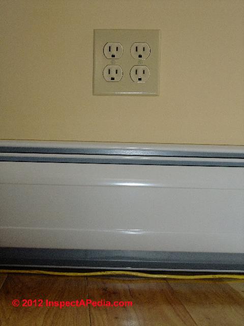
Channing, re Hooking up a Pair of Receptacles in One Electrical Box:
If your two plugins (two electrical receptacles) are located in the same electrical box (we call this a "quad" electrical receptacle installation since each individual receptacle provides connections for two wall plugs), you'll want to wire the hot and neutral to one pair of screws on the first receptacle, and use short black and white jumper wires to connect the the proper terminals on the first receptacle to the second one in the same box.
That's a perfectly acceptable use of the second pair of screw terminals you see on the receptacles.
The ground wire can be continuous, tying the two ground screws on the receptacles together and onwards to the circuit ground.
However a better practice when wiring up a quad-plex of electrical receptacles is to place left and right or upper and lower receptacles on separate electrical circuits - thus reducing the chances
There are two approaches: you can wire the left and right duplex receptacles each to different individual electrical circuits, or you can wire the upper and lower half of the pair of duplex receptacles to different electrical circuits.
Wiring a Split Receptacle to Two Different Electrical Circuits
 If you choose to wire the upper and lower duplex receptacle openings to different circuits, we call this the "split receptacle" wiring method, because we are splitting the individual duplex receptacle upper and lower connectors onto two different circuits.
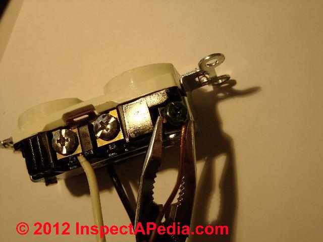
Our photo (left) shows an electrical receptacle that is being wired to a single circuit. The white neutral wire is connected to the silver screw (left side of our photo).
If we were wiring this electrical "outlet" as a split receptacle, we'd want to feed the upper and lower halves of the device from two different electrical circuits.
To do so we'd have to break away the "breakaway" connecting tab pointed to by our orange arrow.
Daisy Chaining Receptacles in Separate Electrical Boxes
If your two receptacles are in different locations and thus in different electrical boxes, your circuit that wires the second or "downstream" receptacle can be powered by those same extra terminal screws on the first or "upstream" receptacle.
You'll need to run a wire from the first receptacle through the wall into the second electrical box of course.
Wiring Electrical Receptacles on a Single Circuit In Parallel
In some jurisdictions electricians to not "daisy chain" receptacles in the same box together by using the second pair of screws on each one. Rather the circuit enters the box and using twist-on connectors, short pig-tail wires are connected to each receptacle at the proper screws.
This approach requires a larger electrical box as it will contain more connections, connectors, and so needs more room.
Because electricians often pull a multiwire circuit where they plan to split receptacle circuits within an individual electrical box while sharing a neutral wire, be sure to ake a look at multi-wire branch circuit wiring information and hook-up details
Reader Question: Which end of electrical outlets go "up"? The ground hole should be up, down, or sideways?
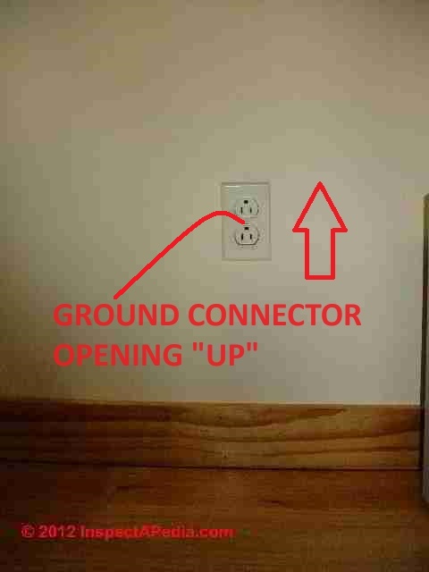
Can the outlet be installed any way? For example ground hole facing up, down, or sideways? thanks, - Anon
Reply:
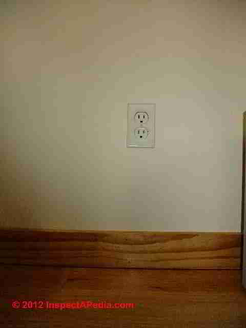
Anon, the position of installation of an electrical outlet won't affect its operation and should not normally affect its approval by the electrical inspector.
In some areas I see the outlet installed with the ground connector always "up" as in our photo at left, though to me that's less attractive than the position shown in our electrical outlet photo at far left.
I've also seen arguments expressing the OPINION that the position of the grounding pin connector might help resist the tendency of a plug to fall out of its connection.
That's nonsense. If a plug is falling out of a receptacle, one of the two objects is worn or damaged and should be replaced to assure a safe, mechanically secure connection.
Reader Question: can I connect a pigtail from multiple hot, neutral, or ground wires over to a receptacle
I have 2 receptacles that are both side and back wired, 3 hot and 3 neutral wires. I eliminated one receptacle (capping the 3 wires together) but want to keep the other.
Is it safe to just run a pigtail from the 3 wires to the receptacle? - Greg
When wiring multiple boxes in series, how do you connect both incoming and outgoing ground wires to the back of the receptacle? With 12 ga. wire, only one wire will fit under the green screw (and not very tightly, at that - there's no washer or clamp.) - Bob M.
Reply: yes but ... watch that box size
 Yes, Greg, that's a common practice. Be sure that your junction box is big enough to contain all of the wires and twist-on connectors.
Details about using pigtailing when wiring receptacles are at ELECTRICAL RECEPTACLE WIRING SERIES vs PARALLEL where we point out that you may need a larger electrical box.
Details about back-wired electrical devices (receptacles & switches) are
at BACK-WIRED ELECTRICAL DEVICES.
Bob, similar to Greg's question, I see two approaches to hooking up the ground wire in junction boxes and at electrical receptacles.
- If the incoming ground wire from the feed circuit is long enough, it can be run continuously, connected to a grounding screw that connects the wire to the metal junction box
(skip this step if plastic junction boxes are in use), on to the ground screw terminal at each electrical receptacle, and ending with a ground clamp crimp connector that ties the incoming ground to the ground wire of the outgoing wire that continues to the next junction box. - If the incoming ground wire is not long enough to run as above, then an additional length of ground wire is pigtailed to the incoming ground and makes the other connections I've described above.
In sum, all of the grounds are tied together in the box: the incoming ground, outgoing ground, and ground wires to each of the electrical receptacles.
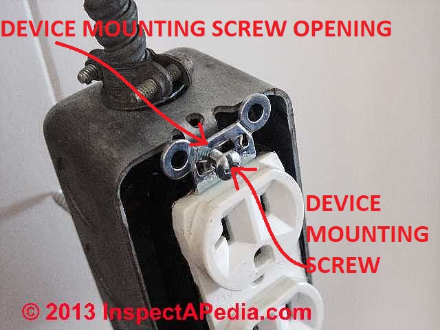
Watch out: while the electrical receptacle ground may also be electrically connected to the metal strap that mounts the receptacle to the junction box (photo at left), and while the junction box may be metal, do not rely on the receptacle mounting screws and receptacle strap-to-box contact to serve as the grounding connection.
It's easy for the receptacle mounting screws to be deliberately left loose or to work loose - making that ground connection unreliable. Use a ground wire.
Question: Can I use your wiring tips for sockets we usue in the E.U. ?
2015/10/22 Mark said:
Thank you for so detail tips. Especially pictures made me understand everything the most. I'm a memeber of EU and as you know I have another kind of sockets. Can I use your tutorials if i want to install european kind of sockets such as Obo?
OBO is een Duitse producent van systemen voor gebouwinstallatie zoals verbindings- en bevestigingssystemen, inbouwapparatuursystemen, kabel- en wandgoten, brand- en bliksembeveiliging en meer.
OBO is een familiebedrijf dat in 1911 werd opgericht als stansfabriek voor bevestigingstechniek, en wordt inmiddels geleid door de vierde generatie Bettermann.
Het bedrijf is in meer dan zestig landen actief. De vele producten van OBO worden gebruikt in bijvoorbeeld de scheepsbouw en voedingsmiddelenindustrie. Ook worden OBO-producten onder meer toegepast in zonne-energie-installaties, energiecentrales en tunnelbouw.
Reply:
Generally, yes, Mark; but take a look at the different wire colour codes used in the E.U.
See I.E.C. I.E.E. ELECTRICAL WIRING COLOUR CODE CHART at inspectapedia.com/electric/Wiring_Colours.php#IEC
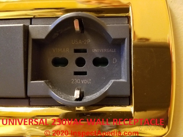
Universal 220-230-240 VAC Wall Receptacles
Note: Universal as well as 230VAC wall receptacles do not observe polarity and are wired with two 115VAC "hot" wires (giving 230VAC across the circuit) and a ground - illustrated below at an electrical receptacle in a building in Genoa, Italy.
...
Continue reading at ELECTRICAL RECEPTACLE CONNECTION DETAILS or select a topic from the closely-related articles below, or see the complete ARTICLE INDEX.
Or see ELECTRICAL OUTLET WIRING FAQs - questions & answers posted originally on this page
Or see these
Recommended Articles
- ELECTRICAL OUTLET, HOW TO ADD & WIRE - home
- 2-WIRE ELECTRICAL RECEPTACLE CONNECTIONS
- BACK-WIRED ELECTRICAL DEVICES
- ELECTRICAL BOX GROUND WIRING
- ELECTRICAL BOX RECESSED DEPTH IN WALLS
- ELECTRICAL BOX RELOCATION WIRING
- ELECTRICAL BOX FIRE SEPARATION DISTANCES
- ELECTRICAL BOX TYPES
- ELECTRICAL DUPLEX RECEPTACLE WIRING
- ELECTRICAL OUTLET ADAPTER SHORT CIRCUIT
- ELECTRICAL OUTLET HEIGHT ABOVE FLOOR
- ELECTRICAL OUTLET, HOW TO ADD in OLDER HOME
- ELECTRICAL RECEPTACLE ARC PITTING
- ELECTRICAL RECEPTACLES for 30A 240VAC CIRCUITS
- ELECTRICAL RECEPTACLE CONNECTION DETAILS
- ELECTRICAL RECEPTACLE COUNTERTOP SPACING
- ELECTRICAL RECEPTACLE COVER PLATES
- ELECTRICAL RECEPTACLE HEIGHT & CLEARANCES
- ELECTRICAL RECEPTACLE LOCATIONS
- ELECTRICAL RECEPTACLE POSITION: WHICH WAY UP
- ELECTRICAL RECEPTACLE TYPES
- ELECTRICAL RECEPTACLE WIRING SERIES vs PARALLEL
- ELECTRICAL WIRE CLEARANCE FROM DUCTS & PIPES
- GROUND WIRE CONNECTIONS
- MULTI-WIRE CIRCUITS
- NAIL STOPS to PROTECT WIRES
- NUMBER of WIRE CONDUCTORS
- OLD WORK ELECTRICAL BOXES for RETROFIT
- REVERSED POLARITY ELECTRICAL DEVICES / CIRCUITS
- ROUTING, SECURING & PROTECTING ELECTRICAL WIRES
- SIZE of WIRE REQUIRED for ELECTRICAL RECEPTACLES
- SPLICING ELECTRICAL WIRES
- STRIPPING ELECTRICAL WIRES
- ELECTRICAL WALL PLUG WIRING ID & CONNECTIONS
- LIGHT SWITCH WIRING DETAILS
- KNOB & TUBE WIRING
- SAFETY for ELECTRICAL INSPECTORS - home
Suggested citation for this web page
ELECTRICAL OUTLET, HOW TO ADD & WIRE at InspectApedia.com - online encyclopedia of building & environmental inspection, testing, diagnosis, repair, & problem prevention advice.
Or see this
INDEX to RELATED ARTICLES: ARTICLE INDEX to ELECTRICAL INSPECTION & TESTING
Or use the SEARCH BOX found below to Ask a Question or Search InspectApedia
Ask a Question or Search InspectApedia
Questions & answers or comments about how to install and wire electrical outlets or receptacles in buildings.
Try the search box just below, or if you prefer, post a question or comment in the Comments box below and we will respond promptly.
Search the InspectApedia website
Note: appearance of your Comment below may be delayed: if your comment contains an image, photograph, web link, or text that looks to the software as if it might be a web link, your posting will appear after it has been approved by a moderator. Apologies for the delay.
Only one image can be added per comment but you can post as many comments, and therefore images, as you like.
You will not receive a notification when a response to your question has been posted.
Please bookmark this page to make it easy for you to check back for our response.
Our Comment Box is provided by Countable Web Productions countable.ca
Citations & References
In addition to any citations in the article above, a full list is available on request.
- Timothy Hemm has provided photographs of various electrical defects used at the InspectAPedia TM Website. Mr. Hemm is a professional electrical inspector in Yucala, CA.
- Mark Cramer Inspection Services Mark Cramer, Tampa Florida, Mr. Cramer is a past president of ASHI, the American Society of Home Inspectors and is a Florida home inspector and home inspection educator. Mr. Cramer serves on the ASHI Home Inspection Standards. Contact Mark Cramer at: 727-595-4211 mark@BestTampaInspector.com
- John Cranor [Website: /www.house-whisperer.com ] is an ASHI member and a home inspector (The House Whisperer) is located in Glen Allen, VA 23060. He is also a contributor to InspectApedia.com in several technical areas such as plumbing and appliances (dryer vents). Contact Mr. Cranor at 804-873-8534 or by Email: johncranor@verizon.net
- [3] NFPA - the National Fire Protection Association can be found online at www.nfpa.org
- [4] The NEC National Electrical Code (ISBN 978-0877657903) - NFPA might provide Online Access but you'll need to sign in as a professional or as a visitor)
- US NEC Free Access: See up.codes at this link: https://up.codes/code/nfpa-70-national-electrical-code-2020
- [5] Special thanks to our reader Steve who pointed out prior errors in our illustrations.
- [6] Simpson Strong-Tie, "Code Compliant Repair and Protection Guide for the Installation of Utilities in Wood Frame Construction", web search 5/21/12, original source strongtie.com/ftp/fliers/F-REPRPROTECT09.pdf, [copy on file as /Structures/Framing/Simpson_Framing_Protectors.pdf ]. "The information in this guide is a summary of requirements from the 2003, 2006 and 2009 International Residential Code (IRC), International Building Code (IBC), International Plumbing Code (IPC), International Mechanical Code (IMC), 2006 Uniform Plumbing Code (UPC) and the 2005 National Electrical Code."
- "Electrical System Inspection Basics," Richard C. Wolcott, ASHI 8th Annual Education Conference, Boston 1985.
- "Simplified Electrical Wiring," Sears, Roebuck and Co., 15705 (F5428) Rev. 4-77 1977 [Lots of sketches of older-type service panels.]
- "How to plan and install electric wiring for homes, farms, garages, shops," Montgomery Ward Co., 83-850.
- "Simplified Electrical Wiring," Sears, Roebuck and Co., 15705 (F5428) Rev. 4-77 1977 [Lots of sketches of older-type service panels.]
- "Home Wiring Inspection," Roswell W. Ard, Rodale's New Shelter, July/August, 1985 p. 35-40.
- "Evaluating Wiring in Older Minnesota Homes," Agricultural Extension Service, University of Minnesota, St. Paul, Minnesota 55108.
- "Electrical Systems," A Training Manual for Home Inspectors, Alfred L. Alk, American Society of Home Inspectors (ASHI), 1987, available from ASHI. [DF NOTE: I do NOT recommend this obsolete publication, though it was cited in the original Journal article as it contains unsafe inaccuracies]
- "Basic Housing Inspection," US DHEW, S352.75 U48, p.144, out of print, but is available in most state libraries.
- In addition to citations & references found in this article, see the research citations given at the end of the related articles found at our suggested
CONTINUE READING or RECOMMENDED ARTICLES.
- Carson, Dunlop & Associates Ltd., 120 Carlton Street Suite 407, Toronto ON M5A 4K2. Tel: (416) 964-9415 1-800-268-7070 Email: info@carsondunlop.com. Alan Carson is a past president of ASHI, the American Society of Home Inspectors.
Thanks to Alan Carson and Bob Dunlop, for permission for InspectAPedia to use text excerpts from The HOME REFERENCE BOOK - the Encyclopedia of Homes and to use illustrations from The ILLUSTRATED HOME .
Carson Dunlop Associates provides extensive home inspection education and report writing material. In gratitude we provide links to tsome Carson Dunlop Associates products and services.
 | HOME | ABOUT | ASK a QUESTION | CONTACT | CONTENT USE POLICY | DESCRIPTION | POLICIES | PRIVACY | |
| © 2024 - 1985 Publisher InspectApedia.com - Daniel Friedman | |||||||||