
InspectAPedia® FREE Encyclopedia of Building & Environmental Construction, Diagnosis, Maintenance & Repair |
Question? Just ask us! InspectAPedia
|
 Knob & Tube Electrical Wiring Safety
Inspection, Evaluation, & Repair Suggestions
- POST a QUESTION or COMMENT about knob and tube wiring: inspection, detection, & repair advice
Guide to knob and tube electrical wiring:
This article answers basic questions about Knob and Tube electrical wiring. We define knob and tube wiring, we include photographs that aid in recognition of this generation of electrical wiring, and we describe both proper and improper K&T wiring installations, repairs, or circuit extensions.
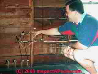
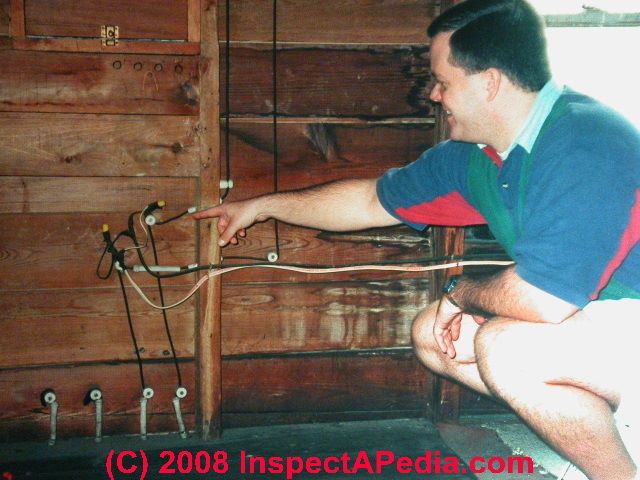
This website provides information about a variety of electrical hazards in buildings, with articles focused on the inspection, detection, and reporting of electrical hazards and on proper electrical repair methods for unsafe electrical conditions. Our page top photo shows a home inspection client pointing out knob and tube electrical wiring in an older home.
InspectAPedia tolerates no conflicts of interest. We have no relationship with advertisers, products, or services discussed at this website.
Knob-and-tube wiring in older homes: description, inspection, repair
 Knob and tube electrical of wiring has been installed in homes from the 1920s right up into the 1970's in some jurisdictions.
These photos above will assist homeowners and inspectors in recognizing the knob & tube electrical wiring method as well as common safety defects for which an inspector should be alert.
The photo shows knob and tube electrical wires passing through a wall top plate in a 1920 New York home.
[Click to enlarge any image]
Article Contents
- KNOB & TUBE WIRING PROPERTIES
- KNOB & TUBE WIRING ILLUSTRATIONS
- DAMAGED KNOB & TUBE WIRING
- EFFECTS of INSULATION on KNOB & TUBE CIRCUIT SAFETY
- KNOB & TUBE WIRING EXTENSIONS ELECRICAL CODE CONCERNS
- ADVICE on IMPROVING KNOB & TUBE WIRING SAFETY
Characteristics & Safety Considerations of a knob and tube electrical circuit
- No ground:
Only a hot and neutral wire are provided.
Watch out: A knob and tube electrical circuit has no electrical ground path. - Wire insulation:
The individual electrical wires are wrapped in a rubberized cloth. That was fine when the wires remained suspended in air and had not been chewed by a squirrel.
Look for wires that have been overheated such that the insulation is dry and cracked or crumbling. - Knob and tube wiring connections or splices
were made outside of electrical junction boxes. In normal practice knob and tube wiring splices are soldered and also taped.
We describe these splices at "Taps"
in ELECTRICAL SPLICES, HOW TO MAKE.
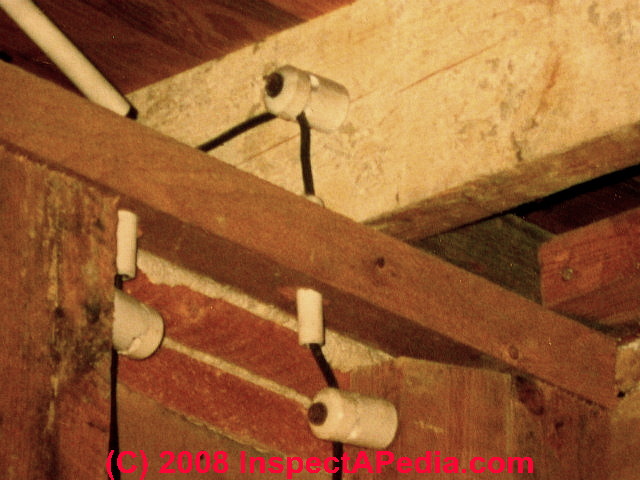
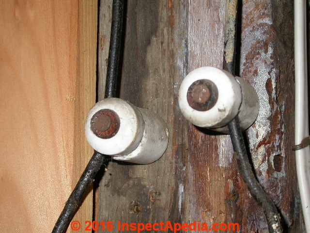
- Ceramic tubes (shown above) route knob and tube electrical wires through building framing members:
Wherever the knob and tube circuit wires pass through building framing lumber a ceramic tube is used to insulate the wire from the wood.
These thick ceramic tubes are a good insulator separating electrical wire from wood - if both are un-damaged. Our photos just above and just below show knob and tube electrical wiring in the Justin Morrill Smith historic home in Strafford VT.

- Ceramic knobs (shown above) support knob and tube electrical wires passing over building framing surfaces:
Where the knob and tube wiring is surface mounted in a building it is attached using a ceramic "knob".
These ceramic knobs are a good insulator provided they have not been damaged or modified.
Our photo above at left shows knob and tube electrical wiring in the Justin Morrill Smith historic home in Strafford VT. Also see ceramic tubes supporting knob and tube circuits in other photos and sketches on this page.
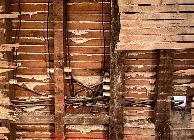
Our photo above, adapted from reader Lucas' photo of K&T wire, illustrates previously-concealed knob and tube electrical wiring, now exposed as the wall has been opened.
- Concealed knob and tube wiring:
for example where knob and tube wiring was run inside of building wall or ceiling cavities, its condition is unknown and it might be unsafe.
Examples of events reducing the safety of knob and tube wiring and increasing the risk of an electrical fire include
insulation may have been added to the building cavity: the wiring is no longer suspended in open air and is at greater risk of overheating.
rodents may have gnawed or damaged the knob and tube wire insulation leaving exposed conductors
Even in jurisdictions where K&T wiring remained "legal" up to recent years , concealed knob and tube wiring may be prohibited or, as seen in New York City's 2011 electrical code technical provisions, the installation of concealed knob and tube wiring is not permitted.
NEW YORK CITY 2011 ELECTRICAL CODE TECHNICAL PROVISIONS: ARTICLE 394, CONCEALED KNOB-AND-TUBE WIRING [PDF] (2011) - retrieved 2023/05/06, original source: nyc.gov/html/dob/downloads/bldgs_code/electrical_code_local_law_39of2011.pdf
Illustrations of Proper and Improper Knob and Tube Wiring Details

The sketch above, courtesy of Carson Dunlop Associates, shows the usual ways that knob and tube electrical wiring is connected in homes. Below: knob and tube electrical wiring, including the ceramic components, fasteners, and the electrical conductors themselves may look as if they're in great shape.
That's what I think of the K&T photo just below. But beware: the electrical wiring you see at first glance may be in terrible condition somewhere else in the building. Here are some things you need to know about knob and tube electrical wiring.
-
Knob and tube electrical circuits are not "illegal"
and there is not a code requirement that they be replaced. However this wiring method is considered obsolete. - No electrical ground is provided
the circuit is less safe than a modern grounded electrical circuit. Appliances and devices that use a grounded plug should not be connected on an un-grounded circuit. - The knob and tube wiring may have become damaged
by age, exposure to leaks, or to chewing rodents. In attics, for example, we often see that this wiring has been damaged by having been stepped-on or by chewing rodents. - The safety of the knob and tube circuit may have been affected by building changes
such as adding insulation (discussed next) and modifications to the original circuit (discussed below).
Damaged Knob & Tube Electrical Wiring
As with any older electrical wiring but particularly where wiring is exposed such as in an attic floor, the wiring may have been mechanically damaged by foot traffic, building leaks, building movement (earthquakes for example) or by inattentive electrical or other contracting work.
Beyond the obvious snafus like broken wires or broken, lost ceramic knob and tube supports and insulation, look more carefully at wiring for cracking or damaged insulation.
Look also at the wiring support wherever there is visual access to do so. That may tell you to be more or less worried about the wiring sections that you cannot see.

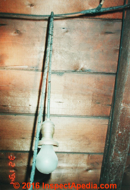
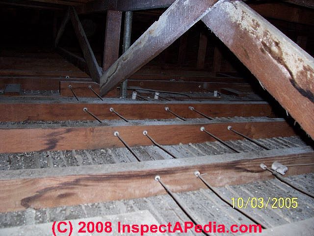
Above: running this old electrical conductor over a nail to "hang" an attic light fixture is likely to damage the conductor over time - it is unsafe.
Look to the right of the "light pendant" at the plugs and sockets used to connect additional knob and tube circuits running along the roof: someone who's not an electrician has been at work here, raising a red flag suggesting more thorough inspection of the electrical wiring.
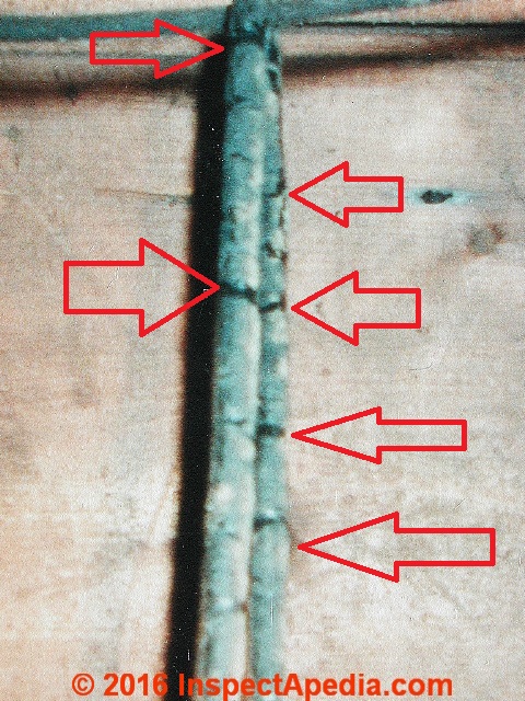
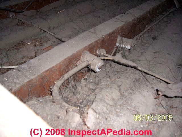
Below some had a similar attic lighting idea but worse: the light is suspended by hanging it from a knob and tube wire itself.
The second knob and tube wiring damage photograph below shows some of the cracks in the light wire insulation.
But more, knob and tube conductors are not intended to be used to hang the laundry, towels, nor other light fixtures.
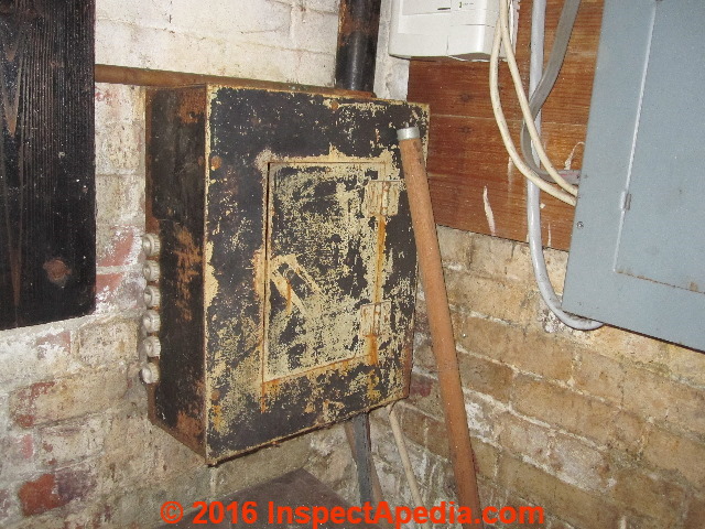
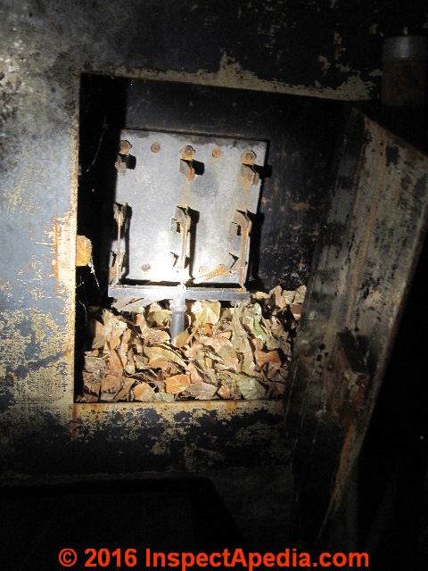
Below: the original electrical fuse panel that powered a knob and tube wired Poughkeepsie, New York home is shown before and after we opened its panel door to have a look inside.
and now the mouse hotel:
When should K&T Wiring be Replaced?
OPINION:
K&T wire probably should be replaced if easily accessible such as in an attic or basement, or if the walls or ceilings are opened for other reasons.
It is highly recommended and K&T wire should be replaced if:
- if any of the circuits are erratic or intermittent.
- if the K&T wires or joints were every over heated,
- if the K&T wires ever stepped on or otherwise impacted or damaged,
- if the K&T rubberized fabric covering is brittle and fractured with age,
- if the K&T wire was ever submerged or extensively soaked
- if the K&T wire is going to be surrounded by insulation. Any insulation completely changes the fire rating and safety of the K&T wiring.
Ignoring these recommendations is not [a violation of the national electrical code], nor is it illegal, but is risky, unsafe, and potentially dangerous.
K&T (knob and tube) wiring has several major inherent disadvantages compared to modern wiring.
First, it has no third wire ground conductor to protect the user in case of an internal fault within an appliance that a user may plug into a receptacle.
Second, the wires and receptacles are not polarized. This means that the larger shell of an incandescent lamp or the chassis of a hifi system or computer could be at the 120 volts potential of the hot wire instead of the near zero volts of the neutral conductor.
Both of these conditions could lead to a user being shocked or electrocuted which would not happen with normal more modern polarized and grounded electrical system.
With age, the rubberized cloth insulation on K&T may decay with mold, may dry out and fracture, and sometimes even falls off, potentially exposing people to hot electrified wires.
Old K&T is legal in the sense that it has been grandfathered in. Codes do not mandate retroactive replacement. However, it is absolutely not permitted or legal to install [new knob and tube circuits] today, and in many or most locations, it cannot be extended or modified.
K&T wiring is probably okay if
- If the K&T wire is fully contained within a wall or joist cavity where it is fully protected from being stepped on, being accidentally pulled or displaced, or otherwise damaged,
- if the K&T wire insulation is still intact,
- if the K&T wire has not been overheated.
- [if the K&T wiring has not been subjected to flooding or soaking ] -
See details at WET SUBMERGED K&T WIRING
- Ozzie, by private email 2017/03/31
Effect of Building Insulation on Knob and Tube Electrical Circuit Safety
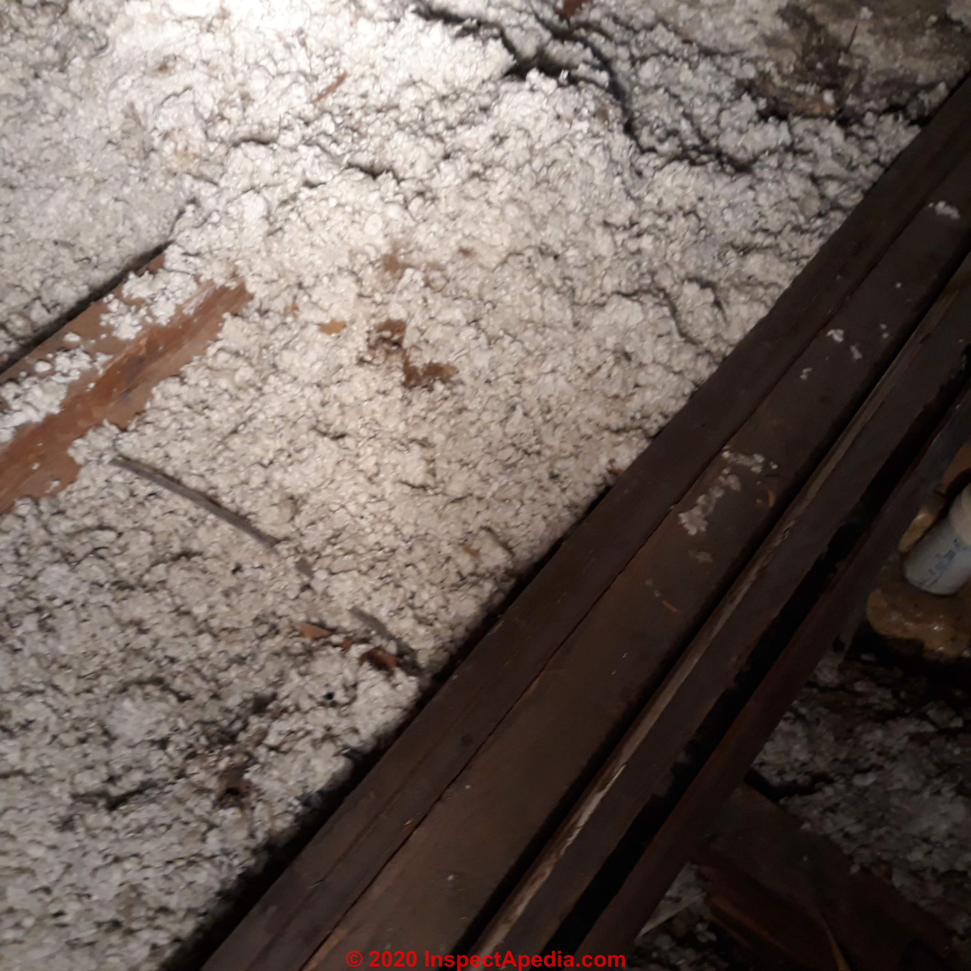
Adding building Insulation changes the knob and tube wire game: The fire safety of knob and tube wiring relied on the fact that the wires were generally routed through the air, suspended by knobs and protected by a heavy ceramic tube where passing through wood.
The two photos above, courtesy of Tim Hemm, show a knob and tube circuit that has not been covered with insulation (though we wonder about the significance of those leak stains on the ceiling joist forming the attic floor), while the knob and tube circuit in the right photo has been partly buried in blown-in cellulose insulation.
We pose that the same insulation project may have filled wall cavities with insulation too, possibly leading to overheating of knob and tube circuits that run in the building's exterior walls. We're also concerned that where knob and tube wires have been run in an attic floor and later covered
by insulation, there's a good chance that someone walking in the attic has stepped-on and damaged the wires - a condition we've found often.
The contractor who blew cellulose loose-fill into the attic shown above he wanted to make the home warmer. You can see that covering the knob and tube electrical wiring makes it easy to step on it while clambering around in a dim attic:
damaging the wiring, causing a fire, an event that will certainly warm the home. Consider also what two-word expletive you'll grunt while falling through the ceiling after you trip over a "hidden" electrical wire.
Where knob and tube electrical wires were routed in walls or in attic floors, and where later those building cavities have been insulated, the knob and tube wires are no longer suspended in air, can become hotter than intended, and may be a fire hazard for that reason.
Question: my knob and tube wiring is buried in insulation
 ...
... 
Re-posting from private email:
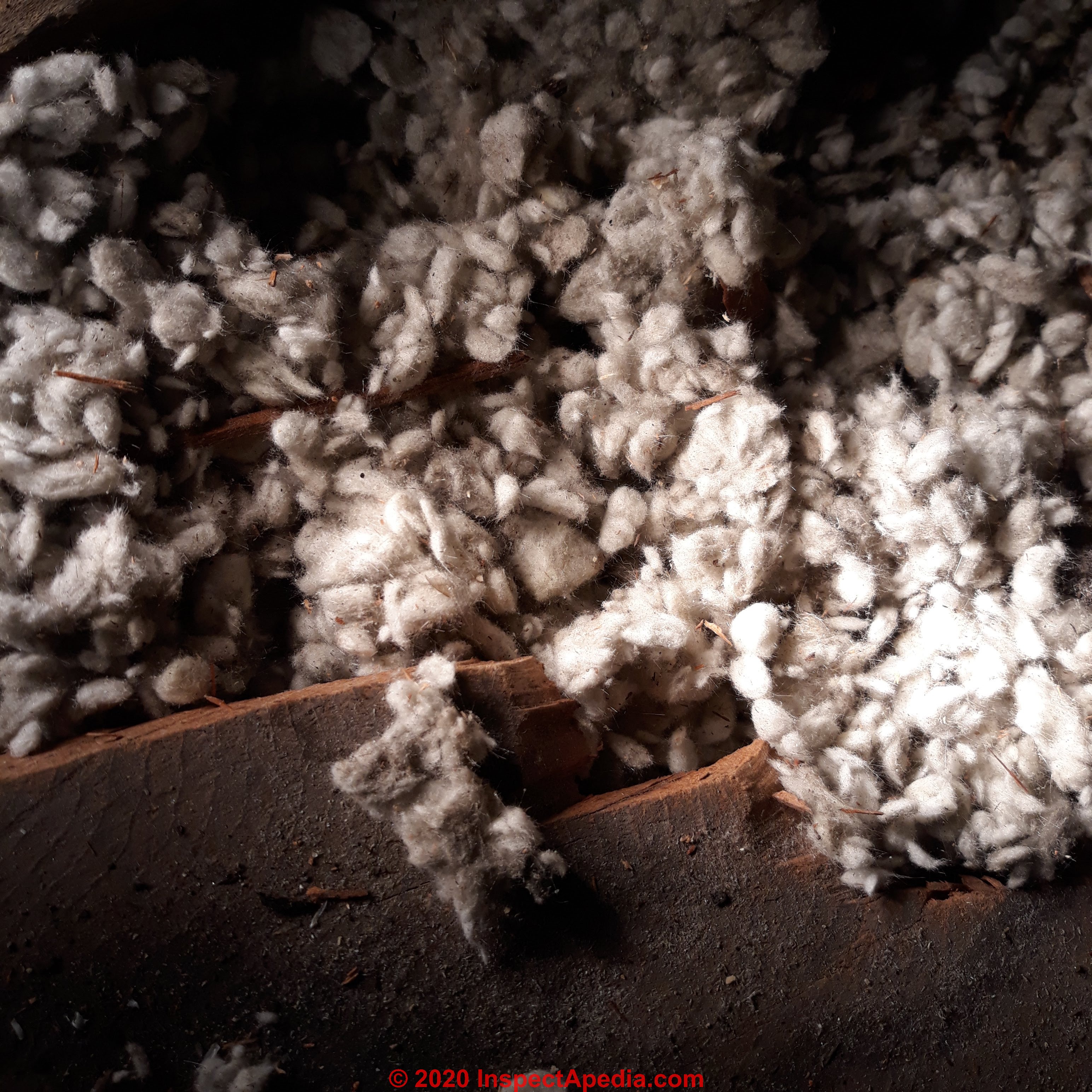
[I] thought I put picture and question in comment but don't see a response.
I am trying to identify this type of insulation- looks like a rope that is spun.
- Anonymous by private email 2020/10/12
Moderator reply:
Sorry for the confusion ..., photos and comments containing them don't appear until approved by the moderator.
If you remember the page where you left a question I'll be sure that it's made visible.
Your photos look like mineral wool insulation.
Reader follow-up: I was told there can't be insulation in floor because your not suppose to be next to knob and tube. Mine is buried in the insulation.
Thank you for the clarification. I am do thankful for the site. The house built it 1904, has knob and tube. Was told there can't be insulation in floor because your not suppose to be next to knob and tube. Mine is buried in the insulation. Looks like it has been there a long time.
Moderator reply:
Whoever told you about not insulating around K&T was, more or less, correct. That knob and tube wiring, quite safe in its original concept, expected to be suspended in air in building cavities; when you insulate it you raise its potential temperature and could make the wiring unsafe.
However adding insulation was very common and zillions of homes were so-modified.
If you're not going to face the cost of re-wiring, at the very least, be sure that none of the circuits is over-fused, and take care to keep the load on those circuits to a minimum - no electric heaters for example;
See details at:
KNOB & TUBE WIRING inspectapedia.com/electric/Knob_and_Tube_Wiring.php
Safety & Electrical Code Concerns with Knob and Tube Electrical Circuits that Have been Extended or Spliced-into or otherwise modified or disturbed
Model electrical codes do not prohibit the presence or use of knob and tube wiring circuits in buildings, but you will want to be sure that the specific knob and tube wired circuits in your building are in good condition, safe to use, and that the circuit has not been improperly modified.
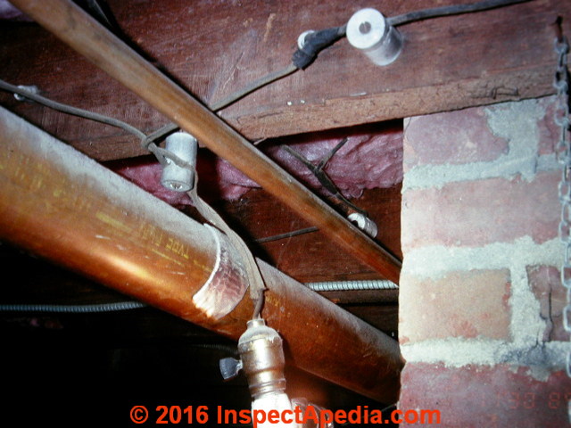
Below is a photo of knob and tube wiring supporting a light fixture - well not exactly. If readers are not sure why this wiring makes me nervous use the page top or bottom CONTACT link to tell me what you think about running an old brittle light wire conductor over copper plumbing pipes.
Extensions to knob and tube electrical wiring:
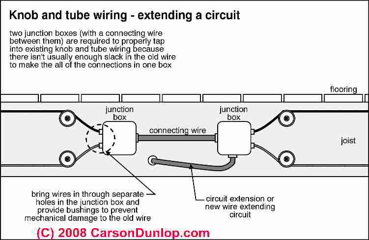
Often the original knob and tube wired electrical circuit has been modified or extended by subsequent building owners/occupants - an improper practice that is may not be permitted depending on codes that apply where the building is located. Carson Dunlop's sketch, above illustrates how knob and tube circuits are often extended.
Image provided courtesy of Carson Dunlop Associates, a Toronto home inspection & education company.
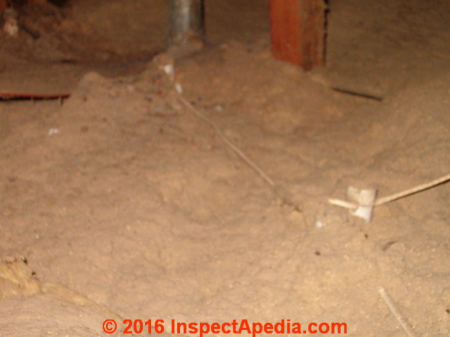
Our photo at the top of this page shows an inspection client pointing to a modern plastic NM electrical cable that has been used to extend an older knob and tube electrical circuit.
In some jurisdictions, extending an existing knob and tube circuit is not recommended, and is even an illegal installation: by adding load to the knob and tube circuit, risks increasing the temperature of the wiring and possibly causing a fire.
Watch out: for improperly abandoned knob and tube electrical wiring, knob and tube circuits that have been extended to include new circuits and devices, damaged knob and tube wire and wire insulation, knob and tube wire that has been insulated-over or around, changing its heat rating and perhaps creating a fire risk, and other K&T damage or defects that make the wiring system unsafe.
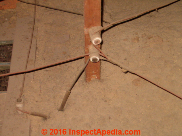
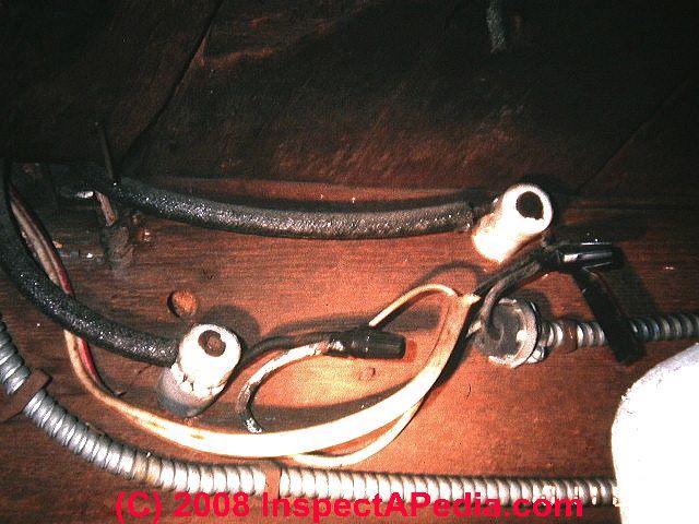
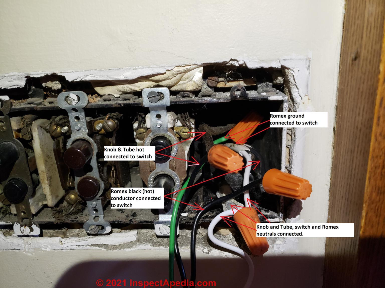
Our photos below show a combination of errors, extending a knob and tube electrical circuit and a twist on connector electrical splice outside of an electrical junction box. Immediately below is a DIY extension of an existing knob and tube electrical circuit.
Extending an existing K&T circuit to add more circuits, wires, devices, switches, lights, receptacles is not permitted. The concern is that you're going to overload an old electrical conductor, causing overheating and a fire: a risk that is increased if the wiring has been insulated-over or has been gnawed bare by rodents.
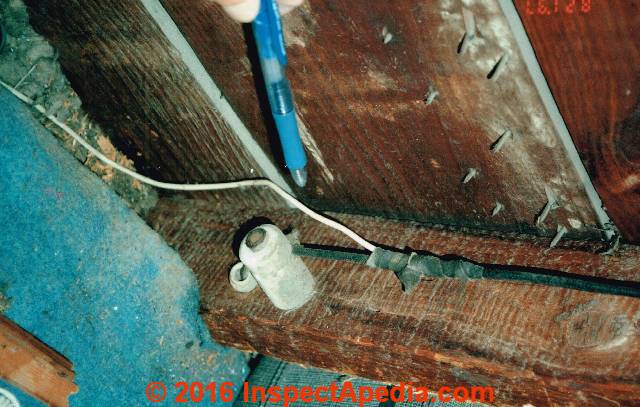
Below: this knob and tube circuit has been extended by running it into an electrical box.

Above and below: the knob and tube wiring circuit has been run to an electrical box where it is used to extend to additional circuits in the building.
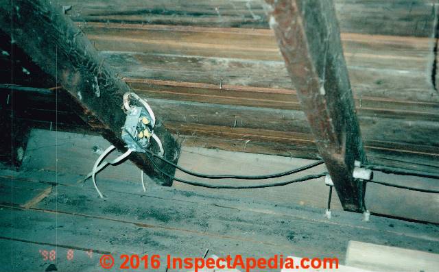
Then there's more: the DIY wiring, missing box cover, overcrowded electrical box, unprotected knob and tube conductor run through the electrical box opening, damaged wiring conductors, exposed bare wires at splices, possible evidence of wire overheating, and more. [Click to enlarge any image]
The photo below also shows three types of electrical circuit wiring: knob-and-tube, armored "BX" cable, and plastic cable wires. The photo shows therefore three generations of electrical wiring (and probably other modifications) in this building.
Below: take a close look at this photograph and note the blackening of an old sill plate and ceramic knob. I think this electrical circuit may have been exposed to fire. If so the wire itself is likely to have suffered damage and may thus be unsafe.

Advice about improving the safety and reliability of knob and tube electrical wiring

[Click to enlarge any image]
Above: new knob and tube electrical wiring applied to a lighting circuit in Japan.
- Inspect the whole electrical system: An expert should inspect the condition of the building electrical wiring, including the wires, connections, devices like receptacles, switches, and overcurrent protection by fuses or circuit breakers.
- Replace bad circuits: Knob and tube circuits that have been modified, damaged, or covered with insulation should be replaced with a modern grounded electrical circuit.
- Ground fault protection GFCI CIRCUIT PROTECTION
and possibly ARC FAULT CIRCUIT PROTECTION can be added on two-wire un-grounded electrical circuits to reduce the chances of electrical shock or fire - steps that we recommend.
See details at AFCIs ARC FAULT CIRCUIT INTERRUPTERS.
(A homeowner cannot safely test a GFCI while it is in place, installed on an electrical circuit that has no ground but the GFCI can still be expected to work correctly if it is wired properly.)
Reader Comments, Questions & Answers About The Article Above
Below you will find questions and answers previously posted on this page at its page bottom reader comment box.
Reader Q&A - also see RECOMMENDED ARTICLES & FAQs
On 2023-05-17 by Robert - Code Check Electrical book answers knob and tube question
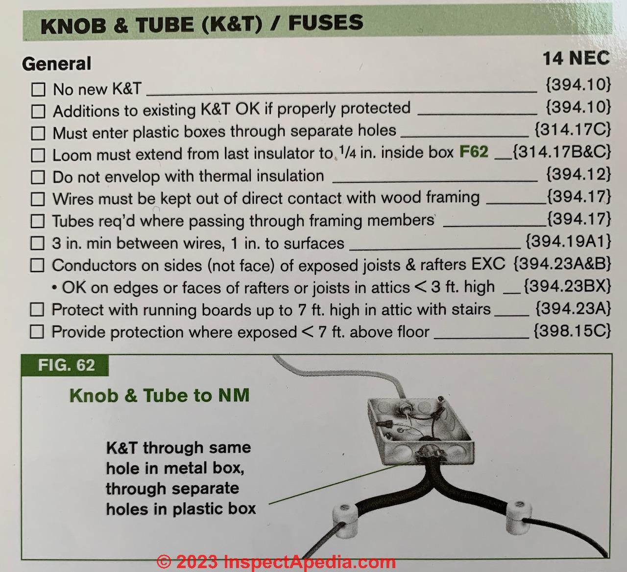
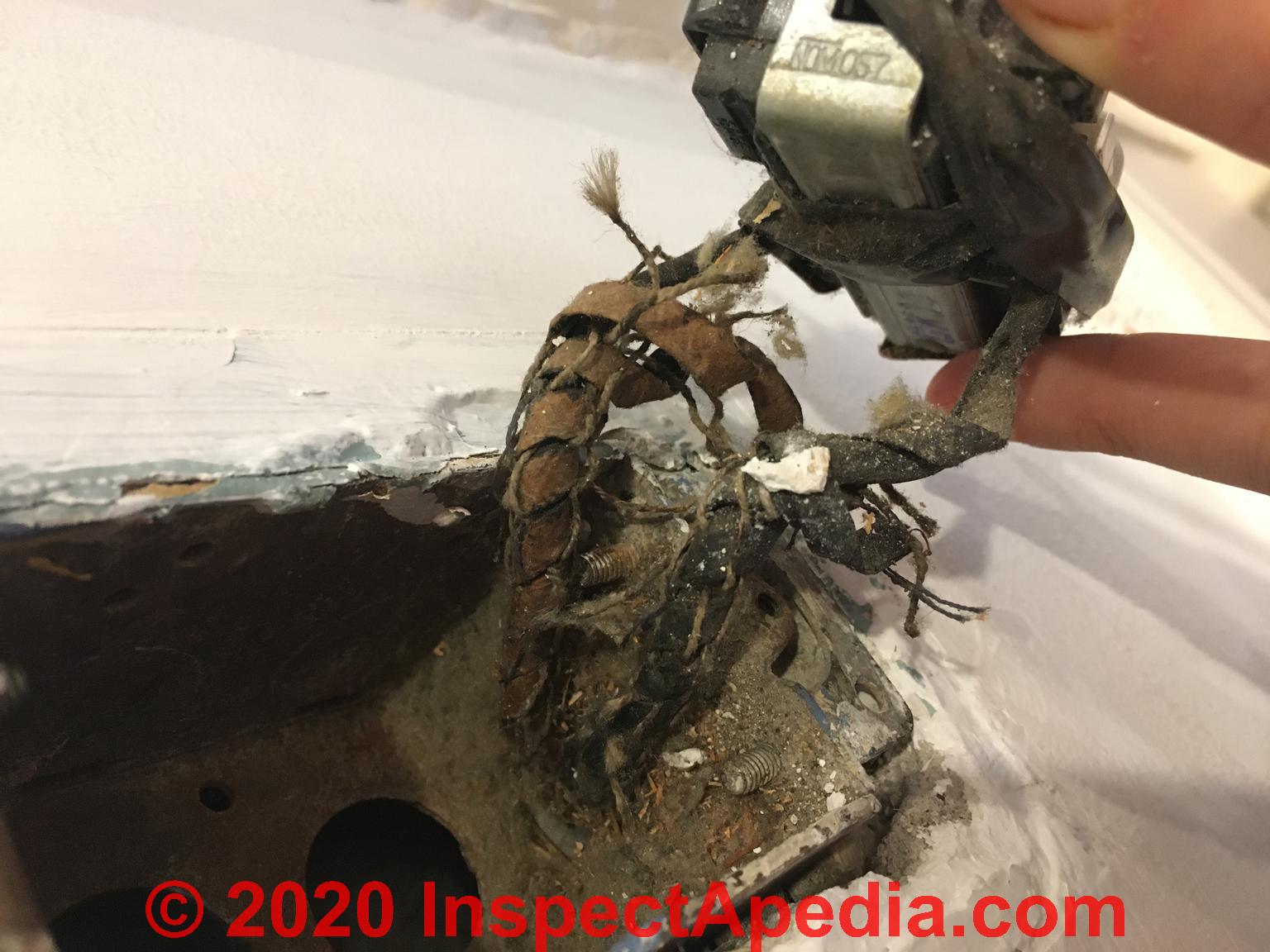
@InspectApedia DF, First off, thank you for all your info. On a side note, I personally wanted to avoid the plastic button clamps: These are very, very tight and difficult to pull wire through...fine for romex, but (to me), too much stress on knob & tube insulation.
But...I'm a dumb-butt: I have a copy of the Code Check Electrical book, and didn't realize it actually had a section devoted to this exact question. As you can see...both wires enter through one knockout in a metal box (using standard romex-style clamps), but separate holes in plastic boxes. So...mystery solved, thank you so much again for all your time and help.
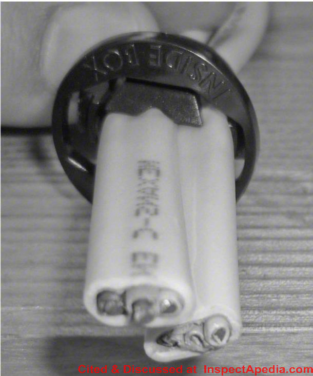
On 2023-05-16 by InspectApedia DF (mod) - plastic wiring knockout wiring opening protector
@Robert,
for other readers, here's an example of the plastic wiring knockout wiring opening protector mentioned by Robert. Like the antique ceramic knob and tube connectors, it only passes the electrical wire through an opening; it doesn't grasp it.
But as you can see, the designers also think you're passing NMC wire not antique, less-insulated knob and tube wire.
On 2023-05-16 by InspectApedia DF (mod)
@Robert,
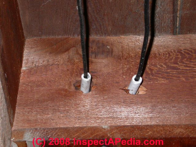
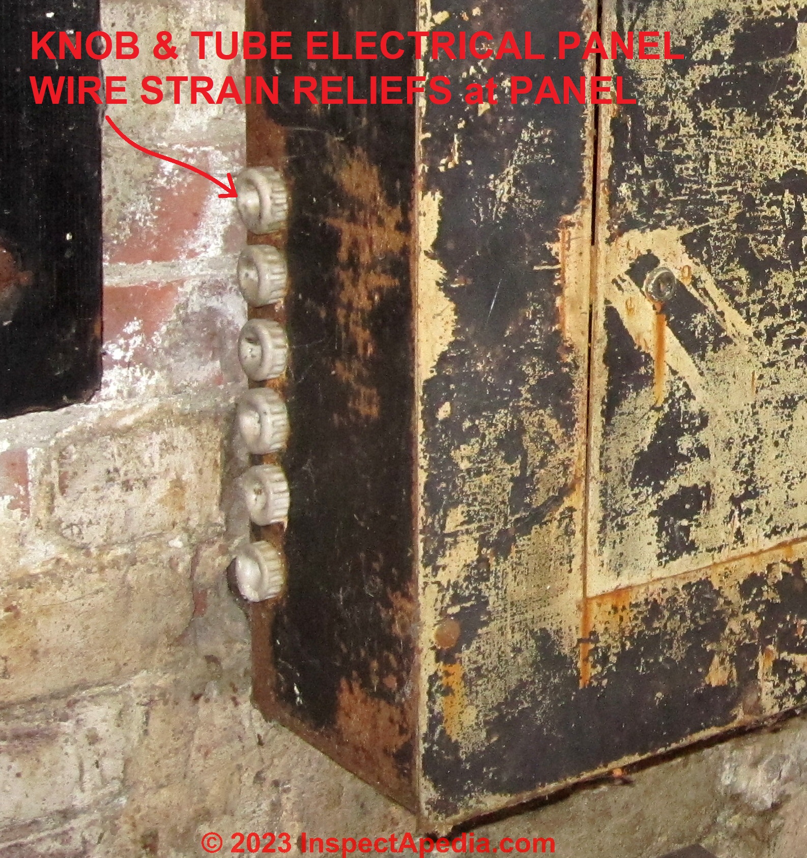
OK so I found what I was looking for: in original installation, where knob and tube electrical wiring entered/exited from the electrical panel, round ceramic strain reliefs were employed, such as those shown in my photo taken in a Poughkeepsie New York home a decade or so ago.,
This knob and tube electrical panel was no longer in use, so you won't see any wires, just the steel panel enclosure and ceramic strain reliefs.
These ceramic knob and tube strain reliefs were manufactured in two parts that simply screwed together through the electrical panel knock-out opening - a make and female half. Thus we have a smooth ceramic - lined opening through which one or two knob and tube wires passed into and out of the electrical box itself.
Similar strain reliefs would have been used at an electrical junction box for knob and tube, though those were more rare as more-often splices were in open air, wrapped with friction tape.
At a modern installation I suspect that we'll have trouble finding a strain relief that is problem-free and completely compliant with modern electrical codes.
A steel clamp type strain relief will pinch the wires in a way never intended in original knob and tube wiring design. The wire insulation may be too thin and fragile to pinch safely.
2. The Raco NMSC plastic strain relief is closer to the original ceramic ones in concept but is designed to pass modern electrical wiring that has more-durable insulation in more layers.
3. I'm sure you'll agree that we would not just pass K&T wires through an unprotected knockout opening - risking abrasion, wire damage, a short circuit.
4. I'm concerned that a technically attentive electrical inspector could not even approve (except as "grandfathered") an open ceramic strain relief originally intended for knob and tube wiring when added to a modern electrical panel because the ceramic knob and tube wire strain relief does not close off openings completely enough to protect against the escape of sparks.
4. Wrapping the K&T wire with friction tape where it passes through a steel BX connector without its clamp, or a Raco plastic connector might be what one of the old timers would have done.
5. The electromagnetic field itself isn't a concern any more that it is in modern NMC electrical wiring that places the hot and neutral and ground just mm apart. But the insulation properties are a concern. K&T wiring insulation presumed that wires ran in open air to allow heat dissipation.
Bottom line: you're probably on your own, making a best judgment. I would be very grateful if you'd ask your local electrical inspector what she or he will accept for this knob and tube wire-to-panel strain relief installation.
On 2023-05-15 by InspectApedia Publisher - what type of clamps/connectors are recommended for when K&T wires need to enter into a modern metal box?
@Robert,
Nice question.
We'll do some research before lapsing into mere opinion.
On 2023-05-15 by Robert
Hi, I wanted to ask what type of clamps/connectors you recommend for when K&T wires need to enter into a modern metal box? My initial thought was the NMSC connectors on Raco boxes would be preferable as they provide 2 separate small knockouts (i.e., the wires would remain separated), but I've seen info that this would need to a “slot” cut between them to keep magnetic fields from surround the two conductors.
Would having the two wires go through 1 single connector be preferable? And/or would plastic connectors be better than metal?
Thanks so much
On 2023-04-16 by InspectApedia Editor - You can not, in my opinion, identify original knob and tube circuits that have been extended or "spliced onto" by electrical tests of any sort
@jackofallthumbs,
You can not, in my opinion, identify original knob and tube circuits that have been extended or "spliced onto" by electrical tests of any sort,
but you can inspect the most-likely areas where such splices occur. I'll list those that occur to me.
1. Look in the basement or crawl space for knob and tube circuits and follow the wiring; Look for newer BX (armored cable) or Romex or plastic or NMC cable as well and follow it to its termination - by eye.
2. Look in the attic with the same object in mind as in step 1
3. In finished areas of the home, look at electrical receptacles to see if you are finding a mix of older two-prong with no ground - type receptacles and newer electrical receptacles that sport a ground plug opening.
In a K&T wired home I am suspicious that
- grounded electrical receptacles may have been installed as a repair or an "update" simply by replacing older un-grounded models, but in fact there may be no ground present.
That's not an immediate disaster, but I want to be double sure that no one installed a bootleg ground such as to a nearby water pipe or to metallic-sheathed wire - using those as a ground path is unsafe;
4. Since you are seeing NO knob and tube runs connected right into the main electrical panel, follow the wires again, looking for a sub panel or even one or more larger junction boxes that feed knob and tube circuits from wires in the main panel.
5. For high-risk areas, you can install GFCI or AFCI or both types of electrical receptacles (kitchen, bathrooms, garage, basement) to reduce the shock hazard. Those devices can work to reduce risk even where no ground is present, though they can't be tested using their built-in test buttons (as those rely on a local ground).
6. I'm concerned about changes to the K&T wire that increase the risk of a fire, such as
- rodents chewing off insulation from the wiring
- addition of blown-in insulation in wall or ceiling spaces where K&T was run - changing the heat properties of the wire that was intended to be suspended in open air
If you find a K&T circuit that's obviously damaged, safest is to shut it off entirely, pending re-wiring.
Post some photos (one per comment) of what you're finding and we can comment further. - DF
On 2023-04-16 by jackofallthumbs
Kind of an emergency question. I’m 500 miles from home, assisting my 70 year-old brother, who’s now quite immobile. His house is 100 years old, and four stories tall, and features a hodgepodge of wiring, including ACTIVE knob and tube.
He has all the risk factors in your very helpful article: past rodent activity, blown in cellulose insulation, past water damage, and extensive use of resistance heaters in multiple rooms.
My question is: assuming that some original K&T circuits have been spliced into, how do I identify which circuits those are, given that the splicing can have been made at either end? For example, there are no K&T runs that enter the updated panel.
On 2022-04-13 by Inspectapedia Com Moderator - How to repair break in knob and tube wire in attic?
@Mad Monty,
Thank you for your kind comment - we work hard on this material so we're really grateful when readers notice what we're up-to.
About that K&T wiring, as you probably know, current electrical codes permit K&T to remain in use (*provided it's un-damaged) but it's not supposed to be extended.
That puts us in a tricky spot when a case like yours comes-up: the K&T circuit needs to be interrupted and re-routed around something else being installed.
While original knob and tube splices were often left exposed, wrapped in cloth friction tape, for a modification such as you describe, I would put the splices in a modern electrical junction box and use approved twist-on connectors. Then cap off the boxes with simple blind cover.
On 2022-04-12 by Mad Monty
How to repair break in knob and tube wire in attic? Discovered that the installer of a whole house attic fan had cut and spliced unrelated live knob and tube wires to reroute them around the fan. The K&T wires were simply wire nutted to single conductor THHN at each end, no junction boxes used.
We suggest removing the spliced section, installing a plastic junction box at each end, and replacing the THHN with Romex. Bring each K&T wire into its JB through the built-in plastic pinch connector, wire nut it to the Romex. Route and fasten the Romex per code.
Is this the best way to do it? Thanks for taking questions and taking the time to run an independent free advice site. I'll keep your site bookmarked and your advertisers in mind.
On 2022-01-21 by Inspectapedia Com Moderator - Changing out manual switch for a Kasa HS200 smart switch with knob and tube wiring - SNAFU
@Ken,
Please do keep us posted as what you eventually find out as the cause of this light switch problem will certainly help other readers as well.
The conversation demonstrates the difficulty of troubleshooting building problems based solely on text and self-reporting.
In over 50 years of building diagnosis I have found that virtually 100% of the time that I actually went to a building site I was able to find importance details that weren't previously obvious or reported.
It might be that an experienced electrician at your site would spot either one of the electrical problem causes that we've already suggested or something else that hadn't occurred to any of us.
On 2022-01-19
by Ken - still working on my K&T smart switch wiring
Thank you very much for all this.
I'll go through it all. May take a while
I did use a VOM to determine which were the hot and neutral Knob and Tube wires in the switch box. I did this by measuring the voltage across each Knob and Tube wire and a totally separate wire that was grounded on the copper water pipes coming into the house.
It is definitely not a three way switch nor have I switched to a type of light that requires more power.
And, I did try another Kasa HS200 switch that I have ... same thing ... its getting power but can't turn on the light. Very frustrating.
I have read through all this material that you provided, but still no clues as to why the Kasa smart switch can't turn the porch light on. Thank you again for providing the material.
Also, the Kasa tech. rep. says that it should work too.
So, the mystery will continue.
I will keep searching.
Thank you very much again for all your help.
On 2022-01-19 by Inspectapedia Com Moderator - smart switch not working on K&T circuit: diagnostic steps
@Ken,
Adding: the switch has to connect to your WiFi and probably has to be re-booted, right?
Are we sure it's set up and booted?
Have you got these two documents:
KASA HS 200 SMART SWITCH USER'S GUIDE [PDF] (2021)
KASA HS200 SMART SWITCH WIFI INSTRUCTIONS [PDF] (2020)
skimpy but might help - explains about downloading the app
TP Link offers: support and guides at www.tp-link.com/support
One last thing:
Watch out: on your original light switch wiring, I am not sure which wires were used. Sometimes the white wire is used NOT as a neutral wire but as the second power wire to the switch.
And watch out: switch wiring for a light can be confusing depending on the original source of power to be taken to the light fixture.
Case 1: power arrives in the electrical box where the switch will be mounted and runs through the switch and on to the light; the light has to have its neutral wire in its electrical box running back to the panel.
Case 2: power arrives in the electrical box where the light fixture itself will be mounted, is routed down to the switch then back up from the switch to the light fixture itself.
Let me describe this case in more detail:
If we start at the light fixture:
Power in to the fixture (K&T, no ground) provides 2 wires
- black (hot) (if properly wired)
- white (neutral) (ditto)
ONE of them, usually a black wire, is wired FROM the HOT in the electrical box where the fixture is mounted TO the switch, to one of its switch-terminals.
The second wire of the pair from fixture's electrical box down to the switch is often the white wire - it should have been black-taped to indicate it's not a neutral, it's being used to carry current.
In the electrical box for the fixture, that WHITE wire (end taped with black tape) is connected to the light fixture's BLACK or incoming power terminal. The other end of that WHITE (End taped with black) wire runs from the fixture down to the switch where it connects to the second switch terminals.
So that pair of wires is in essence interrupting power in the light fixture's electrical box, taking it down to and back from the switch and the onwards to the light fixture's black or incoming power wire or terminal.
Separately, a true neutral, WHITE wire, in the light fixture's electrical box is wired to the light fixture's white or neutral terminal.
Have you used a VOM or DMM to make absolutely sure your wires are correctly identified:
That white wire is supposed to be neutral.
The two black wires are the hot or switch wires that operate the light.
If you're unclear on which wire does what, check the
KASA HS200 SMART SWITCH WIRING GUIDE [PDF] provided by the company - original source tp-link.com/us/support/faq/1128/
I infer that the smart switch itself needs a neutral wire as well as power in on one of those black wires (as it has to run its little computer chip and wifi chip) and it will sport a second “black” wire that sends power up to the light fixture.
If you haven't seen it
LIGHT SWITCH WIRING DETAILS
has what I think are very clear illustrations and text on light switch wiring.
Eventually we'll move this discussion to that page. Maybe after you've got the switch working.
On 2022-01-18 by Inspectapedia Com Moderator - smart switch not working on K&T circuit - diagnosis
@Ken,
Good to eliminate the possibility of a bad bulb.
Good to remember that the light works when wired to a conventional switch.
Good to affirm there are no splices or devices or junction boxes on the circuit between switch and light.
And this is a 2-way switch setup, right, not a 3-way switch - that is, only one switch operates the light fixture.
And you're not switching some type of light that wants more current than the switch can handle, right.
In this case either we've missed something, OR provided it's wired correctly, you've got a defective switch.
On 2022-01-18 by Ken
I don't know if there are any splice boxes. I would have to open up walls and ceilings to to see and I'm not going to do that ... not worth it.
I swapped out the bulb (incandescent) and I tried another Kasa switch just in case the one that I first tried was defective. No luck with either.
Remember, when I reconnect the existing mechanical switch, it works.
From the picture that I sent, does it look properly connected to you?
I'll see what the Kasa rep. says, but I have this feeling that it baffles them too.
On 2022-01-18 by Inspectapedia Com Moderator - look for a wiring error in your smart switch hook-up to a K&T circuit
@Ken,
With power to the switch
and
with confidence that you wired the switch correctly from power-in to power-out to the light fixture
if the light does not turn on
- are there any splice boxes in the circuit between switch and light fixture? If so check their connections
- is the light fixture itself defective: swap in a simple test bulb or use a neon tester or VOM/DMM to check for power at the light fixture wires
- are we going to be embarrassed to find that we had a bad fixture bulb? (It's not a fluorescent that might have a bad starter or ballast, right?)
On 2022-01-18 by Ken
And here is a picture of the switch showing that it does have power.
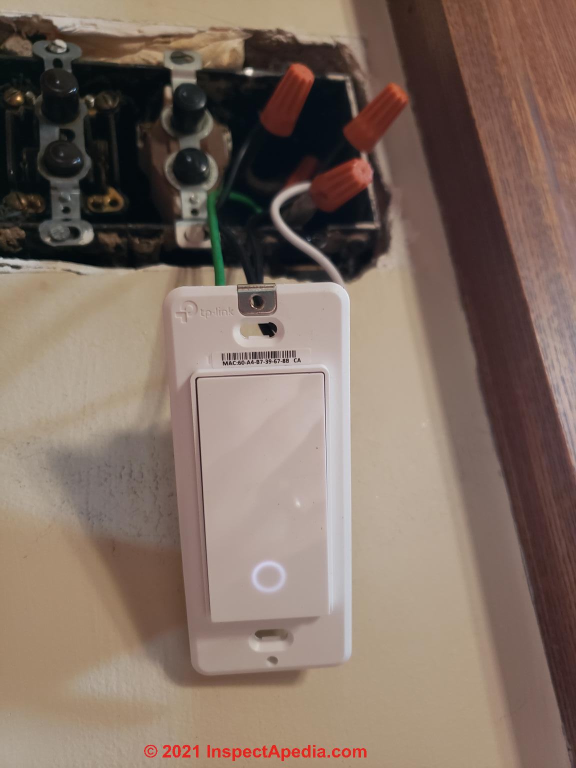
On 2022-01-18 by Ken - smart switch should work with knob and tube electrical wired circuits
@Inspectapedia Com Moderator,
So, I have been emailing back and forth with a tech. rep. from Kasa. They claim that the switch should work with the knob and tube.
To help, I rewired the Kasa HS200 switch so that I could take some pictures to send to them. I just sent them the pictures today.
I am sending them to you too so that you can see how I wired it. As you can see the switch is getting power but it still won't turn on the porch light.
On 2022-01-15 by Inspectapedia Com Moderator
@Ken,
I appreciate the discussion and look forward to the follow-up as working together will make us both smarter or at least you will make me smarter. Thanks.
On 2022-01-15 by Ken
@Inspectapedia Com Moderator,
OK I haven't looked at the manual. I will have a look at it. And, if nothing there, I will try to contact them.
Either way, I'll let you know what I find.
Two separate hot lines is an interesting idea. I did hook up one of these Kasa smart switches for a back porch light with an identical circuit where no knob and tube was involved and it worked!! Crazy eh!
On 2022-01-15 by Inspectapedia Com Moderator - smart switch isn't working
@Ken,
I haven't yet looked at the IO manual for your smart switch - we should both look at it and you might give the CO. a call, too.
I'm unclear on how power is fed into the switch and whether or not there'd be a problem if we feed power IN to the switch on two separate HOT lines that are in opposite phases vs. on the same phase (typically your panel supports two groups of 120V circuits, on two different phases).
On 2022-01-15 by Ken
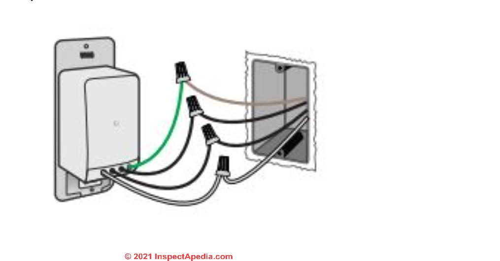
@Inspectapedia Com Moderator,
The attached is basically the wiring schematic. Sorry, I should have taken a picture of what I had installed. I have removed it and replaced it with the old mechanical timer switch just using the knob and tube wiring.
In my case, one of the black (hot) wires is a knob and tube wire that goes to a front porch light fixture. The other black (hot) wire goes to the closest plug receptical where there is power. I installed that.
So, it is a new 3 wire conductor. Since there is no ground in the knob and tube the ground wire in the new cable is not used, that is, there is no ground wire connection as shown in the diagram.
The neutral knob and tube is connected to the other white neutral that I installed. It boggles my mind why the smart switch gets power but it can't turn the porch light on. The smart switch is a Kasa HS200.
I'm in Toronto, Ontario, Canada. Cheers Ken
On 2022-01-14 by Inspectapedia Com Moderator - I still have some knob and tube wiring in my circa 1910 house.
@Ken,
I'd like to be more-helpful but from just your note I don't know what wires are present nor to what they are connected - what terminals, etc.
In general an electrical switch has no business needing the presence of a ground wire to operate properly - if it does I suspect a wiring error.
In other words, a "smart switch" should work properly regardless of the presence or absence of a ground wire.
However you should consider adding circuit grounds for improved safety, and depending on where you live you might be required to use a licensed electrician.
On 2022-01-13 by Ken
Question:
I still have some knob and tube wiring in my circa 1910 house.
I want to replace a manual switch with a smart switch. I have identified the hot and neutral wires of the knob and tube at the switch. I have run a two wire Romex type cable to the switch box as well. I hooked everything and the smart switch has power but it can't turn the light on.
Any suggestions?
Cheers
Ken
On 2021-05-30 by danjoefriedman (mod) - why is knob and tube wiring more-likely to overheat than modern electrical wiring?
@Hamp,
Thank you, that's a helpful question.
The original wire insulating jacket on knob and tube wiring and the wiring current or amperage rating presume that the wiring is installed as originally intended: was spaced in air.
That is, air could circulate freely around the wire, removing heat.
And where the wire passes through wood framing, of course, it runs through a ceramic tube; and of course it's supported off of surfaces by a ceramic knob.
Now if you're surround that same knob and tube wiring with insulation, it no longer has free circulating air around it.
The heat that is produced will not be so easily dissipated and therefore the insulation in fact may fail.
Now covered by insulation, the wiring overheats, thus there's an increased risk of a fire.
As a different example take a look at modern non-metallic electrical cable and you will see that the insulation is much more robust.
For any electrical wire, its insulating jacket is rated and intended to handle the heat that may be produced by the wire when the circuit is in high use without becoming hot, deteriorated and failing.
Failing wire insulation and overheated electrical wire is, of course, a fire hazard.
On 2021-05-29 by Hamp
Question: Why is the knob and tube wiring more likely to overheat if you insulate over it than today's modern wiring? Thanks.
On 2021-04-03 - by (mod) - kudos
@dennis stobinski, Thank you so much for your very nice note. It means a lot that you took the time and trouble to comment as you did, and of course I'm very happy that our information proved helpful to you.
Indeed we have worked hard for over twenty years to make information at InspectAPedia.com accurate, in-depth, and without bias, so I am of course very grateful when a reader reports that our website has been useful.
To that end, I would much appreciate hearing any comments, critique, suggestions, or further questions that you may have about any of our diagnosis/repair articles.
We are dedicated to making our information as accurate, complete, useful, and unbiased as possible: we very much welcome critique, questions, or content suggestions. Working together and exchanging information makes us better informed than any individual can be working alone.
On 2021-04-03 by dennis stobinski
I just wanted to say that I find this site to be an excellent resource. I wish more rehabbers would read this article to understand knob and tube wiring.
On 2021-02-12 - by (mod) - watch out that "dead" electrical wires might not be
Bob
If the wires test as "dead" you still need to take great care during demolition to treat the wires as "live" until you have visually traced the entire wire length.
I recall pushing my way into the attic of a 1920's home in New York - a space that had not been entered for many decades. I saw what looked like a pile of loose wires coiled up on the attic floor and figured ' "Gee these must be dead old wires someone left here" and on touching one of them got a terrific electrical shock.
Since then, when I've had to abandon rather than remove old un-used wires in a building, I tie the hot and neutral wires together, figuring that if someday someone finds another wire end that I didn't locate and if that someone connects that wire to a live source, the breaker or fuse will blow immediately.
Keep me posted on what you find.
On 2021-02-12 by Bob
In my 1925 home I have these knob and tube wires in the ceiling that have no juice even though everything else on the circuit works OK.
Before tearing out plaster to follow and inspect the wires, do you have any other troubleshooting recommendations?
On 2021-01-12 - by (mod) - tests indicate which K&T wires are hot and which are neutral
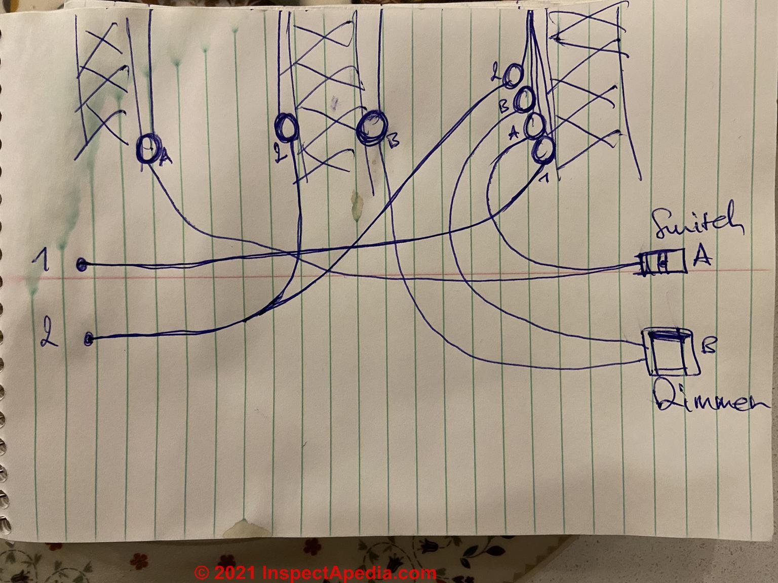
You going to want to test each wire with a multimeter or voltmeter to be sure you know where the incoming hot leads are. It looks as though there's a dimmer controlling a light somewhere and an on-off switch controlling a light somewhere.
But from just the drawing I don't know what's the incoming hot wire what's the neutral wire and where the light fixtures are.
If you're not familiar with using a voltmeter or digital multimeter safely you need to take care of because making a mistake could shock you or burn the place down. I suspect from what you already said that you know that perfectly well.
In its original installation knob and tube wiring insulation was black indicating hot wires and gray lighter color or including some white in its woven insulation to indicate the neutral wire.
Remember, there is no grounding conductor wire.
On 2021-01-12 by Lucas
Here is a diagram of the connections. Thanks!
On 2021-01-12 by (mod) - has this K&T wiring been modified or is it original?
Lucas
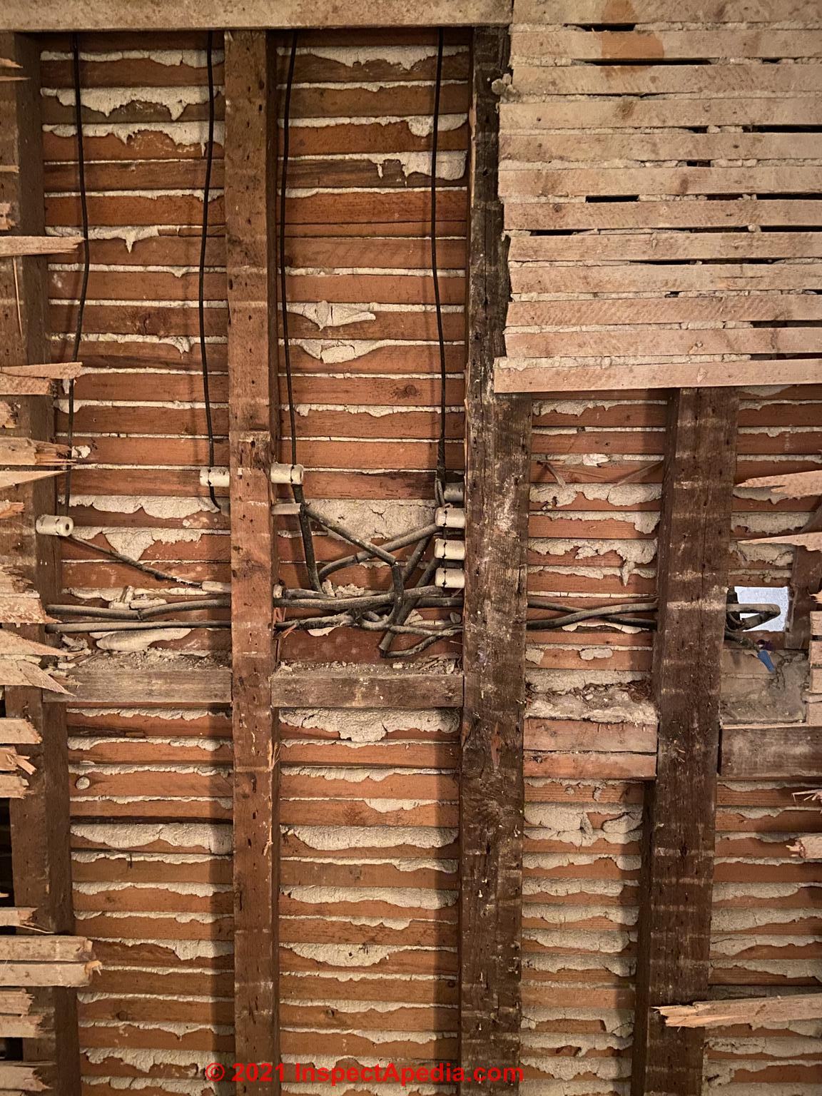 I can't see enough to tell you exactly what is being wired in your photo but I can say that I see what looks like a lot of knob and tube wire all jammed together in a small area, perhaps entering a junction box that I can't see.
And at the left of your photo I see new metal that suggests there have been modifications or additions to the wiring and I see what looks like an exposed splice that of course would be improper.
Most serious is that although the photos a bit blurry, it looks to me as if the wires in poor condition in some cases exposing legs of bare copper that I would consider to be unsafe and also an indicator that the wiring may have been damaged by overheating, rodents, or something else. I hope that you're planning to replace all of it.
Normally I like knob and tube wiring it I don't rush to replace it but if it's in poor condition or has been extensively modified or extended it's more likely to be unsafe.
On 2021-01-12 by Lucas
Hi, thanks a lot for all the info on the site, it’s very informative. I just opened a wall in our 1915 house and discovered this.
We already did some major renovations in the other part of the house and I knew we had K&T. I’m trying my best to understand how this is wired but it’s too hard...
On the right it ends with 1 switch (still connected in the back of the wall) and the one with wire nuts was a dimmer.
What I can’t figure out:
- is this is all K&T or was this modified at some point (it looks too messy and it’s missing tubes)
- are the two cables exiting on the left coming from the panel and powering all this or if the power coming from the 4 ceramics on the right stud?
Thanks a lot!
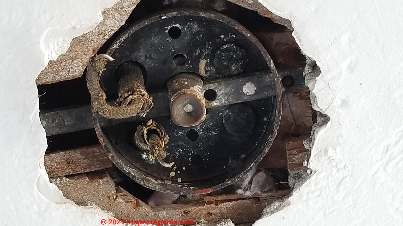
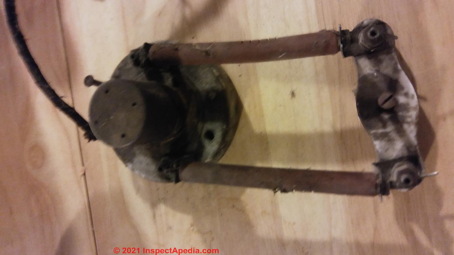
On 2020-10-17 - by (mod) - don't mistake old telephone wiring for knob and tube electrical circuits
I can't quite make out the photo, as it's a bit blurry John but it looks a bit like resistors and connectors I've seen in older homes where the telephone wires came into the building.
On 2020-10-17 by John
I recently removed the last part of an abandoned knob and tube wiring system and found this. Anyine know what this is called?
On 2020-05-17 by (mod) - is this knob and tube wiring?
 Jessica
That looks like a transformer, though I can't see all the wires;
I cannot see into the wall or ceiling from which this was pulled; take a look at the article above and note those white ceramic knobs and tubes - if you find those anywhere in your home then you've confirmed that it at least had and may still have this type of electrical wiring
On 2020-05-17 by Jessica
I was replacing my outlets with tamper resistant outlets when I came across the following. Is this k&t?
Thanks
On 2020-01-16 - by (mod) - safety concerns even where knob & tube wiring remains legal
William
First, in my OPINION, while existing, un-modified K&T wiring is perfectly legal in homes ain general, and thus it can be used, there are some important safety considerations that you should think about before continuing, some of which I think you're already thinking about given your question.
1. an existing knob and tube circuit can be used but it cannot be extended -
that is to add to it wires for lights, more receptacles, etc.
2. the existing K&T, as you note, is not grounded,
so it is important to use un-grounded receptacles so as not to fool users into thinking a ground is present (and possibly creating an unsafe condition by allowing plugging-in of a device that requires grounding for safe use) OR you'd have to run a ground wire along that circuit and into every electrical box on it.
3. Local grounds to water pipes is not a safe "solution:
While grounding water pipes is a good safety feature (so you don't get electrocuted when a toaster falls into the sink) you would not simply rely on pipes here and there in a building as a safe electrical ground - the pipes may be interrupted by a diaelectric fitting or may otherwise not provide a continuous ground;
Some communities permit using an existing water main entering from underground to serve as one of the two grounds required; the other is a grounding electrode. Look in the ARTICLE INDEX under GROUNDING to see details.
4. If insulation has been added the knob and tube wiring is unsafe:
This is my opinion and is the worst news.
Knob and Tube wiring was in my opinion an excellent and safe wiring method in that it used ceramic knobs and tubes plus running wires in open air to provide wiring that wasn't likely to overheat or short together.
BUT now everything has changed: when insulation is blown into walls, the wiring therein that used to run in open air now is covered by insulation. It can not possibly run as cool as it did originally; the insulation on the wire and its approval as "safe" presumed the wires were in open air.
So the insulated circuit is less safe and at greater risk of overheating.
I'm not sure about your question:
"I want to safely secure those wires and finish wiring the first floor and basement with the proper wiring. How do I incorporate this wiring to accommodate the wiring going to the second story ."
But you can either leave the existing K&T but make it comply as we've outlined in this article series, and risk overheating in insulated cavities - (keep fusing to 15A or less and take care not to tax the circuit, e.g. by running electric heaters on it)
or
you can abandon the circuit and run a new one or multiple ones to upper floors.
On 2020-01-16 by William J. Petersen
I have knob and tube wiring going into my second story of my home as it enters the walls from below at the basement I want to safely secure those wires and finish wiring the first floor and basement with the proper wiring. How do I incorporate this wiring to accommodate the wiring going to the second story . The walls have blown in insulation.
Someone had changed the electric plug ins to three prong outlets but no ground, could I run a separate ground wiring and connect it to my other electrical services that are grounded to the water pipe. I plan on adding a separate ground rod to make sure the safety of the ground.
On 2019-11-14 - by (mod) - knob and tube wiring blew a fuse that won't re-set
If there is simply a fuse that's blown or a circuit breaker that stripped you can reset the breaker or replace the fuse.
It's also possible that a limited error such as a damaged electrical receptacle caused the fuse to blow or circuit breaker to trip: a small, local electrical repair.
Watch out: However if the electrical receptacle itself is damaged and causing a short circuit that it needs to be replaced. Leaving it in place without that would be unsafe.
I'm a bit surprised for the laptop alone would possibly be enough to trip a breaker or blown fuse. There's something else going on there. Most likely it's a defective receptacle. Replace it.
On 2019-11-13 by Arnold
Hi there i have knob and tube in a section of my house which my inspector considered safe when we bought the property.
Not too long ago i overloaded the circuit by plugging a laptop into an outlet on the ground floor so now all my outlets and lights in my master bedroom and porch are not working. Is there a way to reset this without having to go through a costly overhaul.
I dont intend to use the outlet that started this any more. Many thanks
On 2019-10-01 - by (mod) - which agency is an expert on knob and tube wiring?
Rosie
Your local building code enforcement department's electrical inspector should know about Knob and Tube (K&T) wiring.
Indeed use of extension cords and power strips can easily overload a circuit - that ought to cause a breaker to trip or fuse to blow, but over-fusing, damaged wiring, damaged power strip or something else might indeed start a fire.
OPINION: in such a case, there remains an indirect relation ship between the primary cause (bad power strip or line cord or plug - for example) and the secondary cause of the fire that might include
- an inadequate number of electrical circuits
- overloaded individual electrical circuits
- over-fusing of those circuits to stop what an occupant or owner regards as "nuisance" tripping of breakers and fuses, in turn leading to overheated wires and a building fire
- absence of an electrical grounding conductor on those K&T circuits - meaning that a typical power strip that includes receptacles for three-prong "plugs" or grounded plugs is misleading since no ground is present, and in fact the
power strip's own plug may have been modified or adapted to fit into the two-prong K&T wall receptacle
FYI K&T is legal and is not required to be removed from a building provided
- the circuit has not been extended (extensions are not approved)
- the circuit is not damaged
- the circuit is properly fused
But as you'll read in this article series, the assumption that an old K&T circuit is "safe" might be a mistake. For example, simply blowing insulation into a wall or ceiling where K&T was run changes the environment of that wire: it is no longer suspended in air, therefore it may overheat.
On 2019-10-01 by RosieF
Does anyone know who/which agency would be an authority on knob and tube wiring?
I live in a building over 100 years old whose unscrupulous landlords never bothered to update the wiring. It caught on fire a few years ago and the landlord blames one tenants for an overcharged power strip. While the power strip no doubt was the spark, the fact that it spread so quickly and pervasively was most-likely due to the faulty wiring, whose conditions were questionable.
On 2019-06-14 - by (mod) - OK to use un-grounded wall plug appliances in un-grounded electrical receptacles & knob and tube wiring?
Basically if the line cord on your appliances a three-pronged plug then it wants to be in a grounded receptacle. If the line port on your appliances a two prong plug them it's not looking for a ground and so you're not getting anything up by using it on a knob and tube circuit.
Of course that is assuming that the circuit is safe and has not been damaged or is not unsafe for some other reason.
On 2019-06-13 by Joe
Is it still considered acceptable to plug an appliance with a 2 prong cord into an ungrounded 2 prong outlet with knob and tube wiring? If so, where is the line between what is ok and what becomes questionable?
...
Continue reading at OLD HOUSE ELECTRICAL SYSTEMS or select a topic from the closely-related articles below, or see the complete ARTICLE INDEX.
Or see KNOB & TUBE WIRING FAQs - questions & answers posted originally at this page
Or see these
Recommended Articles
- ASBESTOS ELECTRICAL WIRE INSULATION
- ELECTRICAL PANEL FUSED NEUTRAL WIRE HAZARDS
- FALSE GROUND at RECEPTACLES
- FALSE GROUND, BOOTLEG & FLICKERING LIGHTS
- KNOB & TUBE WIRING of Proper and Improper Knob and Tube Wiring Details
- OLD ELECTRICAL WIRING HISTORY
- OLD ELECTRICAL WIRING TYPES
- OLD HOUSE ELECTRICAL SYSTEMS
- WET SUBMERGED K&T WIRING
Suggested citation for this web page
KNOB & TUBE WIRING at InspectApedia.com - online encyclopedia of building & environmental inspection, testing, diagnosis, repair, & problem prevention advice.
Or see this
INDEX to RELATED ARTICLES: ARTICLE INDEX to ELECTRICAL INSPECTION & TESTING
Or use the SEARCH BOX found below to Ask a Question or Search InspectApedia
Ask a Question or Search InspectApedia
Try the search box just below, or if you prefer, post a question or comment in the Comments box below and we will respond promptly.
Search the InspectApedia website
Note: appearance of your Comment below may be delayed: if your comment contains an image, photograph, web link, or text that looks to the software as if it might be a web link, your posting will appear after it has been approved by a moderator. Apologies for the delay.
Only one image can be added per comment but you can post as many comments, and therefore images, as you like.
You will not receive a notification when a response to your question has been posted.
Please bookmark this page to make it easy for you to check back for our response.
Our Comment Box is provided by Countable Web Productions countable.ca
Citations & References
In addition to any citations in the article above, a full list is available on request.
- [2] Timothy Hemm, Yucala, CA, contributed various photographs of electrical equipment installed in California buildings. Mr. Hemm can be contacted at TimHemm@yahoo.com
- [3] Kosta Trivlidis Home Inspector (AIBQ) National Home Inspector (NHICC) CSI Inspections Inc. csiinspections.ca kosta@csiinspections.ca
- "Electrical System Inspection Basics," Richard C. Wolcott, ASHI 8th Annual Education Conference, Boston 1985.
- "Simplified Electrical Wiring," Sears, Roebuck and Co., 15705 (F5428) Rev. 4-77 1977 [Lots of sketches of older-type service panels.]
- "How to plan and install electric wiring for homes, farms, garages, shops," Montgomery Ward Co., 83-850.
- "Simplified Electrical Wiring," Sears, Roebuck and Co., 15705 (F5428) Rev. 4-77 1977 [Lots of sketches of older-type service panels.]
- "Home Wiring Inspection," Roswell W. Ard, Rodale's New Shelter, July/August, 1985 p. 35-40.
- "Evaluating Wiring in Older Minnesota Homes," Agricultural Extension Service, University of Minnesota, St. Paul, Minnesota 55108.
- "Electrical Systems," A Training Manual for Home Inspectors, Alfred L. Alk, American Society of Home Inspectors (ASHI), 1987, available from ASHI. [DF NOTE: I do NOT recommend this obsolete publication, though it was cited in the original Journal article as it contains unsafe inaccuracies]
- "Basic Housing Inspection," US DHEW, S352.75 U48, p.144, out of print, but is available in most state libraries.
- In addition to citations & references found in this article, see the research citations given at the end of the related articles found at our suggested
CONTINUE READING or RECOMMENDED ARTICLES.
- Carson, Dunlop & Associates Ltd., 120 Carlton Street Suite 407, Toronto ON M5A 4K2. Tel: (416) 964-9415 1-800-268-7070 Email: info@carsondunlop.com. Alan Carson is a past president of ASHI, the American Society of Home Inspectors.
Thanks to Alan Carson and Bob Dunlop, for permission for InspectAPedia to use text excerpts from The HOME REFERENCE BOOK - the Encyclopedia of Homes and to use illustrations from The ILLUSTRATED HOME .
Carson Dunlop Associates provides extensive home inspection education and report writing material. In gratitude we provide links to tsome Carson Dunlop Associates products and services.
 | HOME | ABOUT | ASK a QUESTION | CONTACT | CONTENT USE POLICY | DESCRIPTION | POLICIES | PRIVACY | |
| © 2024 - 1985 Publisher InspectApedia.com - Daniel Friedman | |||||||||