
InspectAPedia® FREE Encyclopedia of Building & Environmental Construction, Diagnosis, Maintenance & Repair |
Question? Just ask us! InspectAPedia
|
 Multiwire Branch Circuits
Split-Wired Receptacles - Electrical Wiring Safety Requirements
- POST a QUESTION or COMMENT about Multiwire Electrical Circuits & Their Electrical Safety
Shared neutral wires, split-wired receptacles, multi-wired branch circuit wiring:
This article provides an explanation of electrical wiring and safety defects regarding split-wired (multi-wired or shared neutral) electrical receptacles. We include electrical code citations for mutliwire circuits.
InspectAPedia tolerates no conflicts of interest. We have no relationship with advertisers, products, or services discussed at this website.
Split Wired Electrical Receptacles
Here we discuss the following: the definition of multi wire or shared neutral electrical circuits. Why are multi-wire electrical circuits used? How should multi wire circuits be wired-up?
How should mult-wire circuits be fused or connected to circuit. breakers?How to inspect multi wired electrical circuits
Article Contents
A Multiwire Branch Circuit (in the electrical code) is defined as a branch circuit that consists of two or more ungrounded conductors (two or more "hot" wires) that have a voltage between them (they are not on the same electrical phase and so are connected to different buses in the electrical panel), and a grounded conductor (the neutral wire) that has equal voltage between it and each ungrounded conductor (hot wire) of the circuit and that is connected to the neutral or grounded conductor of the system. (Paraphrasing NEC Article 100).
In plain English, a "multiwire branch circuit" or "split-wired receptacles" means that two hot wires are sharing a neutral wire.
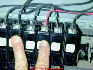
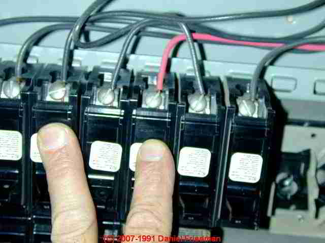
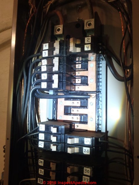
Our photo (above-left) illustrates how a shared neutral circuit can be easily fouled-up and made dangerous.
The two circuit breakers I am pointing to in this electrical panel have been inserted into the panel in a position so that they are on the same phase or power circuit.
As a result the shared neutral wire will be carrying double its intended load rather than a fraction of it.
Simply moving one of these breakers to a different panel position could correct the problem but unless the two breakers are placed side by side and connected with a common trip tie the wiring would still be unsafe.
Even then not all such installations are proper and safe. See
details at CIRCUIT BREAKER HANDLE TIES
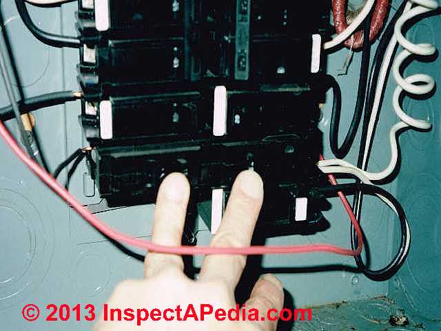
A split-wired receptacle [electrical outlet] is a duplex [two openings for plugs] electrical receptacle that has been converted functionally into two single, receptacles that are individually partly or completely electrically independent. The photograph shows a red and black wire pair powering a shared neutral circuit.
They are improperly connected in this panel. This article explains why that is the case and what to do about it.
Each receptacle opening of the pair is individually supplied with electricity by its own electrical circuit and fuse or circuit- breaker. Thus there is one electrical circuit for each individual plug-receptacle opening in the individual duplex electrical outlet.
A split-wired receptacle [electrical outlet] is a duplex [two openings for plugs] electrical receptacle that has been converted functionally into two single, receptacles that are individually partly or completely electrically independent. Each receptacle opening of the pair is individually supplied with electricity by its own electrical circuit and fuse or circuit- breaker.
Thus there is one electrical circuit for each individual plug-receptacle opening in the individual duplex electrical outlet.
By providing two power sources at one duplex electrical receptacle, split-wired receptacles permit the user to plug-in two power-hungry electrical devices at the same location without overloading and thus tripping a circuit breaker or blowing a fuse as might happen if the same two power-hungry devices were operated simultaneously on a single circuit.
[Imagine trying to simultaneously operate both a large electric toaster and a microwave on the same kitchen circuit.]
In completely electrically-independent split-wired receptacles, each receptacle also has its own independent neutral wire and possibly ground wire back to the electric panel. In a multi-wired or shared-neutral receptacle, a single neutral wire is shared by both of the independently-powered receptacles.
How to Fuse Multiwire (shared-neutral) Electrical Branch Circuits
 Use of linked double-pole or two-pole circuit breakers is recommended:
Pending further research and development of authoritative citations, the
following is the opinion of the author:
Use of linked double-pole or two-pole circuit breakers is recommended:
Pending further research and development of authoritative citations, the
following is the opinion of the author:
Multiwire branch circuits should be protected by a double-pole common-internal trip circuit breaker, including the physical "trip tie" which bonds the two circuit breaker switches together.
This is a safety measure which protects people working on the building wiring and which helps assure that the circuit is wired properly at the panel. Even if local building inspectors do not require this measure we recommend it as a safety item and as good construction practice.
Background: the author has observed two electrical wiring hazards associated with failure to observe the recommendation above.
- Case-1: both breakers placed on same panel bus:
Performing work on an electrical panel in which a multi-wire branch circuit was not wired using a double-pole common-trip circuit breaker, an electrician relocated one of the individual breakers such that both of the multi-wire feeds were on the same electrical bus.
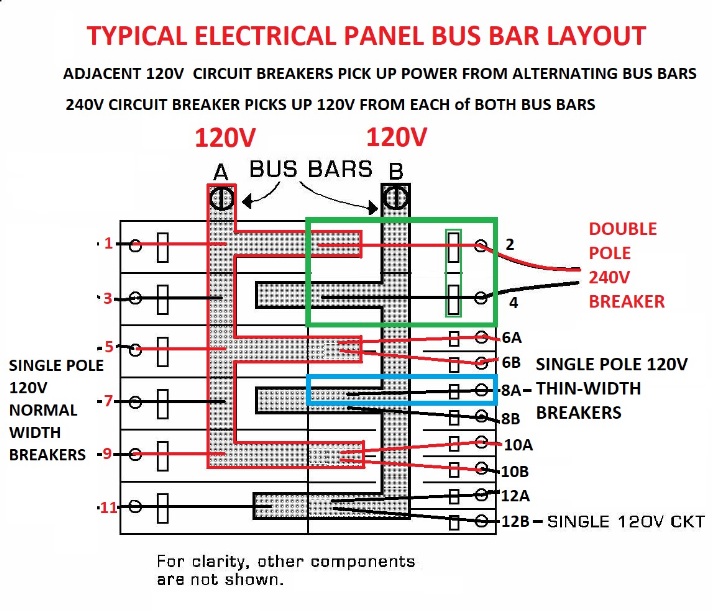
In our sketch, using the narrow-width circuit breakers 10A and 10B, if wired as a multi-wired circuit, would both be connected to the same bus and same phase. This is an improper wiring hook-up because this placed both breakers on the same electrical phase in the electric panel.
When both circuits were in maximum use the result was a neutral wire current which exceeded the permitted rating.
If a double-pole internal trip breaker had been used it would have forced the two feed circuits to be on opposite electrical phases in the panel, thus reducing rather than increasing the observed current on the neutral wire.
[Two electrical currents in opposing electrical phase, introduced on the same wire, are self-canceling. I am speaking approximately, since in common residential electrical wiring, the two panel buses are not in exactly-opposite electrical phases.]
If instead the electrician made a multi-wire branch circuit pair by using positions 10B and 12A in our sketch, OR from positions 9 and 11 in the sketch using normal full-width circuit breakers, that would work correctly because the two circuits sharing a common neutral would have pulled power from two different panel bus bars.
Photo below: an Eaton Cutler Hammer electrical panel showing an example of the alternating bus position layout that is also described by our sketch above.
- Case-2: neutral wire energized at a location where power was "off": Performing
repairs on an individual electrical circuit which used a shared neutral wire, the
worker turned off the circuit breaker feeding an electrical receptacle in order to
install a new outlet at that location.
After confirming (by simple neon tester) that power was "off" at the receptacle, the worker began re-wiring the new device in place.
Meanwhile the worker's assistant plugged-in and began operating a power-hungry electrical tool at another electrical circuit in the building - a circuit which shared the same neutral wire as the one being worked-on.
The worker, on touching both a ground path (BX cable) and the neutral wire, was shocked.[Personal experience of author.]
For a detailed article about how multi-wire electrical circuits are wired, see the ASHI Technical Journal, Vol 2 No 1 Winter 1992 p. 27-30 In addition to the author, Neal Macneale III, Douglas Hansen and Daniel Friedman edited and illustrated that material.
Explanation of Shared Neutral Electrical Circuit Wiring Requirements
- Double pole breakers can be required by National Electrical Code for split receptacles, as per paragraph 210-4-b.
- Using a double-pole breaker assures that the two legs of the circuit will be
forced (in most panels) to opposite legs of the 240-volt panel - a requirement
when circuits use a shared neutral, such as in multiwire branch circuits.
If individual 120V breakers are used, it's possible for a future modification or rearrangement of breakers in the panel to in advertently move one or both individual breakers so that they both end up on the same 120V leg of the panel - which is improper when a shared neutral is involved. (Improper because the shared unbalanced load could exceed the rating of the wire.) - Using a double-pole assures that if one leg of the circuit is being turned
off for electrical repair/modification work in the building, the other leg is
forced off as well.
Otherwise it is possible for the mechanic to be shocked while working on the circuit, since the neutral wire of the supposedly "dead" circuit could be carrying current from the sister "live" circuit.
National Electrical Code Citations for Multi Wire and Split Wire Devices
- The 2008 National Electrical Code, 210.4(B) Multiwire Branch Circuits, now requires that effective 1 January 2008,information about conductors of multiwire branch circuits originating from the same panelboard or distribution equipment has been relocated to 210.4(A).
Now 210.4(B) addresses disconnecting means for simultaneously disconnecting all ungrounded conductors of all multiwire branch circuits.
Simultaneously disconnecting all conductors of multiwire branch circuits is now expanded to all multiwire branch circuits, not just those that supply more than one device mounted on the same yoke or mounting strap. -- Minnesota Electrical Association. - NEC Paragraph 210-4 addresses multiwire branch circuits.
- NEC 210-4-b makes clear that split receptacles must be protected by a
simultaneous disconnect to all ungrounded (hot) conductors (i.e. use a
double-pole breaker with a common trip tie installed).
NEC Paragraph 210-4 addresses multiwire branch circuits.
See details at CIRCUIT BREAKER HANDLE TIES - Split-receptacle means each half of a duplex receptacle is wired to a different "polarity" or phase and the single grounded conductor (neutral) is used). NEC Paragraph 210-4 addresses multiwire branch circuits.
Electrical Code Notes on Shared Neutral and Split Wired Electrical Devices
ASHI Member Frank Luciano spoke with Al Weiss, New York State building code authority (Building code support office at World Trade Center, New York City) regarding the requirement for linking or common-trip ties for these circuits.
Mr. Weiss' opinion was that if he sees individual breakers in the panel on a multiwire circuit he will not call it out as an issue for failure to link the breakers together.
The discussion did not review possible relocation of one of the breakers to the same phase or "leg" of the panel as the other.
Mr. Weiss' interpretation of the National Electric Code (NEC) is that if, on a multiwire circuit, the two phases are wired to the same electrical receptacle (upper portion to one phase, lower to another phase, by breaking the tie on the receptacle sides) then a common-trip breaker should be usedOn that circuit.
He also opined that if breakers were wired in parallel, rather than in series, as is done in some states, then common trip ties are not required.
Receptacles for Multi-Wire 30A 240VAC Circuits
Question: can I use a single 30A multi-wire 240VAC circuit to power multiple 240V appliances?
Ron said:
I have a small shop in my garage with three 240v appliances (dust collector - 3A, heater - 12A, table saw - 9A).
Can I create a single 30A branch circuit to pick up the outlets for all these appliances in a single circuit?
Reply: yes to the circuit but the electrical receptacles, wire, and circuit amapacity must meet-code
A 30A circuit would handle the load (3+12+9 = 24A) without tripping the breaker when all three are in use at once.
Confirm however that the "outlet" you intend to use (if you mean a wall plug receptacle) and every component in the circuit (wire size, connectors, fusing) are all matched or rated for 30A.
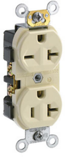
Photo: a Leviton 5842-i electrical receptacle rated for use up to 20A of load [Click to enlarge any image]
Watch out: do not install a 20A receptacle on a 30A circuit. Take note, however that the Leviton 5842-i receptacle (illustrated here) and suggested by reader Cortese, is rated for use on a 20A circuit, NOT on a 30A circuit.
Use of a single circuit for devices drawing 24 Amps total would thus not be safely supported on a 20A circuit but would be ok on a 30A circuit. Also no single device can draw more than 80% of the circuit rating (.8 x 30 = 24A so you'd be OK on that point).
Reader follow-up: I'd like to use 20A outlets on the 30A circuit
 MY QUESTION was about multiple outlets on a multi wire branch circuit is repeated here:
I have a small shop in my garage with three 240v appliances (dust collector - 3A, heater - 12A, table saw - 9A). Can I create a single 30A branch circuit to pick up the outlets for all these appliances in a single circuit?
If possible, I'd like to use 20A outlets on the 30A circuit (nothing plugged in would come standard with a 30A plug, so I'd have to re-plug all 3 of the appliances I listed above)
Reply: do not use 20A receptacles on a 30A circuit - it's unsafe and violates the US NEC
I agree that re-plugging all of your devices to use a 30A-rated electrical receptacle is a pain.
Watch out: But you should not use a 20-A rated device (in this case a wall receptacle) on a 30A circuit. Use a receptacle rated for 30 Amps.
It's a case of "nothing goes wrong until something goes wrong"
Even though you don't plan on plugging in anything at those receptacles that draws 30A and thus you would not have a problem, you can't know what some future dope will do in the building after you and I are long gone.
I guess you could argue that it's only the receptacle itself that's at risk of overheating damage, and since the receptacle itself is physically designed to only accept plugs on 20A appliances or devices, you're "safe".
But the U.S. National Electrical code guys, hoping to keep us out of trouble, think otherwise.
Such an installation,, as Mike Holt and other experts have pointed out, would be a violation of the U.S. NEC 210.21(B)
210.21(B)(1) A single receptacle installed on an individual branch circuit shall have an ampere rating not less than that of the branch circuit.
or
210.21(B)(3) Where connected to a branch circuit supplying two or more receptacles or outlets, receptacle ratings shall conform to the values listed in Table 210.21(B)(3), or, where rated higher than 50 amperes, the receptacle rating shall not be less than the branch-circuit rating.
US NEC Text Excerpts: ARTICLE 210 — BRANCH CIRCUITS
210.20 Overcurrent Protection. Branch-circuit conductors
and equipment shall be protected by overcurrent protective
devices that have a rating or setting that complies
with 210.20(A) through (D).
(A) Continuous and Noncontinuous Loads. Where a branch circuit supplies continuous loads or any combination of continuous and noncontinuous loads, the rating of the overcurrent device shall not be less than the noncontinuous load plus 125 percent of the continuous load.
Exception: Where the assembly, including the overcurrent
devices protecting the branch circuit(s), is listed for operation
at 100 percent of its rating, the ampere rating of the
overcurrent device shall be permitted to be not less than the
sum of the continuous load plus the noncontinuous load.
(B) Conductor Protection. Conductors shall be protected
in accordance with 240.4. Flexible cords and fixture wires
shall be protected in accordance with 240.5.
(C) Equipment. The rating or setting of the overcurrent protective device shall not exceed that specified in the applicable articles referenced in Table 240.3 for equipment.
(D) Outlet Devices. The rating or setting shall not exceed that specified in 210.21 for outlet devices.
![]() Illustration inserted by editor - this is not part of the US NEC: an Arrow-Hart 30A locking receptacle. Similar devices are produced by Leviton (L8-30R) and other manufacturers.
Illustration inserted by editor - this is not part of the US NEC: an Arrow-Hart 30A locking receptacle. Similar devices are produced by Leviton (L8-30R) and other manufacturers.
210.21 Outlet Devices. Outlet devices shall have an ampere rating that is not less than the load to be served and shall comply with 210.21(A) and (B).
(A) Lampholders. Where connected to a branch circuit having a rating in excess of 20 amperes, lampholders shall be of the heavy-duty type. A heav-duty lampholder shall have a rating of not less than 660 watts if of the admedium type, or not less than 750 watts if of any other type.
(B) Receptacles.
(1) Single Receptacle on an Individual Branch Circuit.
A single receptacle installed on an individual branch circuit shall have an ampere rating not less than that of the branch circuit.
Exception No. 1: A receptacle installed in accordance with 430.81(B).
Exception No. 2: A receptacle installed exclusively for the use of a cord-and-plug-connected arc welder shall be permitted to have an ampere rating not less than the minimum branch-circuit conductor ampacity determined by 630.11(A) for arc welders.
(2) Total Cord-and-Plug-Connected Load. Where connected to a branch circuit supplying two or more receptacles or outlets, a receptacle shall not supply a total cord-and-plug-connected load in excess of the maximum specified in Table 210.21(B)(2).
Table 210.21(B)(2) Maximum Cord-and-Plug-Connected Load to Receptacle
(2).jpg)
[Click to enlarge any image]
(3) Receptacle Ratings. Where connected to a branch circuit supplying two or more receptacles or outlets, receptacle ratings shall conform to the values listed in Table 210.21(B)(3), or, where rated higher than 50 amperes, the receptacle rating shall not be less than the branch-circuit rating.
Exception No. 1: Receptacles for one or more cord-and-plug-connected arc welders shall be permitted to have ampere ratings not less than the minimum branch-circuit conductor ampacity permitted by 630.11(A) or (B), as applicable for arc welders.
Exception No. 2: The ampere rating of a receptacle installed for electric discharge lighting shall be permitted to be based on 410.62(C).
Table 210.21(B)(3) Receptacle Ratings for Various Size
(3).jpg)
(4) Range Receptacle Rating. The ampere rating of a range receptacle shall be permitted to be based on a single range demand load as specified in Table 220.55.
210.23 Permissible Loads. In no case shall the load exceed the branch-circuit ampere rating. An individual branch circuit shall be permitted to supply any load for which it is rated. A branch circuit supplying two or more outlets or receptacles shall supply only the loads specified according to its size as specified in 210.23(A) through (D) and as summarized in 210.24 and Table 210.24.
(A) 15- and 20-Ampere Branch Circuits. A 15- or 20- ampere branch circuit shall be permitted to supply lighting units or other utilization equipment, or a combination of both, and shall comply with 210.23(A)(1) and (A)(2).
Exception: The small-appliance branch circuits, laundry branch circuits, and bathroom branch circuits required in a dwelling unit(s) by 210.11(C)(1), (C)(2), and (C)(3) shall supply only the receptacle outlets specified in that section.
(1) Cord-and-Plug-Connected Equipment Not Fastened in Place. The rating of any one cord-and-plug-connected utilization equipment not fastened in place shall not exceed 80 percent of the branch-circuit ampere rating.
(2) Utilization Equipment Fastened in Place. The total rating of utilization equipment fastened in place, other than luminaires, shall not exceed 50 percent of the branch- circuit ampere rating where lighting units, cord-and-plug- connected utilization equipment not fastened in place, or both, are also supplied.
(B) 30-Ampere Branch Circuits. A 30-ampere branch circuit shall be permitted to supply fixed lighting units with heavy-duty lampholders in other than a dwelling unit(s) or utilization equipment in any occupancy. A rating of any one cord-and-plug-connected utilization equipment shall not exceed 80 percent of the branch-circuit ampere rating.
Source:
- Earley, Mark W., & Jeffrey S. Sargent, NFPA 70, NEC 2011 HANDBOOK, [PDF] retrieved 2018/04/12, original source: https://ia800503.us.archive.org/4/items/NationalElectricalCode/National%20Electrical%20Code.pdf
Effects of Multiple or Gang Plug Adapters on Split-Recptacle-wired electrical circuits
This topic has moved to ELECTRICAL WALL PLUG ADAPTERS - using a wall plug adapter, power strip, surge protector, or electrical spike protection device
Reader Comments, Questions & Answers About The Article Above
Below you will find questions and answers previously posted on this page at its page bottom reader comment box.
Reader Q&A - also see RECOMMENDED ARTICLES & FAQs
On 2020-07-01 by Chris L - no requirement for pigtailing electrical receptacles if not on shared neutral multiwire branch circuit
Local jurisdiction uses NEC 2017 code.
Inspector is claiming that every receptacle in a normal single phase circuit must be connected with pigtails, citing 300.13.B. In other words, he will not allow the use of the second set of terminals on the outlet to be used to connect to the next outlet down the line.
300.13.B applies to multiwire circuits
. I don't believe that applies here.
Every reference I can find shows that it is OK to use that second set of terminals. Any thoughts? I don't want to start a battle with the inspector, because he basically holds all the cards, but I don't believe his interpretation is correct.
This Q&A were posted originally
at ELECTRICAL RECEPTACLE COVER PLATES
On 2020-07-01 - by (mod) - Inspector is claiming that every receptacle in a normal single phase circuit must be connected with pigtails, citing 300.13.B.
Chris
Well that's one we've not heard before - not for a circuit that is not multi-wire.
The second set of terminals on electrical receptacles were specifically placed by the manufacturer to permit wiring of a downstream device. Pigtailing is an acceptable alternative but will often require that every electrical box be increased in size as you've got more splices i the box.
My understanding is that US NEC 300.13.B is only for multiwire circuits - that means you've got a shared neutral. Is that your situation?
The U.S. National Electrical Code NEC Citation on mult-wire branch circuit wiring is as follows:
US NEC 300.13(B) Device Removal.
In multiwire branch circuits, the continuity of a grounded conductor shall not depend on device connections such as lampholders, receptacles, and so forth, where the removal of such devices would interrupt the continuity.
The code commentary on that notes:
Grounded conductors (neutrals) of multiwire branch circuits supplying receptacles, lampholders, or other such devices are not permitted to depend on terminal connections for continuity between devices.
For such installations (3- or 4-wire circuits), a splice is made and a jumper is connected to the terminal, unless the neutral is looped; that is, a receptacle or lampholder could be replaced without interrupting the continuity of energized downstream line-to-neutral loads (see commentary to 300.14).
Opening the neutral could cause unbalanced voltages, and a considerably higher voltage would be impressed on one part of a multiwire branch circuit, especially if the downstream line-to-neutral loads were appreciably unbalanced.
This requirement does not apply to individual 2-wire circuits or other circuits that do not contain a grounded (neutral) conductor.
So if you are using a shared neutral the inspector has a solid basis for opinion.
You're right that the local code inspector has the final legal authority. Start by getting him or her on the same side, ask why, code citation, support.
On 2020-07-01 by Chris L
I do not have a shared neutral. I'll try to talk to him nicely some more. Thanks!
On 2020-07-01 - by (mod) -
Sounds good
Keep me posted
On 2020-07-08 by Chris L
Inspector came out, looked around, mentioned a couple of minor (non-electrical) things to take care of, and NEVER ONCE mentioned this issue.
I sure wasn't going to bring it up! He was arguing with me about it on the phone the other day so I doubt that he just forgot it, so maybe he reconsidered his position. In any case, it seems to have turned into a non-issue. Thanks!
On 2020-07-08 - by (mod) - no requirement for pigtailing electrical receptacles if not on shared neutral multiwire branch circuit
Thanks so much for the update, Chris, that will help other readers.
A non-issue is a nice resolution.
See more explanation of multiwire branch circuit wiring and troubles found at MULTI-WIRE CIRCUITS
...
Continue reading at ELECTRICAL CIRCUIT ID, MAP & LABEL or select a topic from the closely-related articles below, or see the complete ARTICLE INDEX.
Or see MULTI-WIRE CIRCUIT FAQs - questions & answers about multi-wire branch circuits posted originally at the end of this page
Or see these
Recommended Articles
- AFCIs ARC FAULT CIRCUIT INTERRUPTERS
- AFCI GFCI WIRING, TESTING & SAFETY where multi-wire circuits are a particular problem
- ELECTRICAL CIRCUIT ID, MAP & LABEL
- ELECTRICAL CIRCUITS, SHORTS
- ELECTRICAL OUTLET, HOW TO ADD & WIRE
- MULTI-WIRE CIRCUITS
Suggested citation for this web page
MULTI-WIRE CIRCUITS at InspectApedia.com - online encyclopedia of building & environmental inspection, testing, diagnosis, repair, & problem prevention advice.
Or see this
INDEX to RELATED ARTICLES: ARTICLE INDEX to ELECTRICAL INSPECTION & TESTING
Or use the SEARCH BOX found below to Ask a Question or Search InspectApedia
Ask a Question or Search InspectApedia
Questions & answers or comments about Multiwire Electrical Circuits & Their Electrical Safety.
Try the search box just below, or if you prefer, post a question or comment in the Comments box below and we will respond promptly.
Search the InspectApedia website
Note: appearance of your Comment below may be delayed: if your comment contains an image, photograph, web link, or text that looks to the software as if it might be a web link, your posting will appear after it has been approved by a moderator. Apologies for the delay.
Only one image can be added per comment but you can post as many comments, and therefore images, as you like.
You will not receive a notification when a response to your question has been posted.
Please bookmark this page to make it easy for you to check back for our response.
Our Comment Box is provided by Countable Web Productions countable.ca
Citations & References
In addition to any citations in the article above, a full list is available on request.
- 01/17/00 note: thanks to David Shapiro for additional editing comments
- The Minnesota Electrical Association has posted an article of the most important electrical code changes for 2008 at electricalassociation.com/catalog/2008NECTop10.aspx - by Michael J. Johnston, IAEI
- Multi-wire electrical branch circuits For a detailed article about how these circuits are wired, see the ASHI Technical Journal, Vol 2 No 1 Winter 1992 p. 27-30 In addition to the author, Neal Macneale III, Douglas Hansen and Daniel Friedman edited and illustrated this material. Reprints of the ASHI Technical Journal are available from ASHI - www.ashi.com or copies of individual articles may be available from the authors.
- In addition to citations & references found in this article, see the research citations given at the end of the related articles found at our suggested
CONTINUE READING or RECOMMENDED ARTICLES.
- Carson, Dunlop & Associates Ltd., 120 Carlton Street Suite 407, Toronto ON M5A 4K2. Tel: (416) 964-9415 1-800-268-7070 Email: info@carsondunlop.com. Alan Carson is a past president of ASHI, the American Society of Home Inspectors.
Thanks to Alan Carson and Bob Dunlop, for permission for InspectAPedia to use text excerpts from The HOME REFERENCE BOOK - the Encyclopedia of Homes and to use illustrations from The ILLUSTRATED HOME .
Carson Dunlop Associates provides extensive home inspection education and report writing material. In gratitude we provide links to tsome Carson Dunlop Associates products and services.
 | HOME | ABOUT | ASK a QUESTION | CONTACT | CONTENT USE POLICY | DESCRIPTION | POLICIES | PRIVACY | |
| © 2024 - 1985 Publisher InspectApedia.com - Daniel Friedman | |||||||||