
InspectAPedia® FREE Encyclopedia of Building & Environmental Construction, Diagnosis, Maintenance & Repair |
Question? Just ask us! InspectAPedia
|
 Guide to Heating System Boiler Controls & Switches
- POST a QUESTION or COMMENT about controls used on heating system boilers: adjustments & settings, diagnosis, function, maintenance, repair or replacement
Heating system controls guide: This article describes the operating and safety controls on a Heating System Boiler - central heating systems.
Start here to learn how to identify the different controls found on heating equipment. & to aid in troubleshooting, inspection, diagnosis, and repairs.
We provide the following: an owner's guide to heating system controls and switches. Heating system bleeder valves. Aquastats on heating boilers. Cad cell relays on heating systems.
Circulator pumps and pump relay switches on home heating systems. Heating system high limit and low limit and differential controls explained. Explanation of low water cutoff controls on boilers.
Explanation of temperature & pressure relief valves on heating boilers. Explanation of heating boiler pressure gauges. Explanation of heating boiler water feed valves. Explanation of heating system zone valve.
The photo above shows a modern cad cell relay on an oil fired heating boiler - one of the safety controls which we discuss in this article.
InspectAPedia tolerates no conflicts of interest. We have no relationship with advertisers, products, or services discussed at this website.
Guide to Choosing, Installing, Troubleshooting & Repairing or Adjusting Heating Boiler Controls
 This article describes the controls used on hot water type heating systems, also known as hydronic heating systems.
Hot water heat is provided to a building by a heating boiler that heats hot water that in turn circulates through heat radiating devices in the building.
Here we describe the operating and safety controls on heating boilers used to provide hot water heat through baseboards, convectors, radiators, and radiant heat flooring or ceilings.
[Click to enlarge any image]
Because some controls are used in common on hot water heat, hot air heat, and steam boilers, readers should see these other articles:
see BOILER CONTROLS & SWITCHES,
and also
see BOILER COMPONENTS & PARTS for a detailed list of heating boiler controls, other heating system components, parts such as circulator pumps & draft regulators.
If your building uses warm air heat, also called "forced warm air",
see FURNACE CONTROLS & SWITCHES.
If your building uses steam heat
Index to Hot Water Heating Boiler Controls and Switches
 While going through the detailed sequence in the operation of the heating boiler, watch for and inspect the condition of the heating
boiler controls and safety devices (as required by ASHI 9.1.A.3 automatic safety controls and similar home inspection standards).
While going through the detailed sequence in the operation of the heating boiler, watch for and inspect the condition of the heating
boiler controls and safety devices (as required by ASHI 9.1.A.3 automatic safety controls and similar home inspection standards).
Here we provide a list of the switches and controls found on heating systems. Each item is defined and we provide links to one or more detailed articles about the inspection, testing, setting, and use of each of these devices.
Article Contents
- BOILER CONTROLS & SWITCHES
- AIR BLEEDERS & AIR PURGE VALVES
- AIR SCOOPS PURGERS SEPARATORS - separate article
- AQUASTAT CONTROLS
- BACKFLOW PREVENTERS
- CAD CELL RELAYS
- CIRCULATOR PUMPS & CIRCULATOR RELAY CONTROLS
- DIFFERENTIAL BYPASS VALVES
- ELECTRICAL POWER SWITCHES
- EXPANSION TANKS - separate article
- FIRE SAFETY CONTROLS - separate article
- GAS FIRED BOILER SPECIAL CONTROLS
- HEAT THERMOSTATS
- HIGH LIMIT CONTROL
- LOW WATER CUTOFF CONTROL
- MANUALS & PARTS GUIDES - HVAC - home for finding manuals for all heating and cooling equipment
- MIXING / ANTI-SCALD VALVES - separate article
- OIL FIRED BOILER SPECIAL CONTROLS
- OIL LINE QUICK STOP VALVES - separate article
- OIL SUPPLY LINE SAFETY VALVES, OSVs - separate article
- STACK RELAY CONTROL (Oil Fired Boilers)
- PRESSURE RELIEF VALVES TPR Valves Safety Valves Blowoff Valves
- PRESSURE & TEMPERATURE GAUGES
- RESET SWITCH, PRIMARY CONTROL
- RESET SWITCH, ELECTRIC MOTOR
- STEAM HEATING SYSTEMS & CONTROLS - separate article series
- TANKLESS COILS
- THERMOCOUPLE REPAIR / REPLACEMENT - separate article
- WATER FEEDER PRESSURE REDUCER VALVES
- ZONE VALVES
Air Bleeder Valves & Air Purgers on Hot Water Heating Systems

Air bleeder valves, manual or automatic, are installed on hot water heating systems at several places in order to remove unwanted air from the heating system.
Air trapped in hot water heating lines, radiators, baseboards, or convectors is not only responsible for a bubbling and gurgling noise, it can also actually prevent hot water from circulating, thus preventing the heating system from working.
See AIR BLEEDER VALVES for details.
Aquastats on Heating Boilers: Combination or Multi Function Primary Controls (Aquastats) for Heating Boilers - A Guide
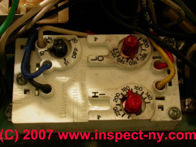
Combination control or primary control on heating boilers: this control, such as a Honeywell R8182D combine High Limit and "Low Limit" boiler controls
(The dial marked "low limit" on a combination control may or may not be in use depending on presence of a tankless coil).
This primary control, the most common type on modern heating boilers, controls the oil burner operation, turning the burner on or off as the boiler low limit or high limit temperatures are reached respectively.
This control may switch on and off a single circulator pump, and if a tankless coil is installed on the boiler, it may also turn the oil burner on and off as needed to maintain temperature in the boiler to provide domestic hot water as well.
- Combination Control High Limit: On a typical combination control, the "Hi Limit" is the cut-off temperature for the heating boiler on a call for heat. The cut-on temperature is hard wired in this control at about 15 °F below the "Hi Limit" setting.
- Combination Control Low Limit: On these
controls the "Low Limit" is NOT the "cut on" point for heat but rather it is a setting which is intended to maintain heat inside the boiler in order to
assure that the boiler can produce hot water when a tankless coil is installed.
The "Low Limit" is normally set at least 20 °F below the "Hi Limit" to avoid a "lockout" condition on this control which we discuss just below.
During warm months when the boiler is not being called-on to heat the building itself, the "Low Limit" keeps heat in the boiler for the tankless coil.
So the "Low Limit" is actually a "low range" operating upper limitOn boiler temperature that applies out of the heating season. - Combination Control Differential: On this control, the "Diff" or differential control dial specifies the amount below the "Low Limit" to which boiler temperature can
fall before the boiler should turn on to keep the boiler warm for making domestic hot water through the tankless coil.
Details about the control settings of boiler aquastats and how to set these devices to save money on heat, remain safe, and function properly, can be read
at AQUASTAT CONTROL FUNCTIONS - For a discussion about individual High Limit Switches and Low Limit Switches and controls on hot water heating boilers
see SINGLE FUNCTION LIMIT SWITCH
See AQUASTAT SELECTION GUIDE for details about the types of aquastats
See MANUALS for HEATING & A/C SYSTEM CONTROLS for a list of manuals and installation / troubleshooting guides
Backflow Preventer Valves on Heating Boilers - A Different Check Valve
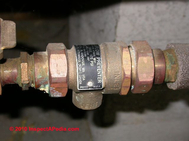
Backflow preventers are a different type of check valve found on heating systems.
The backflow preventer is installed to keep hot, high pressure water in the hydronic heating system from flowing backwards through a boiler water feed line into the building water supply - a sanitation concern.
See Check Valves Flow Control Valves Flo Control.
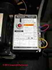
Cad Cell Relay Switches on Oil Fired Heating Boilers & Furnaces - the basics
Flame sensing devices on heating boilers: modern heating boilers using an oil burner for heat source use a Cadmium Cell sensor, usually located inside the oil burner tube, to "see" the
presence of flame and thus to assure that the oil burner assembly stops pumping oil into the combustion chamber if flame ignition is
unsuccessful.
Some older heating boilers, steam boilers, and water heaters may use a stack relay switch to confirm oil burner operation.
Heating Boiler Oil-burners use either a cad cell or stack relay to confirm that the furnace oil burner is operating properly and to avoid flooding
the combustion chamber with un-burned oil.
See CAD CELL RELAY SWITCH and
On older oil fired equipment, both boilers and furnaces,
see STACK RELAY SWITCH
- Boiler Cad Cell Relays Explained: Modern heating boilers use a Cadmium Cell sensor, usually located inside the oil burner tube, to "see" the
presence of flame and thus to assure that the oil burner assembly stops pumping oil into the combustion chamber if flame ignition is
unsuccessful.
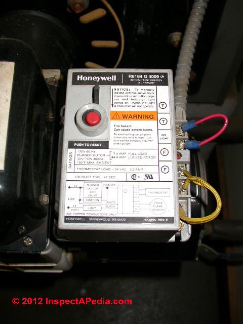
The cad cell is wired to a relay switch (usually a gray box with a red "reset" button located on top of the oil burner) which switches the oil burner off when a flame is not established in the burner. - Resetting the Oil Burner Cad Cell Relay: if the red button on the cad cell relay is sticking up and the oil burner has shut down,
the homeowner is permitted to try ONCE to "reset" the system by pressing the red reset button.
If the oil burner does not turn on and run normally and continuously (no smoke, no loud noises, etc.) for at least 5 or 10 minutes after resetting the relay or pressing the reset button, DO NOT keep resetting the system since doing so can flood the combustion chamber with un-burned heating oil - a dangerous condition. - Details about Cad Cell relay switches, how to inspect, test, and reset them can be read
at CAD CELL RELAY SWITCH
Check Valves Prevent Un-wanted Gravity or Convection Circulation of Hot Water
 If the building heating system is ON but the thermostat is NOT calling for heat, then we don't want heat to be delivered (against our wishes) to the occupied space. Specifically:
- IF electrical power switch to a hot water heating boiler is in the ON position
see ELECTRICAL POWER SWITCH FOR HEAT
- AND the room thermostat is set to "heating" mode
see details at THERMOSTATS - AND the thermostat is set below room temperature,
- THEN the heating system (hot water or steam) boiler or (warm air) furnace should not run.
And hot water should not be circulating through the building's radiators or baseboards.
So why might we be getting un-wanted heat?
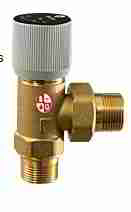
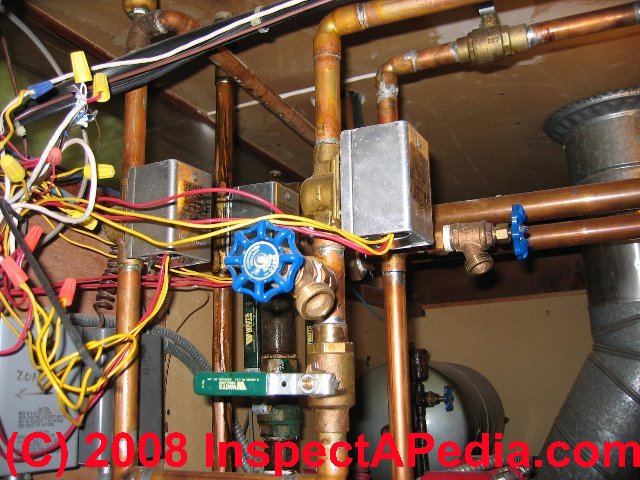
For hot water heating systems (baseboards, radiators), check valve settings (in the forced-on position) or other internal defects could cause or permit hot water to circulate through the heating system by "gravity" (convection, that is warm water rising on its own through the heating piping) even though the thermostat is not calling for heat.
The problem, if this is occurring, is usually that a check valve (photo above-left) (found internal to some circulator pumps, or external as a physical device) intended to prevent hot water from circulating on its own - when the circulator pump is off - is either set to a "forced open" position, or it has become defective.
If that's the problem (diagnosed by a heating and service technician) then the valve or circulator needs to be replaced. While waiting for that repair to be made, you can still turn off the heat, by turning off electrical power to the boiler.
See CHECK VALVES, HEATING SYSTEM for more about various kinds of check valves and flow-control or flo-control valves on heating boilers.
Circulator pumps & circulator relay switches on gas or oil fired heating boilers - the basics
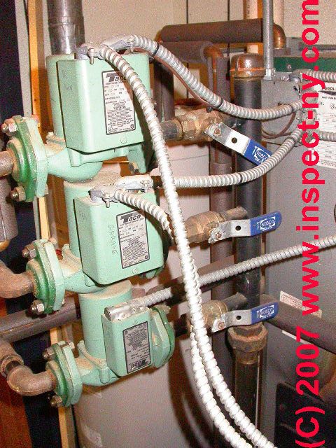
Circulator pumps & relays on heating boilers - an older and by some heating service technicians, a preferred method to control the distribution of heat to individual building areas uses a individual circulator pump to force heating water through each individual heating zone piping.
This system too is usually found
on hot water baseboard heating systems.
Two or more circulator relay switches, one relay for each circulator pump, will be installed to turn on and off
each heating water circulator if more than one heating circulator is installed.
Individual low-voltage thermostats located in the living area will respond to
a call for heat by switching on the circulator relay which in turns on the (120V) circulator pump.
Approaches to controlling heat distribution by heating zones in buildings may use
- Whole building heats as one zone using gravity or convection (no circulator pumps - an old system design usually using large-diameter piping)
- Whole building heats as one zone using a single circulator pump (forced hot water heat)
- Building heating is divided into multiple zones each controlled by an individual thermostat. Each thermostat may control
- an individual circulator pump
- an individual zone valve
- Building heating is divided into multiple zones of control each managed by an individual thermostat, while heat is distributed and controled by a mix of multiple circulators and zone valves that subdivide some of the circulator zones into smaller zones of control
Details about circulator pumps and circulator relay controls can be read
at CIRCULATOR PUMPS & RELAYS where we also provide circulator pump company contact information & circulator pump installation & repair manuals.
Details about the relays in circulator relay controls and how the relay switch works can be read
at RELAY CONTROL SWITCHES - chattering relay switches?
Differential Bypass Valves - BG
Differential bypass valves are not usually found on residential heating systems, but you may encounter one. According to B&G:
The differential bypass valve is used in systems where heating loads may be excluded from the circuit as zone valves close.
It controls the excess flow in the system by acting as a bypass while ensuring adequate flow to the remaining open circuits.
The differential bypass valve helps reduce velocity noise caused by excess flow through the circuits while maintaining the pump head at a constant value.
The differential by-pass valve should be installed after the pump between the supply and return piping.
It can be installed either in the horizontal or vertical position provided it is in accordance with the direction of flow as indicated by the arrow on the valve body.
Electrical Switches that Control Heating Systems - the basics
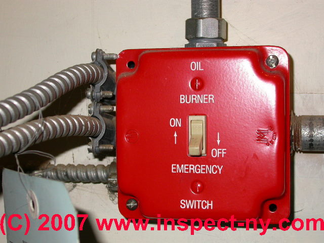
An electrical on-off switch is located out of the heating equipment room and serves to turn off electrical power to heating equipment in an emergency.
This switch should be one of the first things you check if your building has no heat, as someone may have turned it off on purpose (such as for safety reasons) or by accident.
A second electrical switch is located on or close to the heating equipment.
A third electrical switch or fuse turns off power to the heating equipment service at the building electrical panel.
See ELECTRICAL POWER SWITCH FOR HEAT where we explain these electrical switches on heating systems in more detail.
In some jurisdictions, an additional thermally-fused electrical safety switch is required at oil fired and possibly gas fired heating equipment. At below right we an older-style Fire-o-Matic fusible link electrical safety switch.
Details of this switch and its newer successors are
at FIREMATIC FUSIBLE ELECTRICAL SWITCH
Gas Fired Heating Boiler Controls
See
- GAS APPLIANCES, PIPING, CONTROLS
- GAS IGNITER DIAGNOSIS & REPAIR
- GAS PILOT WON'T STAY LIT
- GAS REGULATORS & APPLIANCE / HEATER CONTROLS
- GAS SHUTOFF VALVES, LP or NATURAL
- FLUE GAS SWITCH INSTALLATION & WIRING
- FLUE GAS SPILL SWITCH SOURCES & SELECTION
- FLUE GAS SPILL SWITCH TRIPPING & RESET
- FLUE SPILL SWITCH & COMBUSTION AIR TESTS
- THERMOCOUPLE REPAIR / REPLACEMENT
- ZONE VALVES, HEATING
Heating Thermostats & How They are Set
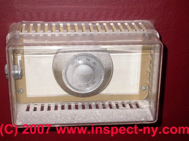
Heating & Air Conditioning Thermostats where are thermostats usually located, what types of thermostatic controls are used on various heating and cooling systems, how do we find all of the thermostats, how do we set, adjust, and use thermostats
The round Honeywell (R) wall thermostat shown in this photo has been locked in a plastic enclosure to prevent people from changing its set temperature.
Set temperature and how the thermostat works are described in excruciating detail below.
Room thermostats for air conditioning work and are set the same as when these devices are used for controlling heating systems.
We provide complete detail about how heating & cooling thermostats work, are installed, wired, diagnosed & repaired:
see THERMOSTATS for complete details.
High Limit Controls and Low Limit Controls on Heating Boilers - the basics of single limit switches
Individual High Limit and Low Limit relay switches On heating boilers: these may be provided on older heating boilers. A separate high limit control, usually mounted near the top of the heating boiler monitors boiler temperature and shuts off the oil or gas burner when that limit has been reached.
A separate low limit control (that looks like the high limit unit), usually mounted lower on the heating boiler monitors boiler temperature and turns on the oil or gas burner when the heating boiler internal water temperature reaches the low limit.
Details about individual limit switches and controls on boilers can be read
Stack Relay Controls on Oil Fired Heating Boilers & Furnaces - the Basics
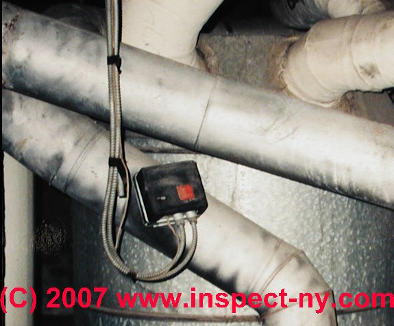
Oil Burner Stack Relay Switches Explained Older oil burners may use a Stack Relay
to accomplish the same purpose (turn off the oil burner if the flame is not established).
The "stack relay" is a bimetallic spring
inserted into the flue vent connector located usually quite close to the heating boiler between the boiler top and the chimney.
The bimetallic spring warms in response to hot oil burner exhaust, confirming that combustion is taking place.
If combustion is not
occurring a timer inside the stack relay turns off the oil burner to prevent flooding of the combustion chamber
with un-burned oil.
For details concerning this device
Low Water Cutoff Controls on Heating Boilers
Low water cutoff On steam heating boilers and on some hot water heating boilers: on both some hydronic (water) and all steam type heating boiler systems a sensor is installed on some modern heating boilers (and on virtually all steam boilers) to turn off the oil burner should the water level or pressure in the system fall below a safe level.
For details see LOW WATER CUTOFF CONTROLS and
for manuals and instructions for LWCOs
see LOW WATER CUTOFF CONTROL MANUALS
Oil Burner Primary / Safety Control Manuals
- BOILER CONTROLS & SWITCHES - controls used on all brands of heating boilers and
- FURNACE CONTROLS & SWITCHES - controls used on all brands of heating furnaces
- MANUALS & PARTS GUIDES - HVAC - home
- MANUALS for HEATING & A/C SYSTEM CONTROLS - home
- OIL BURNER MANUALS provides links to manuals for oil burners, controls, fuel units, etc.
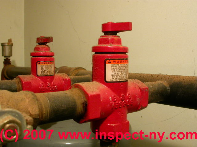
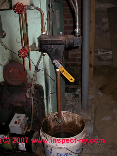
Pressure and Temperature Relief Valve on heating boilers:
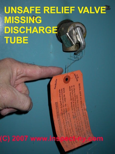 A TP valve is installed on all modern heating boilers to release hot water and pressure should
the boiler's internal pressure or temperature rise to an unsafe level.
A TP valve is installed on all modern heating boilers to release hot water and pressure should
the boiler's internal pressure or temperature rise to an unsafe level.
The relief valve should be piped to a few inches from the floor with the end of the discharge tube always in a visible location so that if it is leaking or open the building owner or manager can observe that (unsafe) condition.
Some very old heating boilers may not have a relief valve installed.
These systems used a pressure relieving overflow
tank located high in the building, above any upper floor radiators or baseboards, often in the building attic.
The attic pressure tank was open to the atmosphere and often itself included an overflow pipe which would permit any excess water (or pressure) to flow out of the tank and out of the building, perhaps through a building wall to the outdoors.
While these systems worked well for decades, placing a temperature
relief valve right on or very close to the heating boiler is a safer installation.
See RELIEF VALVE, TP VALVE, BOILER for T&P or TPR valves used on heating boilers.
See RELIEF VALVES - TP VALVES for details about all types of TPR valves.
Pressure and Temperature gauge on heating boilers: this gauge displays the heating boiler internal pressure and temperature.
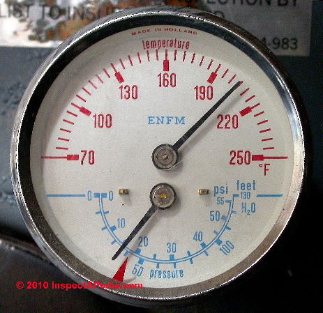 Typical pressure for a residential boiler serving a two story home would show 12 psi cold, and less than 30 psi hot. Over 30 psi boiler pressure will cause the pressure relief valve to open.
Typical hydronic heating boiler operating temperature settings are LO-120-160 HI-180-200 °F. At 200 °F. we'll see should see pressure under 30 psi.
Typical operating temperature observed at the gauge will be below the high, and can be as low as nighttime room temperature in non-heating season if no tankless coil is in use. The temperature/pressure gauge may help in checking for normal conditions before and during boiler operation.
However the boiler pressure or temperature gauge can be wrong!
See GAUGES ON HEATING EQUIPMENT for more details about pressure gauges on hydronic (hot water) heating boilers.
Pressure gauges for steam boilers are discussed
Details about gauges on steam heating equipment can be read
See GAUGES on HOT WATER BOILERS
PRESSURE GAUGE, BOILER for more details about pressure gauges on hydronic (hot water) heating boilers (these are not steam systems).
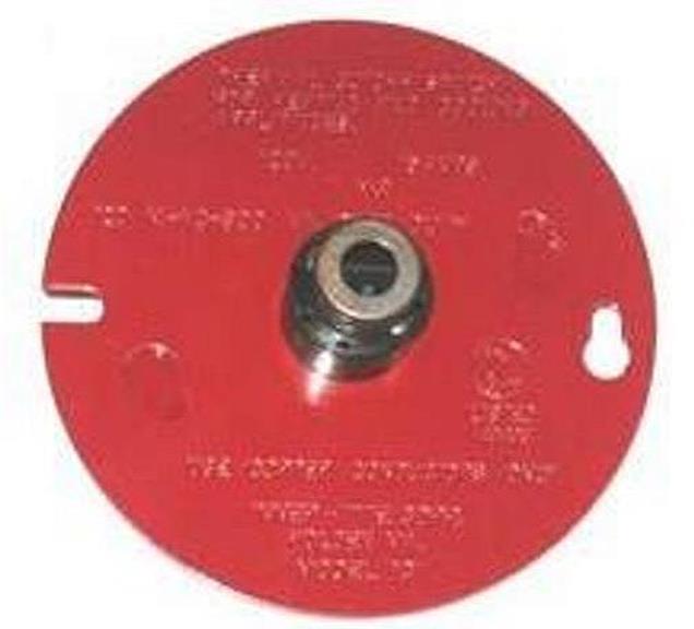
Tankless coil use on heating boilers
The tankless coil is not itself a boiler "control" but boiler controls include features to make the coil work properly.
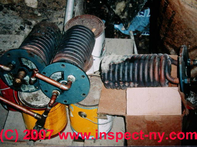
A tankless coil is basically a coil of finned copper tubing which is inserted into the heating boiler, is used to provide
domestic hot water to some buildings. Watch out for leaks at piping fittings or more seriously the coil mounting plate which bolts the coil to the
boiler (leaks at this location can destroy a steel boiler).
Watch out also for missing a mixing/tempering valve which mixes cold in with the outgoing hot water to avoid scalding temperatures
at nearby taps.
Some building jurisdictions require a separate temperature/pressure relief valve on hot water piping at the boiler.
The photo shows a pile of tankless coils found in a building basement next to the heating boiler. We suspected that high mineral content
in the building's water supply was causing frequent coil clogging.
See TANKLESS COILS for details. If you see a pile of tankless coils in a home (our photo above) you can guess that there has been a problem with hard water and tankless coil clogging - the home needs a water softener -
see WATER SOFTENERS & CONDITIONERS.
Water Feeder Valves on Hot Water and Steam Heating Systems - the basics
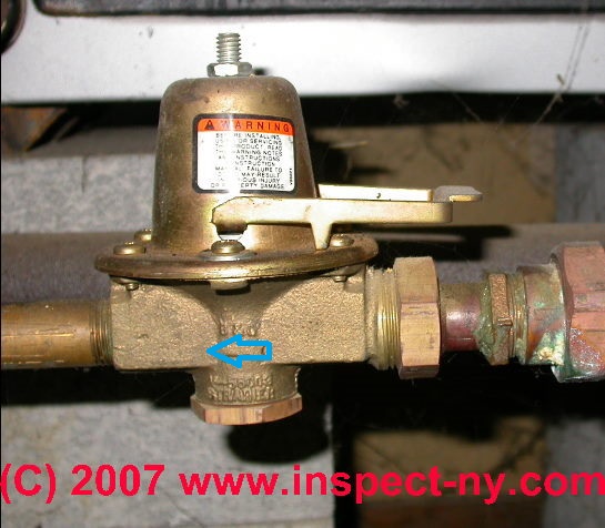
Automatic water feeder and Expansion Tank on heating boilers - these are often controlled in a single unit on modern heating boilers which use an Amtrol or similar expansion tank.
The water feeder is the brass assembly at the bottom of the expansion tank on these units.
On older heating boilers
the expansion tank and water feeder valve are separate physical units. On these older systems the "automatic water feeder" is often a
bell-shaped device which opens and sends makeup water into the heating boiler and its piping whenever the heating system's internal
water pressure falls below a normal level (perhaps 12 psi when the boiler is cold).
Some older heating systems may not have an automatic
water feeder and may only provide a manually operated valve to add water to the boiler.
Systems without an automatic water feeder are less safe and risk serious boiler damage should boiler water be lost and should there be no low water cutoff installed on the system.
See WATER FEEDER VALVES for details about water feed valves for hydronic boilers.
Steam boiler automatic water feed valves are discussed
Zone Valves on Hot Water Heating Systems - the basics
Zone valves on heating boilers - heating water piping in a building, particularly where hot water baseboard heat is used, may be divided into separate heating zones (different floors, or different areas on a single floor) to permit more detailed control of heat distribution in a building.
The control of heating water through these different heating zones may be accomplished
by use of zone valves (one per heating zone or area or "loop" of heating piping) which in turn are connected to individual thermostats.
When the thermostat calls for heat in a particular building area, the thermostat switch causes the zone valve to open, to permit hot water to flow through that zone.
When the zone valve is fully open, an "end switch" inside the valve tells the heating system's circulator to begin operating, causing hot water to flow
through the zone.
Typically heating systems using zone valves will have two or more zone valves (usually but not always located close to the heating
boiler) and a single circulator pump (usually located on the return end of the hot water piping close to the heating boiler).
Details about zone valves on hot water heating systems can be read
Reader Comments, Questions & Answers About The Article Above
Below you will find questions and answers previously posted on this page at its page bottom reader comment box.
Reader Q&A - also see RECOMMENDED ARTICLES & FAQs
On 2021-02-03 - by (mod) -
Louis I wish I could help but setting an automatic call number is device and service specific. You'll want to identify the service to which you're subscribed and give them a call.
On 2021-02-01 by Louis
I have a auto call if there is any problem How can I change the phone number on the auto call
On 2020-03-01 by (mod) - Running furnace little heat
Anon if your heat is by forced hot water (hot water baseboards, radiators, convectors) then your heater is a "boiler" and the most-common cause of a boiler that runs while not heating the home will be found by searching this site or looking in
the ARTICLE INDEX (above) for AIR BOUND HEATING SYSTEMS
If your heat is by forced hot-air or "warm air heating system" then start
at DIAGNOSE & FIX FURNACE PROBLEMS
On 2020-03-01 by Anonymous
Running furnace little heat
On 2019-11-25 - by (mod) -
Clayton
Use the search box just above to find our diagnostic article titled HEAT WON'T TURN OFF to see the probable cause (such as a zone valve or check valve stuck open)
On 2019-11-22 by clayton
I have hot water heat and one zone will not stop heating even with the thermostat disconnected
On 2019-02-06 - by (mod) -
Anna
Do not keep pressing the reset button - you risk a dangerous PUFFBACK EXPLOSION - instead, call your heating company to repair, or clean and service the system to get it running reliably.
On 2019-01-20 by Anna
I have a Columbia oil boiler and the boiler goes on for a few minute then it goes off and I have to keep hitting the red button to turn it back on but the boiler only stays on for a few minute. There's oil in the tank.
...
Continue reading at AIR BLEEDER VALVES or select a topic from the closely-related articles below, or see the complete ARTICLE INDEX.
Or see BOILER CONTROL & SWITCH FAQs - questions and answers about heating boiler controls & switches, posted originally on this page.
Or see these
Recommended Articles
- BOILERS, HEATING - home
- BOILER CONTROLS & SWITCHES
- AIR BLEEDER VALVES
- AIR SCOOPS PURGERS SEPARATORS
- AQUASTAT CONTROLS
- BACKFLOW PREVENTER VALVE, HEATING
- BOILER PRESSURE CONTROLS & SETTINGS
- CAD CELL RELAY SWITCH
- CHECK VALVES, HEATING SYSTEM
- CIRCULATOR PUMPS & RELAYS
- ELECTRICAL POWER SWITCH FOR HEAT
- EXPANSION TANKS
- FIRE SAFETY CONTROLS
- GAS REGULATORS & APPLIANCE / HEATER CONTROLS
- GAUGES, HYDRONIC BOILER
- LIMIT SWITCH, BOILER
- LOW WATER CUTOFF VALVE, BOILER
- MIXING / ANTI-SCALD VALVES
- OIL LINE QUICK STOP VALVES
- OIL SUPPLY LINE SAFETY VALVES, OSVs
- PRESSURE & TEMPERATURE SETTINGS, CONTROLS
- RESET SWITCH, PRIMARY CONTROL
- RESET SWITCH, ELECTRIC MOTOR
- FLUE GAS SWITCH INSTALLATION & WIRING
- FLUE GAS SPILL SWITCH SOURCES & SELECTION
- FLUE GAS SPILL SWITCH TRIPPING & RESET
- FLUE SPILL SWITCH & COMBUSTION AIR TESTS
- STACK RELAY SWITCH
- THERMOCOUPLE REPAIR / REPLACEMENT
- ZONE VALVES, HEATING
- MANUALS & PARTS GUIDES - HVAC - home - Master Index to All Brand Names & HVAC manuals, wiring diagrams, installation and repair guides
- OIL BURNER MANUALS
- MANUALS for HEATING & A/C SYSTEM CONTROLS
- STEAM HEATING SYSTEMS & CONTROLS - home
Suggested citation for this web page
BOILER CONTROLS & SWITCHES at InspectApedia.com - online encyclopedia of building & environmental inspection, testing, diagnosis, repair, & problem prevention advice.
Or see this
INDEX to RELATED ARTICLES: ARTICLE INDEX to HEATING BOILERS
Or use the SEARCH BOX found below to Ask a Question or Search InspectApedia
Ask a Question or Search InspectApedia
Try the search box just below, or if you prefer, post a question or comment in the Comments box below and we will respond promptly.
Search the InspectApedia website
Note: appearance of your Comment below may be delayed: if your comment contains an image, photograph, web link, or text that looks to the software as if it might be a web link, your posting will appear after it has been approved by a moderator. Apologies for the delay.
Only one image can be added per comment but you can post as many comments, and therefore images, as you like.
You will not receive a notification when a response to your question has been posted.
Please bookmark this page to make it easy for you to check back for our response.
Our Comment Box is provided by Countable Web Productions countable.ca
Citations & References
In addition to any citations in the article above, a full list is available on request.
- Bell & Gossett Air Separators and other heating system components, Bell & Gossett, 8200 N. Austin Ave., Morton Grove IL 60053, USA - Tel 847 966-3700 Fax 847 965-8379.
- Thanks to Bottini Fuel service manager Ron Thomas for discussing aquastat functions, low limit controls, oil burner short cycling causes, and boiler maintenance, reliability, and service contracts 4/13/2010. Bottini Fuel is a residential and commercial heating oil distributor and oil heat service company in Wappingers Falls, NY and with offices in other New York location
- Domestic and Commercial Oil Burners, Charles H. Burkhardt, McGraw Hill Book Company, New York 3rd Ed 1969.
- National Fuel Gas Code (Z223.1) $16.00 and National Fuel Gas Code Handbook (Z223.2) $47.00 American Gas Association (A.G.A.), 1515 Wilson Boulevard, Arlington, VA 22209 also available from National Fire Protection Association, Batterymarch Park, Quincy, MA 02269. Fundamentals of Gas Appliance Venting and Ventilation, 1985, American Gas Association Laboratories, Engineering Services Department. American Gas Association, 1515 Wilson Boulevard, Arlington, VA 22209. Catalog #XHO585. Reprinted 1989.
- The Steam Book, 1984, Training and Education Department, Fluid Handling Division, ITT [probably out of print, possibly available from several home inspection supply companies] Fuel Oil and Oil Heat Magazine, October 1990, offers an update,
- Principles of Steam Heating, $13.25 includes postage. Fuel oil & Oil Heat Magazine, 389 Passaic Ave., Fairfield, NJ 07004.
- The Lost Art of Steam Heating, Dan Holohan, 516-579-3046 FAX
- Principles of Steam Heating, Dan Holohan, technical editor of Fuel Oil and Oil Heat magazine, 389 Passaic Ave., Fairfield, NJ 07004 ($12.+1.25 postage/handling).
- "Residential Steam Heating Systems", Instructional Technologies Institute, Inc., 145 "D" Grassy Plain St., Bethel, CT 06801 800/227-1663 [home inspection training material] 1987
- "Residential Hydronic (circulating hot water) Heating Systems", Instructional Technologies Institute, Inc., 145 "D" Grassy Plain St., Bethel, CT 06801 800/227-1663 [home inspection training material] 1987
- "Warm Air Heating Systems". Instructional Technologies Institute, Inc., 145 "D" Grassy Plain St., Bethel, CT 06801 800/227-1663 [home inspection training material] 1987
- Heating, Ventilating, and Air Conditioning Volume I, Heating Fundamentals,
- Boilers, Boiler Conversions, James E. Brumbaugh, ISBN 0-672-23389-4 (v. 1) Volume II, Oil, Gas, and Coal Burners, Controls, Ducts, Piping, Valves, James E. Brumbaugh, ISBN 0-672-23390-7 (v. 2) Volume III, Radiant Heating, Water Heaters, Ventilation, Air Conditioning, Heat Pumps, Air Cleaners, James E. Brumbaugh, ISBN 0-672-23383-5 (v. 3) or ISBN 0-672-23380-0 (set) Special Sales Director, Macmillan Publishing Co., 866 Third Ave., New York, NY 10022. Macmillan Publishing Co., NY
- Installation Guide for Residential Hydronic Heating Systems
- Installation Guide #200, The Hydronics Institute, 35 Russo Place, Berkeley Heights, NJ 07922
- The ABC's of Retention Head Oil Burners, National Association of Oil Heat Service Managers, TM 115, National Old Timers' Association of the Energy Industry, PO Box 168, Mineola, NY 11501. (Excellent tips on spotting problems on oil-fired heating equipment. Booklet.)
- Weil McLain Model 78 Boiler Manual, Boiler for gas, light oil, Gas/Light Oil fired Burners, Installation, Start-up, Parts, Maintenance instructions, Part No. 550-141-705/0600, Weil-McLain Administrative Office, 999 McClintock Drive, Suite 200, Burr Ridge, IL 60527
Tel: 855-248-1777
Consumer Inquiries: 800-368-2492
Technical Services: 800-526-6636 Technical Support for Contractors Only.
If you are a homeowner and are experiencing a problem with your Weil-McLain equipment, the first step you must take is to contact your installer or locate an HVAC contractor in your area. Website: http://www.weil-mclain.com - Our recommended books about building & mechanical systems design, inspection, problem diagnosis, and repair, and about indoor environment and IAQ testing, diagnosis, and cleanup are at the InspectAPedia Bookstore. Also see our Book Reviews - InspectAPedia.
- In addition to citations & references found in this article, see the research citations given at the end of the related articles found at our suggested
CONTINUE READING or RECOMMENDED ARTICLES.
- Carson, Dunlop & Associates Ltd., 120 Carlton Street Suite 407, Toronto ON M5A 4K2. Tel: (416) 964-9415 1-800-268-7070 Email: info@carsondunlop.com. Alan Carson is a past president of ASHI, the American Society of Home Inspectors.
Thanks to Alan Carson and Bob Dunlop, for permission for InspectAPedia to use text excerpts from The HOME REFERENCE BOOK - the Encyclopedia of Homes and to use illustrations from The ILLUSTRATED HOME .
Carson Dunlop Associates provides extensive home inspection education and report writing material. In gratitude we provide links to tsome Carson Dunlop Associates products and services.
 | HOME | ABOUT | ASK a QUESTION | CONTACT | CONTENT USE POLICY | DESCRIPTION | POLICIES | PRIVACY | |
| © 2024 - 1985 Publisher InspectApedia.com - Daniel Friedman | |||||||||