
InspectAPedia® FREE Encyclopedia of Building & Environmental Construction, Diagnosis, Maintenance & Repair |
Question? Just ask us! InspectAPedia
|
 Guide to Barometric Dampers & Draft Regulators
on Oil Fired Heating Equipment, Wood Stoves, Coal Stoves
- POST a QUESTION or COMMENT about draft regulators and barometric dampers on both gas & oil fired heating equipment & about inspecting and adjusting the barometric damper or draft regulator on oil fired heating equipment
Draft regulators / barometric dampers on oil fired heating equipment:
Here we explain the inspection and adjustment of draft regulators or barometric dampers on oil fired heating equipment:
A Guide to Barometric Dampers on Oil Fired Boilers, Furnaces, Water Heaters: inspection, adjustment, cleaning, troubleshooting.
InspectAPedia tolerates no conflicts of interest. We have no relationship with advertisers, products, or services discussed at this website.
Guide to Inspecting Barometric Dampers or Draft Regulators on Oil Fired Heaters, Furnaces, Boilers, Water Heaters
 [Click to enlarge any image]
Article Series Contents
- AUTOMATIC VENT DAMPERS
- CHIMNEY DRAFT & PERFORMANCE
- DRAFT REGULATOR, DAMPER, BOOSTER
- DEFINITION of BAROMETRIC DAMPER / DRAFT REGULATOR
- DRAFT REGULATOR PURPOSE
- DRAFT REGULATOR ADJUSTMENT & SETTINGS
- DRAFT REGULATOR INSPECTION
- DRAFT REGULATOR LOCATION
- DRAFT REGULTOR OPERATION
- GAS HEATER DRAFT REGULATION
- LOOSE or DAMAGED DRAFT REGULATORS
- SIZES of DRAFT REGULATORS
- SOOT at the DRAFT REGULATOR
- DAMPERS & DRAFT REGULATOR TYPES
- DRAFT REGULATORS / HOODS GAS HEATERS
- DRAFT INDUCER FANS
- DRAFT MEASUREMENT, CHIMNEYS & FLUES
- DRAFT REGULATOR SOOT INSPECTION
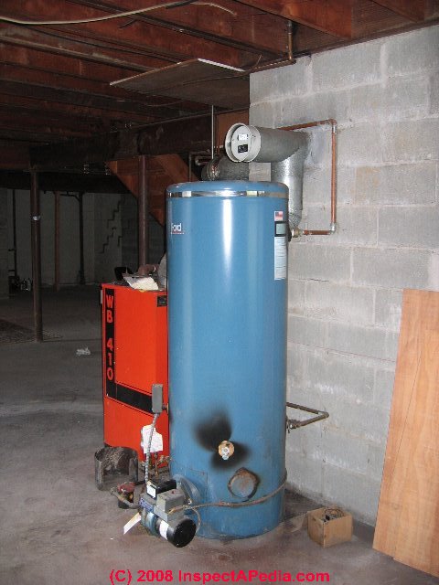
Draft Regulators for oil fired heaters: Details about draft control on oil fired heating systems (such as the oil fired heater shown in the photo above), including furnaces or boilers, are discussed in this article just below.
Draft Regulators for gas fired heaters: Details about draft control for gas fired heating systems, including furnaces or boilers, are discussed separately at
at DRAFT REGULATORS / HOODS GAS HEATERS for gas fired equipment.
Define Barometric Damper or Draft Regulator
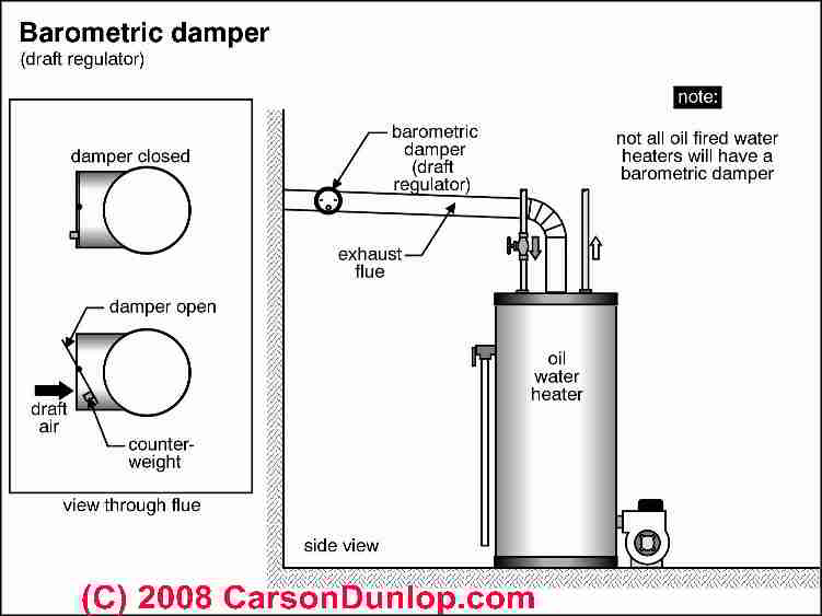
Barometric dampers are devices used to regulate the draft on oil-fired heating equipment such as furnaces, boilers, or water heaters. The barometric damper or draft regulating device we are discussing here is normally used only on oil-fired heating equipment, not on gas-fired equipment.
On oil fired equipment the barometric damper, or draft regulator is typically a round Tee inserted in the flue vent connector between the heating appliance and the chimney. The face of the tee contains a round "door" with an adjustable weight.
The service technician adjusts the weight to control the swing or opening of this door which in turn controls the amount of excess air that can enter the flue and chimney when the oil burner is operating.
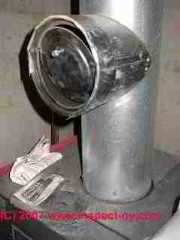
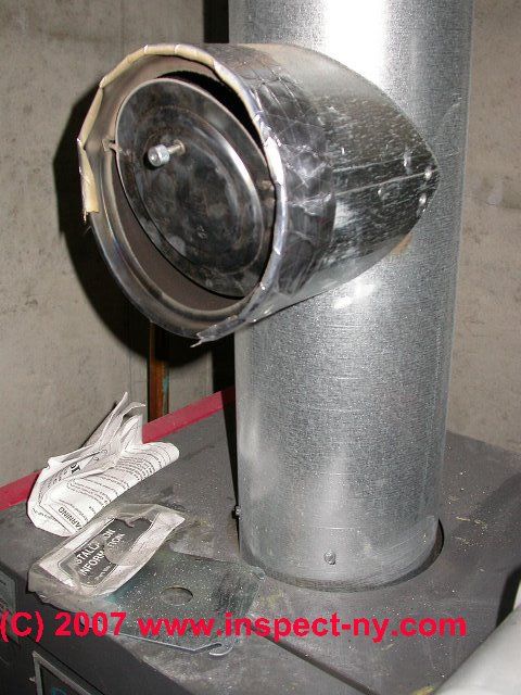
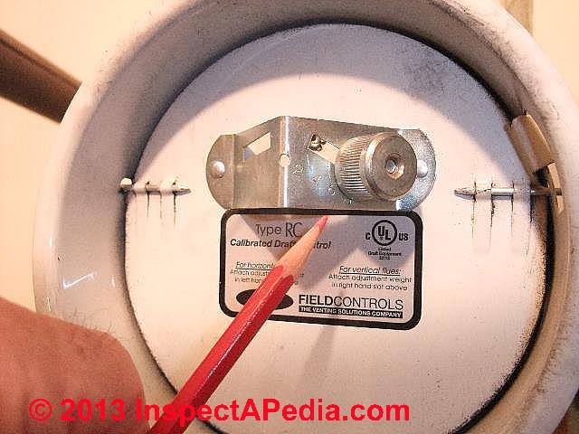
The draft regulator in our photo shown just above is not working - and has been deliberately jammed - indicating that something else is wrong, probably a chimney problem or an oil burner operating problem: the technician was unable to get enough draft, so s/he defeated the regulator - this is not a good idea, as we'll explain below.
Why we need the Barometric Damper or Draft Regulator on a Boiler or Furnace
During oil burner operation, and also on some gas fired equipment, combustion air moves into the burner are and combustion chamber (as combustion air).
As combustion continues (the fuel is mixed with air and burned), a mix of air and combustion gases continues onwards, moving out of the combustion chamber, up through the boiler or furnace heat exchanger, through the flue vent connector ("stack pipe or flue pipe" and on into the chimney where these gases are finally vented outside, usually above the building roof.
The force with which this air or combustion gas moves is the "draft" inside of the heating appliance.
Too much draft increases heating appliance operating cost by venting heat out through the chimney instead of transferring the heat into the building where it was wanted. Too much draft can also increase chimney temperatures to an unsafe level.
Too little draft can result in incomplete combustion, soot-clogging of heating equipment (dangerous), and more dangerous heating appliance malfunctions such as oil burner puffbacks and in some cases dangerous production of carbon monoxide gas that leaks into the building (a potentially fatal problem).
So virtually all fossil-fuel-fired heating appliances provide some sort of draft control or draft regulator to keep the draft at required levels both in the combustion chamber and out through the chimney.
Details of Why is a draft regulator is needed ?
Chimney draft is not constant.
While above we described how we measure draft inside of heating equipment and on the way to the chimney where (we hope) combustion gases are to be vented safely outside, the "draft" that the oil burner and furnace or boiler experience are not constant.
For example wind blowing over a chimney top can increase draft, as can a second appliance using the same chimney as the heater. Since the force of draft is not normally constant, and since we want the draft to be constant for optimum oil burner operation, the barometric damper is installed.
If the oil burner sees flue draft that is too low
the combustion gases will not vent safely out of the building and the heating equipment may suffer from backpressure in the combustion chamber, causing overheating or other malfunctions.
Also see OIL BURNERS
and OIL BURNER NOISE SMOKE ODORS
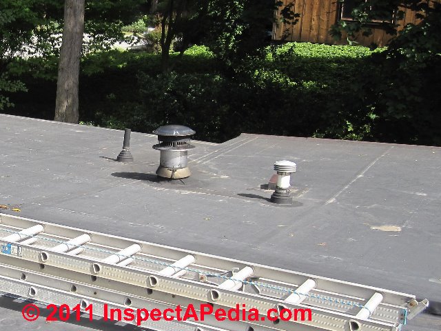
Our photo (above left) shows a chimney that extends less than two feet above a flat roof on a one story home, resulting in inadequate draft and sooty burner operation.
The home suffered recurrent oil burner sooting, puffbacks, high and repeated heating service repair bills, and ineffective attempts by heating service techs to "fix" the problem by running the oil burner at high temperatures - a trick that mostly served to increase the heating bills for the home.
At DRAFT MEASUREMENT, CHIMNEYS & FLUES we illustrate how this particular short chimney and inadequate draft problem were finally fixed.
If you have this problem
Also see DRAFT INDUCER FANS.
If the oil burner sees flue draft that is too high
combustion gases will vent out of the building just fine, but we're sending too much heat up the chimney by moving combustion gases too fast through the heater, thus we're sending our oil dollars up the chimney as heat rather than into the building as heat.
The service technician adjusts the barometric damper to maintain a continuous draft in the range we described above. Then if local conditions change, the barometric damper can open or close to let in more or less additional air into the flue and chimney, keeping the draft constant.
Are Barometric Draft Controls Used on Gas-Fired Equipment?
Draft controls are found on gas-fired heating equipment too, but the specifications are quite different.
Gas fired heaters such as domestic gas fired furnaces are usually designed to operate at very low over-fire drafts - which means almost zero draft will be measured at the flue vent connections.
That's why you usually don't see a hinged-door barometric draft regulator on gas fired equipment.
Details about draft regulators for gas fired heating equipment are found in our separate article
at DRAFT REGULATORS / HOODS GAS HEATERS
for details.
Field Corporation [1], and Tjernlund [2] draft regulator producers, provides different model draft controls for gas fired equipment, such as the Field Type MG1 and MG + MG2 regulators which use double swinging gates that open inward under normal up-draft conditions and outward in case of blocked flues, thus relieving internal pressures.
Since improper venting of gas fired appliances easily produces very dangerous, potentially fatal Carbon Monoxide (CO), it is critical that these appliances are vented properly.
Watch out: Do not ever install an oil-fired appliance draft regulator such as the Field Type AF shown here onto gas-fired equipment.
Where Should the Draft Regulator (Barometric Damper) be Installed?
Barometric damper location:
a barometric damper will work properly to regulate draft and reduce backdrafts in a variety of locations in relation to the heating appliance and the chimney. [Images at left are courtesy Field Controls cited at the end of this article.]
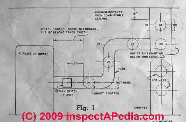
Field corporation and other equipment manufacturers provide an instruction sheet with their product, showing the appropriate locations for a draft regulator. According to Field,
"The control should be located as close as possible to a furnace or boiler and positioned as shown in [the figure at left]. The draft regulator should be 18" from a stack switch and at least 18" from a combustible ceiling or wall. Do not locate the draft regulator in a room separated from the appliance." [1]
If the draft regulator is not located properly it won't work properly and the heating system may also be unsafe. Further, if you see a draft regulator installed at the far end of a very long flue vent connector, say 12 to 25 feet or more, there is a more basic problem with excessive flue length and operating problems related to that condition, independent of the draft regulator.
See FLUE VENT CONNECTORS for details.
"The barometric damper should be adjusted (by adjusting the weight position) to maintain as low a draft as will give good combustion and meet the requirements for heat.
The bracket is marked "Lo", "Med" and "Hi" which correspond to draft settings [if draft is measured inside the flue immediately before the regulator] of 0.2", 0.4", and 0.6" w.c."
Measure Chimney & Flue Draft when adjusting the barometric damper / draft regulator
Details about when, where, how and why to measure draft at oil or gas fired heating equipment as well as measuring draft for fireplaces, coal stoves, wood stoves etc. are
at DRAFT MEASUREMENT, CHIMNEYS & FLUES.
Excerpts on typical draft settings or targets for oil fired heating equipment are given just below.
Normally we measure draft at two locations: over the fire or in the combustion chamber. The draft we typically see on oil fired heating equipment like water heaters, boilers and heating furnaces is
- - 0.02" to 0.03" water column (w.c.) in the combustion chamber just over the fire
- - 0.04" to 0.06" w.c. in the breech - the flue pipe area between the top of the boiler and the bottom of the barometric damper. Some oil burner models require higher draft than these numbers, and other oil burner models are actually tolerant of back-pressure in the combustion chamber (positive draft, or draft in the "wrong" direction").
The sketch at left showing a barometric damper on oil fired heating equipment (heating boilers or water heaters) was provided courtesy of Carson Dunlop Associates, a Toronto home inspection, education & report writing tool company [ carsondunlop.com ].
In the breech we want to see about -0.05 inches WC pressure. If the breech draft is too low the combustion process and venting process may be inadequate, and if the draft measured in the breech is lower than the draft measured over the fire, the oil burner and combustion chamber are operating under pressure - which is often a problem on residential heating systems since few of them are designed to work this way. Thanks to L. - for correcting our WC pressure data.
How Does a Barometric Draft Control or Draft Regulator Work?
It's easy to understand how a draft regulator work: as Carson Dunlop's sketch above shows.
The service technician measures draft over the fire and in the breech, and she moves a little weight on the hinged barometric damper door to cause the door to open wider or less wide to let more or less room air into the chimney as needed.
As long as the gas pressure inside of the flue and chimney is less than room air (that is, it's "negative" as we explained below), air from the room wants to enter the chimney through the barometric damper opening. Like the porridge in Goldilocks and the Three Bears, there are three possibilities:
The draft as sensed at the barometric damper is too strong
(maybe a wind is blowing over the chimney top, increasing the draft): in this case the draft inside the flue, at the breech at the draft regulator is more negative - maybe -1.2 " w.c..
Since the air in the room is at normal pressure it will be stronger than the pressure inside the flue, so air in the room will push the draft regulator door "in" and make it open, letting room air flow into the chimney until, balanced by the setting of the weight on the moving draft regulator's door, the incoming room air enters the flue in enough volume to drop the draft pressure back to its desired setting, maybe to -0.04" w.c.
The draft as sensed at the barometric damper is too weak
(maybe a wind is blowing down the chimney flue because we left off our chimney cap): in this case the draft inside the flue, at the breech and thus at the draft regulator is less negative, maybe -0.01" w.c. than we wanted - we're having trouble sending those flue gases up the chimney.
The little weight on the draft regulator door causes the door to close, reducing the inflow of room air into the flue, and thus increasing the draft in the flue back to the desired number, maybe to -0.04" w.c. once again.
The draft as sensed at the barometric damper is just right: it's hovering where we set it at -0.04" w.c. In this case the barometric draft regulator is probably showing its little door a little bit open, with a little room air flowing into the flue. (Otherwise we wouldn't have any room to close the door to increase the draft when we need to do so.) And the draft in the flue is staying at the desired number, maybe -0.04" w.c.
How is the Barometric Draft Control Adjusted? What are the recommended draft settings?
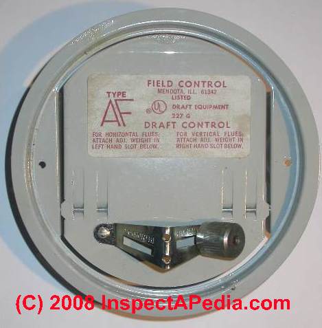 By moving a weight along a scale. You can see a weight and scale in our photo of the Field Type AF Draft Control.
In general the draft regulator is set to the lowest draft that gives good combustion and proper oil burner operation. Higher wastes energy.
While the heating equipment is operating at normal temperature, the draft is set to a number specified by the oil burner manufacturer, so we can only give approximate settings in this discussion. To find the proper weight setting to control the draft regulator, the heating service technician will make three measurements:
- Draft over the fire
(typically set to 0.02" to 0.03" WC over the fire) - Draft in the breech
(always higher than the draft over the fire, and typically around 0.04 - 0.06" WC). - CO2 measurements
(which tells us how complete is the heating oil combustion process) - adjusting the draft affects the rate of combustion air movement into the combustion chamber. - Stack temperature measurements
made at any heating appliance give another indication of system operating efficiency and proper draft settings.
A fire that is too hot, measured in the breech or flue vent connector is sending too much heat up the chimney rather than into the building, while a temperature that is too low risks fouling the equipment.
And very high stack temperatures also indicate a fire or safety hazard. Typical stack temperatures for oil fired heating equipment will be around 450 °F.
And for burning dry wood in a wood stove, 350-450 °F.
Proper coal stove operating temperatures vary by appliance and are specified by the manufacturer. Improper temperatures may also be an indicator of dangerous, potentially fatal carbon monoxide production.
It is the position of the weight along a moveable scale,
usually by screwing the weight in or out, or by sliding the weight along a scale (see our photo), that adjusts how far the draft regulator door will open in response to these three conditions described above. It's basically a principle of leverage -the weight is moved closer to or farther out from the axis of rotation of the moving draft regulator door.
When the barometric draft regulator door is more open,
it is admitting more building air into the flue and reducing the draft seen by the heating appliance. When the draft regulator door is more closed, it is admitting less building air into the flue and is thus increasing the draft seen by the heating appliance.
So do not change the barometric draft control's weight setting
unless you're a trained service technician who knows when, where, how, and why to measure draft at an oil fired heating appliance.
Weight location & adjustment on barometric draft controls
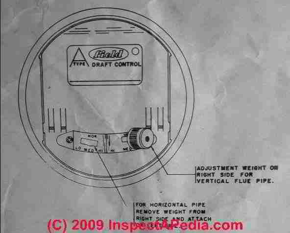
Weight location & adjustment on barometric draft controls:
the weight that is adjusted to regulate the operation of the draft control needs to be properly located as well as adjusted. T
he weight location switches on most regulators depending on whether the regulator is installed on a vertical flue or a horizontal flue. Field ships their draft regulators with the weight installed in position for a vertical flue.
The adjustment weight is in the right-hand slot when you are facing the control. If the damper is to be installed on a horizontal flue, the weight must be removed from the right-hand slot and attached to the left hand slot as shown in the illustration and sketches above.
Thanks to boiler expert Dirk Faegre for suggesting these additional details.
Why we Measure Carbon Dioxide CO2 as Well as Draft when Adjusting the Draft Regulator
Field controls also points out that
It is essential that CO2 readings be taken to determine proper [draft regulator] adjustments. (This test and others should be conducted by a qualified fuel oil dealer or appliance installer for your safety). [1]
While we and the draft regulator manufacturers give typical draft measurement numbers for draft over the fire and at the damper itself, some oil burner manufacturers may require specific draft settings other than those standard ones.
In addition, variations in chimney and building details from one installation to another may affect how the oil burner, heating appliance itself, flue vent connector, chimney, chimney cap, and site wind conditions all interact. Ultimately we need to know these effects on combustion. We want not only proper draft and [usually] no backpressure in the combustion chamber, we also want efficient combustion - that's where the CO2 measurement comes in.
Draft Regulator Inspection Points, List of Defects & Signs of trouble with a barometric damper or draft regulator and what they mean

For a detailed guide to inspecting draft regulators and barometric dampers and for example of additional draft regulator defects, failures, mis-adjustment, please
see DRAFT REGULATOR SOOT INSPECTION.
- No draft regulator or barometric damper is installed:
in this case the heater may work but it is impossible to tune it for optimum performance. We may be wasting fuel and money. - The barometric damper is shared:
if the damper is connected so that it is shared by two different heaters, say an oil fired furnace and an oil fired water heater, it is impossible to tune the system for optimum performance since the two appliances will prefer different adjustments each. - The draft regulator is in the wrong location:
too far away from the appliance it serves. The barometric damper is to be located as close to the heating appliance it serves as possible, but at least 18" away from a smoke stack control if one is also in use at the heater (such as at a wood stove).[4]
Details are
- at DRAFT REGULATOR (Barometric Damper) INSTALLATION LOCATION
- The draft control (damper assembly) is mounted out of level.
As Field Controls points out
Damper must be mounted with the hinge pins horizontal and the face of the damper plumb for correct operation. [3 - Barometric Draft Control Model B-34]
In all barometric damper (draft regulator) installations, the face of the draft control must be plumb and the hinge or bearing surfaces must be level regardless of whether the draft control itself is mounted on a vertical, horizontal, or sloping flue vent connector pipe. - The draft control is mounted upside down? Really?
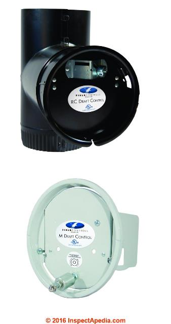
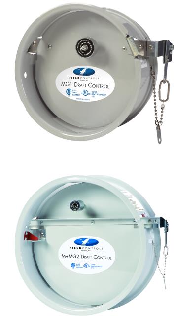
Notice that as illustrated in the two images of draft controls from Field Controls in our first photo above, the weight may be positioned "up" or "down" depending on the draft control model.
The RC draft control (designed for oil or coal heaters) has the weight and hinge "up".
The Model M draft regulator is shown with the adjustable weight "down". For draft controls whose hinge is in the lower third of the opening (the lower control in our image), it's might appear that this control will work properly only as shown - with the weight at the bottom of the control door. That's not so. The Field MG1 and MG2 Draft Controls have the hinge in the upper third of the opening and the weight above the hinge.
But our second illustration above shows two different Field Draft Controllers both of which have the hinge in the upper third of the opening and the adjustable weight is above the hinge.
Some draft controllers work with the weight above or below the hinge, but be sure to check the installation manual for your specific draft regulator as well as to measure the draft to adjust it properly for the fuel and burner type and chimney properties at your installation. With no other information such as an "up" arrow embossed on the draft regulator, I would install it with the label and writing properly oriented "up".
All of the draft regulator manufacturers provide installation instructions - look in the box in which your product came. If your draft regulator is a Field Controls device, the company provides installation guides for each draft regulator at the company's website but they can be tricky to find. Use this link http://www.fieldcontrols.com/reference-guides and enter the draft regulator model number such as MG1.
- The barometric damper is broken, has loose or missing parts:
it cannot do its job and needs repair or replacement. Required parts include necessary mounting & securing screws for the draft regulator collar, flue vent connector or tee, and the draft regulator itself where it mounts into the collar or tee. Additional details about loose or falling-off draft regulator (barometric damper) parts are below
at LOOSE or DAMAGED DRAFT REGULATOR - The barometric damper is stuck or has been wired shut or covered
with foil or tape: we love this clue. This is what a service tech does when s/he simply has been unable to get adequate draft for the oil burner. The tech thinks that since draft is always inadequate on this system there is no reason to let any air in at the damper.
Well that's true, but we're treating the symptom, not the cause. T
he root cause might be, for example, a blocked chimney flue - which is unsafe and needs to be discovered and cleared, or a chimney that is simply too short in its total height to ever develop adequate draft.
We've also see this silly "repair" when the underlying problem leading to inadequate draft was that someone had left the cleanout door to the chimney open. - The barometric damper is stuck in the "open" position -
usually due to a mechanical defect that is easily repaired, but sometimes because the weight has been misadjusted or lost. An always-open damper cannot properly regulate draft. - The barometric damper has not been properly adjusted or system draft has never been measured.
Just installing a barometric damper without adjusting it to the requirements of the heater, chimney and site is an inadequate job.
Field Controls points out, for oil fired heating appliances the system cannot be properly adjusted "by eye".:
Proper operation of the regulator depends upon proper installation and adjustment. Use a CO2 indicator, stack thermometer and draft gauge to adjust draft for oil fired burners. Domestic oil burners work best with the draft over fire of .01 to .02-inches W.C. [4]
But for wood or coal burning heaters, the company does offer alternative (to instrument-based) draft regulator adjustment procedures:
[For wood or coal burning heaters] If a draft gauge is not available, with the draft regulator fully installed and a good fire burning, adjust the counterbalance weight closer to the gate for as low a draft setting as possible, without the fire dying or getting smoke-back with the stove door slightly open. To obtain higher heat levels, move the weight away from the gate to increase the setting.[3]
Details are discussed in the article above
at DRAFT REGULATOR ADJUSTMENT & SETTINGS
and draft measurement is detailed as a procedure
at DRAFT MEASUREMENT, CHIMNEYS & FLUES - The counter-balance weight assembly is missing,
damaged, incomplete, modified. - The barometric damper is not properly secured -
discussed just below at Loose or Damaged Draft Regulators - The barometric damper collar length is too short or too long.
Field Controls points out that a mounting collar length that is too short or too long can interfere with the effectiveness of the draft control device. Correct collar lengths range from about 4 3/8" (a 10-inch control) to 15 3/4" (for a 32-inch diameter draft controller).[5]
Loose or Damaged Draft Regulator (Barometric Damper) Parts or Improper Draft Regulator Installation Points
Field-installed draft regulator tee vs. using a factory tee
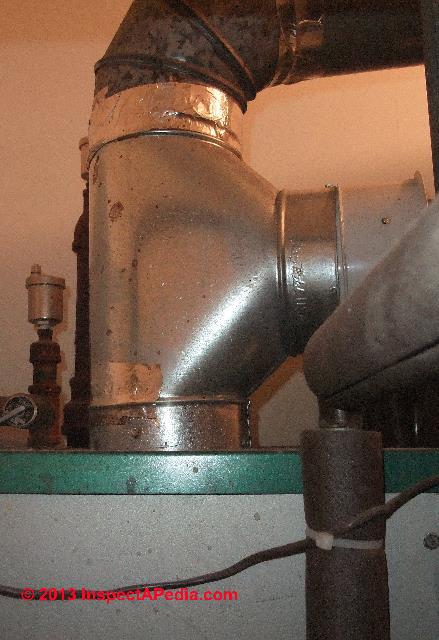
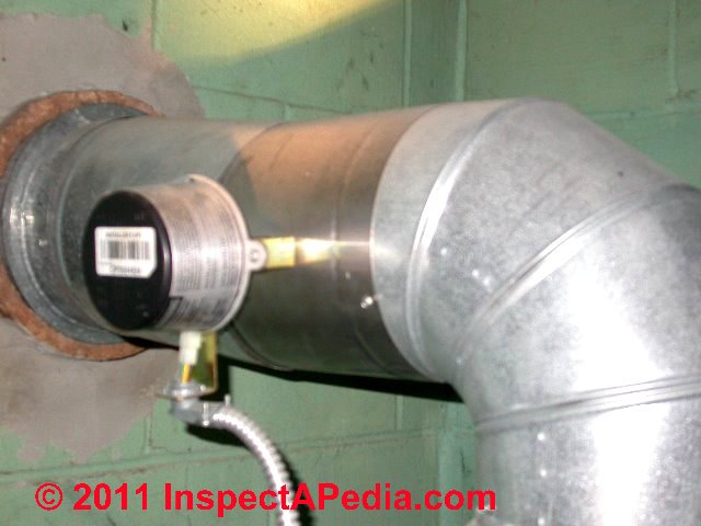
Is the draft regulator a field-installed retrofit unit (below left) or does it connect to a factory-built Tee (below right)?
Retrofit draft regulator opening size:
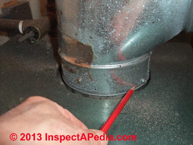
Why do we care if the damper is mounted on a field built tee or a factory tee? The draft regulator at above left is a field add-on that is installed using a two-piece eared collar provided by the manufacturer.
The components are installed by assembling the two halves of the collar and by cutting a a hole in the existing length of flue vent connector pipe. The eared collar is mounted over the hole in the flue vent connector and the draft regulator is mounted to the collar opening.
The size of the hole to be cut is determined by making a trace-mark inside of the mounting collar when the collar is held against the face of the flue vent connector in its destined location. On occasion we find that the hole cut in the pipe was too small (improper draft regulation) or too large (leaky connections).
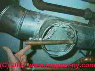
A field-installed damper mounting "tee" like the one at above left is secured to the flue vent connector by two sheet metal screws, one on either side (red circle).
If these screws are loose, stripped, or if the vent connector itself is corroded and rusty, the whole regulator assembly can fall off of the system - an unsafe event for obvious reasons.
The factory tee shown in our photo at above right (orange arrow) is secured to the boiler top and the flue vent connector (green arrow above the tee) using three sheet metal screws.
The draft regulator assembly(blue arrow) is also secured to the opening of the tee (at right) by one or in some cases more than one sheet metal screws. Inspect to make sure that the SMS are all in place and that the parts are not loose nor rattling..
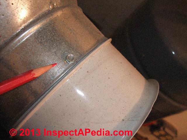
Loose-rattling draft regulator?
Interesting is that someone must have had trouble with this damper falling out or rattling, as they used adhesive-backed foil tape (blue arrow) to secure the regulator assembly to the field-installed tee.
The adhesive tape shown by our arrow is a clue to heating system operating history, or it might mean that the installer didn't know how or where to install the sheet metal screw (at the top and bottom of the regulator mounting ring) to secure it to the tee. Or maybe s/he was out of sheet metal screws.
Any clue suggesting unusual installation like this is an orange alert flag: look further for odd or improper workmanship.
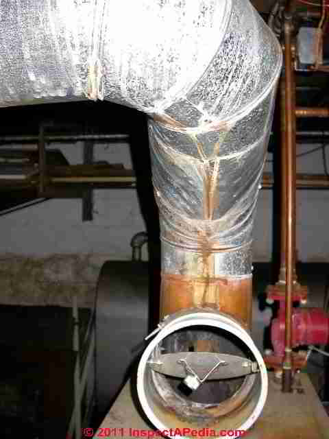
Soot & Debris inside the flue vent connector
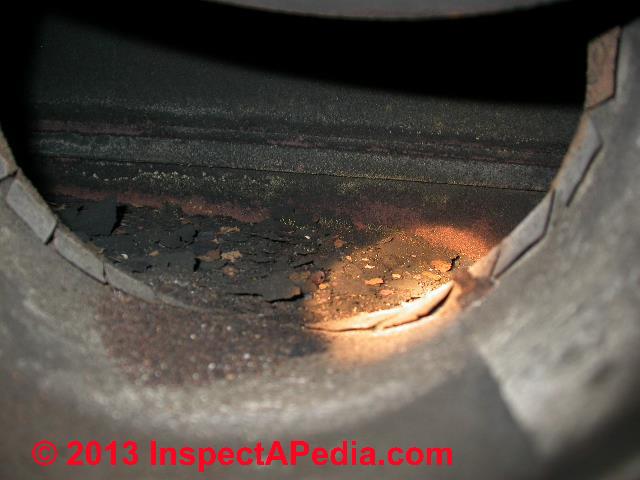
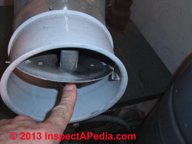
This photo shows how, simply by pushing open the draft regulator swinging door to inspect inside the unit you can reliably identify a field-installed cut-in draft regulator instructions - notice the bent-over tabs (green arrows) that were cut and adjusted by the technician.
As we elaborate
at DRAFT REGULATOR SOOT INSPECTION, this heater is also dirty (red arrow) and has not been properly maintained.
Screws Required to Secure Tee to Flue Vent Connector & Draft Regulator Assembly to Tee
The flue vent tee photo (below left) shows two of three sheet metal screws required to secure the tee assembly to the boiler top; three more screws are used to secure the tee to the flue vent connector ("stack pipe", not shown here) as well as three more (some instructions permit two) screws to secure the draft regulator assembly to the tee opening.
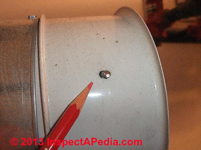
Our photos above and below show one of the screws required to secure the draft regulator assembly to the flue vent tee .
Usually we find that it's a tight fit jamming the draft regulator assembly into the tee opening, but we still install the factory recommended screws.
Vibration during heating equipment operation or the banging caused by rough heating boiler starts (mini "puff-backs") or other wear and tear can otherwise loosen the whole assembly.

Above we show where the draft regulator is missing one of its securing screws. There are several reasons why a screw might be missing:
The mounting screw was forgotten at initial installation
The mounting screw was removed to adjust the damper to proper level position, then the tech dropped the screw, it rolled under the boiler, and s/he didn't have another screw handy;
The service tech removed screws during cleaning (more likely at a flue vent connector not at the damper) and was in a rush to leave the job.
A close look at this photo shows that the damper position has been adjusted (to correct an out-of-level condition.
We can just see the originally-drilled screw hole in the damper assembly (red arrow) just above the original screw insertion hole (blue arrow) in the flue vent tee. Our orange arrow points to a 3/16" gap between the draft regulator fully-in raised stamping and the edge of the tee opening - not a serious concern as long as the device is properly secured.
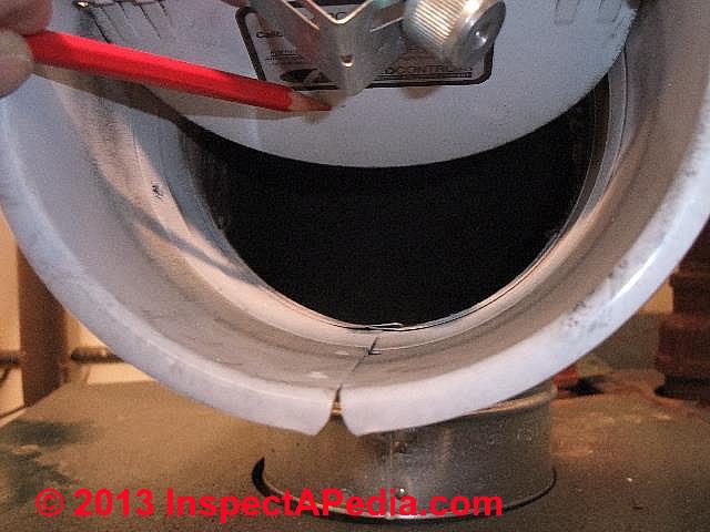
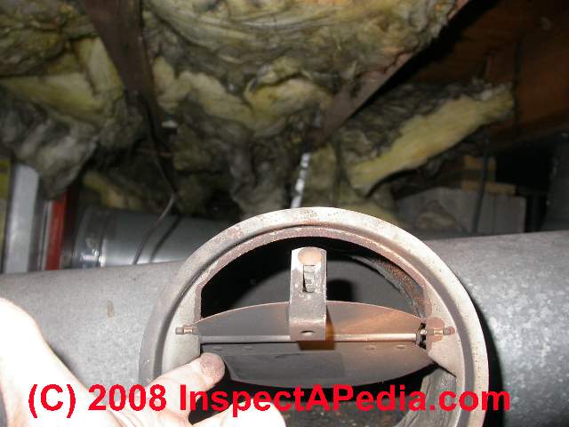
Check the Draft Regulator Door Hinge Pins
Our photos below (and my red pencil) point to the hinge pin that allows the flapper door of the barometric damper (or draft regulator) to swing freely. For the unit to operate properly the door needs to move freely in response to changes in draft in the flue.
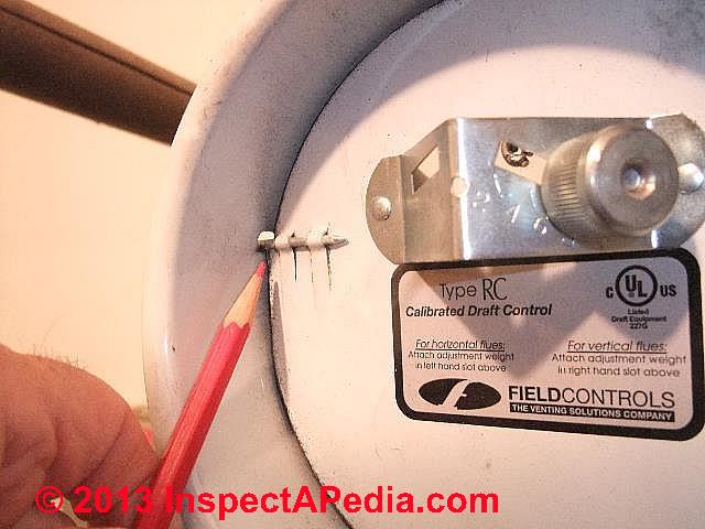
If the pins are bent, rusted, jammed, or field-modified (say a lost pin is replaced by a finishing nail) the draft regulator may not work properly and may even be unsafe.
Check the Draft Regulator Weight Assembly
Check that the weight assembly is present. You should see the bracket and adjustable weight on the outside of the draft regulator door (above my red pencil in the photo at below left). Now tip the hinged door open and check that the interior weight (red arrow in our photo at below right) is also in place.
If the inside weight has been lost it may have fallen into the boiler or furnace. If the outside draft control weight is missing look for it on the floor next to those missing sheet metal screws we mentioned earlier. Without the weights it is unlikely that a barometric damper can do its job properly.
Note: some draft regulator controls do not use weights on both sides of the control door.
Now use your finger or a tool to gently push the barometric flapper door open and let go - it should swing freely and should not jam open nor jam shut.
Check the Operating Environment for the Heating Equipment
Even a perfectly-installed draft regulator cannot overcome other combustion air, draft, chimney, or boiler/furnace operating defects from other causes.
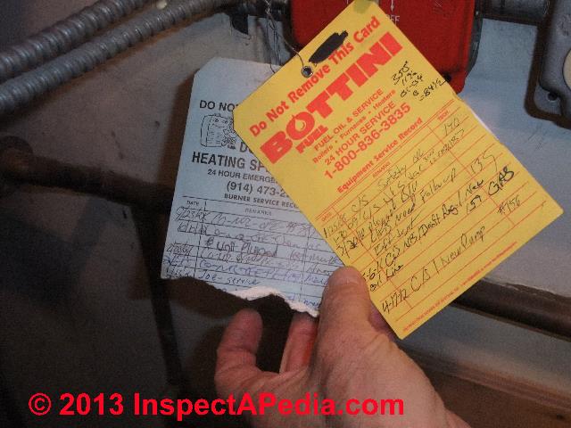
Check the service tag for the maintenance history of the equipment and for clues about a history of problems (repeated service calls for the same complaint).
Check the area around the heater for soot, oil spills, or an obvious lack of combustion air (tiny room, no air inlets).
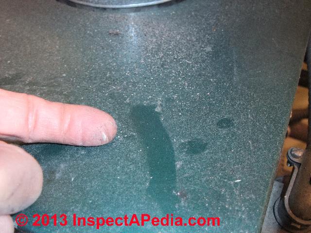
In a forensic investigation of a heating system problem I'd be worried about why the bottom portion of the older (blue) service tag has been torn off (photo above left). The service company doesn't want to leave the equipment with no service tag - that itself is a red flag. But what information did someone want me to not-see?
Our boiler top dust photo (above right) and my finger show that 6 1/2 months of operation and dust (July 1 to January 15) of this oil fired boiler has produced almost no soot blow-out. In fact the system is almost too clean - I wondered if it was running with excess combustion air - staying clean but maybe giving up on efficiency, thus increasing the building's heating cost.
Also see DRAFT REGULATOR SOOT INSPECTION where we provide details about what you may see when inspecting the draft regulator interior or the flue that it serves.
Typical Draft Regulator - Barometric Damper - Sizes & Costs
Barometric dampers or draft regulators (synonyms) are sold in a variety of sizes for residential and larger commercial heating systems. Draft regulator sizes are specified in inches, representing the diameter of the moving regulator door assembly.
Draft regulators are sized to match the flue vent connector to which they are mounted - in turn implying that the draft regulator will also be properly sized for the operating requirements (and draft requirements) of the heating appliance as well. That is, if the chimney and flue are too large or too small for the heating appliance the installation is improper and may be unsafe as well.
Sizes of draft regulators range from as small as 3-inch in diameter up to at least 32-inches in diameter. Prices for draft regulators range from under $50. U.S. to over $600. U.S. Larger sizes of barometric dampers, such as the Field 20-inch unit, retail (in 2013) for about $530. U.S.
Types of Air Regulators, Draft Controls, Fireplace & Stove, Dampers, Vibration Dampeners
This topic has moved to a separate article now found
at DAMPERS & DRAFT REGULATOR TYPES
covering all types of building and HVAC system air controls, dampers and dampeners such as automatic and barometric flue dampers used on heating equipment, coal stove, pellet stove, woodstove draft controls, draft inducer fans, HVAC duct air flow controls (manual register controls, duct dampers, zone dampers, automatic fire dampers, vibration dampeners), fireplace dampers, and fresh air supply dampers and controls.
Significance of Soot production or soot blow-back stains at the Damper or Draft Regulator
Soot production or soot blow-back stains at the combustion chamber inspection port or burner mounting tube (or soot in general).
Regardless of whether the draft regulator is serving an oil fired heating boiler or an oil fired water heater, soot coming out of the barometric damper or out of the flue vent pipe, or the presence of soot and burn marks on the heater, or even noises: stumbling, rumbling, noisy oil burners, as well as odors, are examples of improper oil burner operation that need prompt service.
Our photo at above left shows an example of improper oil burner operation on an oil fired water heater: both systems show soot blow-out at the water heater's combustion chamber inspection port.
At above right, a different heating system appliance shows soot beginning to blow back out of the draft regulator itself. And notice the sloppy installation? The draft regulator was not installed level. The weight system does not work properly when the damper door is out of level.
Often these soot marks are a symptom of excessive pressure or "back pressure" inside the combustion chamber. Since this water heater is connected so closely to the chimney in a pretty new house, our first guess was that the water heater itself needed cleaning.
Oil fired appliance sooting problems can be caused by an oil fired water heater or heating boiler that is way past due for cleaning (soot blocks the exhaust flue), by a blocked chimney, by improper draft regulator adjustment, or other defects.
When the oil burner is not operating, should the damper door be closed?
I am fascinated by and appreciative for your publication "Guide to Barometric Dampers..." Many thanks for the complete explanations.
I am getting the run-a-round from the 'service' people from the service company; I'm not sure they know much more than I.
I have one question which I hope you will answer: when the oil burner is not operating, should the damper door be closed? Logic would suggest to me that it should be closed but I am terribly uninformed. - R.D.B.
Reply: Generally, yes, at rest, the damper door is shut. But here are some things that might make it open:
A competent onsite heating or chimney and flue inspection by an expert usually finds additional clues that help accurately diagnose a problem with the heating appliance or the flue and chimney that vent its combustion products.
That warning made, yes, in general, a properly adjusted and balanced barometric "flapper" door is in the vertical or closed position when the heating flue to which it is connected is not in use. If the door is open you may be wasting warm air and heat from the area around the heating boiler or water heater that the damper is serving. Field Controls puts it this way:
Always set the [barometric damper draft] control to maintain as low a draft as will give good combustion and meet the requirements for heat. [1]
Why? Because if you set the draft higher than necessary, you are wasting money, sending heat up the chimney instead of into the building (or if it's a water heater, into the hot water tank). We need enough draft that the oil burner does not blow soot back into the building, and so that combustion is efficient, but we do not want excessive draft.
Below we list reasons that your draft regulator door is staying open.
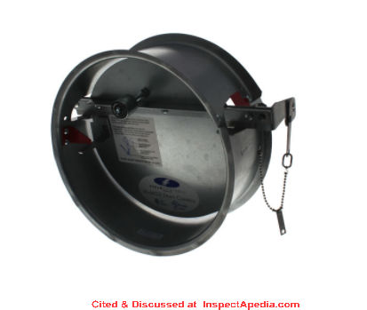
If you check all of these out and find that the installation is correct, the equipment is all operating normally, but that chimney and wind conditions are keeping the draft regulator open (and heat is thus wasted from your home), a solution could be the installation of an automatic flue vent damper that opens before the oil burner turns on and closes automatically when the oil burner has turned off. [See our photo at left].
Watch out: Installing an automatic flue damper can reduce building heat loss through the flue but we do not want to see this "solution" installed before you have an accurate diagnosis of just why your flue damper door is hanging open. We discuss automatic vent dampers in detail at Automatic Vent Dampers where we explain how they work, how they save money, and what they look like.
Here are some things that might explain why the barometric damper is hanging open even when the heater is not running:
The heater is cooling down:
If you are looking at the damper right after the oil burner has shut down, the heater is still hot and a mix of hot air and combustion gases are still zooming up the flue and chimney. If the draft effect of those rising gases is creating an updraft that is more than proper for optimum heater adjustment, the damper door will open to admit room air, thus reducing the draft seen in the flue.
The draft regulator is not properly adjusted.
One of the basic tune-up steps performed on oil fired heating equipment, usually right after the system is serviced and cleaned, is to check for proper draft over the fire and in the flue. The in-flue measurement is usually made through a hole drilled in the space between the top of the heater and the under-side of the draft regulator.
See What is the CORRECT DRAFT MEASUERMENT at Oil Fired Heaters?.
The draft regulator hinges or pivot pins are sticking.
On occasion, especially if someone was trying to "adjust" a draft regulator or damper by bending or banging on it, we find that the regulator's door hinge sticks. The door may stick in the open or shut position, interfering with proper operation.
It's easy to check for this sticky hinge problem: just gently push the door open and shut with one finger - it should move freely.
When the oil burner is off and the system is cool, if you can push the regulator flapper door into a position in which the door sticks and does not return to the "closed" position on its own, the hinge is binding or the damper is not properly installed. Sometimes a little cleaning and a dab of oil on a hinge (I used pencil lead) is needed. If parts are badly rusted or smashed, just replace the unit.
The damper is installed on a shared flue
or shared chimney: while it is not a recommended practice, if the damper is installed on a flue vent connector ("flue pipe" or "stack pipe" - the metal pipe connecting the heater to the chimney) that is shared with other heating appliances, then heat in the other appliance that is running or that has just shut down and is also "hot" can cause enough up-draft to cause the damper door to open.
In addition to the fire safety and code issues that severely limit any sharing of actual chimneys, the reason that manufacturers recommend that each heating appliance have its own flue damper is exactly this: you cannot adjust the barometric damper or draft regulator to optimize the performance of more than one heating appliance on a shared flue.
Details are at SHARED CHIMNEY & FLUE HAZARDS.
The draft regulator is not properly installed - out of level or in the wrong location.
A key reason that the manufacturers of draft regulators want the regulator face or "door" to be in the vertical position and the hinge axis of the door to be horizontal, is that the weight and calibration of the draft regulator adjustment and the response of the draft regulator to changing draft conditions depends on being in that position.
Even if the heating service technician adjusted the regulator for proper draft when the oil burner was up to temperature and running, if the damper is not properly installed it may not respond just right to changes in draft conditions such as wind over the chimney top.
In addition to out of level or wrong location, Field Controls also notes that the opening of the draft regulator should be pointing away from nearby walls or obstructions as these will interfere with its proper operation. Even if the installer placed the draft control properly plumb and level on the flue tee, if s/he forgot to set the locking screw (found at the bottom of the draft control assembly), the regulator may have rotated in its mount and may now be improperly positioned. [1]
Outdoor conditions are causing excessive chimney draft.
For example at some building sites and depending on variables such as wind direction, nearby hills, chimney height, roof shape, height of chimney top above roof, chimney cap design, nearby trees or other obstructions (yep there are a lot of variables), wind blowing over the top of a chimney can actually increase the chimney draft to a too-high level, causing the barometric damper to open even if the oil burner is not running.
- Dirk Faegre, Camden, Maine (207) 232-9494 is a certified BPI energy auditor and certified Envelope technician who kindly suggested draft regulator and flue vent connector inspection defect additions 6 Sept 09
Barometric Damper & Draft Regulator Control IO Manuals & Sources
- Field Controls, FIELD MG1 DRAFT CONTROLLER INSTRUCTIONS [PDF] - Field Controls, 2630 Airport Road
Kinston, NC 28504 USA, Tel: 252.522.3031 original source: fieldcontrols.com/wp-content/uploads/2019/05/46200000.pdf
Excerpt:
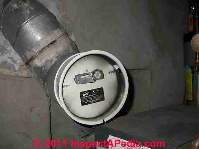
The Field RC is furnished as standard equipment on many leading brands of oil fired heating equipment. It is calibrated to allow for easy adjustment to the furnace or boiler manufacturer’s specifications. Designed for draft settings from .02” to 08” of W.C. - Field Controls, BAROMETRIC DRAFT CONTROLS Model 4" =7" RC [PDF] - retrieved 2023/11/01, original source: fieldcontrols.com/wp-content/uploads/2019/04/02702600_BAROMETRIC_DC_RC_4-7_RevC_04-15.pdf
- Field Controls, "Instructions for Installing FIELD Type AF Barometric Draft Controls," Form No. 31 DC 30666, Field Corporation, Mendota, IL 61342, web search 04/02/2011, original source: http://www.fieldcontrols.com/pdfs/04592700.pdf, Field Controls, Kingston, North Carolina 28501, Tel: 919-522-3031
- Tjernlund Draft Controls, A Series (single action for oil, solid fuel, and fan-assisted gas burners) and B Series (double action for gas heating appliances), web search 04/02/1011, original source: http://www.tjernlund.com/Tjernlund_8500490.pdf , Tjernlund Products, Inc., 1601 Ninth Street, White Bear Lake MN 55110-6794, Tel: 651-426-2993 or 800-255-4208 website: www.tjernlund.com Email: fanmail@tjfans.com
- See additional draft control manuals for gas fired heating equipment
at DRAFT REGULATORS / HOODS GAS HEATERS - draft regulation on gas fired heating equipment.
Reader Comments, Questions & Answers About The Article Above
Below you will find questions and answers previously posted on this page at its page bottom reader comment box.
Reader Q&A - also see RECOMMENDED ARTICLES & FAQs
On 2022-02-18 by Inspectapedia Com Moderator (mod) - draft regulation on an old EFEL Duffle Oil Burning Stove
@John,
Without the installation and operation manual for that oil stove any setting we'd suggest would be a wild guess and be so likely wrong as to not be useful.
In concept, you want higher draft in the breech over the stove than the draft measured over the fire.
That assures positive venting of the exhaust gases.
So you can't set the barometric damper accurately by eye alone, you'd need to actually measure the draft in those two locations.
As an EXAMPLE and quite different from your stove, a conventional oil burner will typically perhaps 0.02 " WC over the fire and 0.04 - 0.05 in the breech. So that's a reasonable difference for a powered device.
The draft on a "natural draft" stove like yours will probably be less, but the relationship of draft levels in the two locations would still be the same: more draft in the breech.
EFEL oil stoves, made in Belgium for over a century, are currently described as a Nestor Martin product.
If you are in the UK you could try contacting Edinburgh Stoves at https://www.edinburghstoves.co.uk/ to see if they have a manual for your Efel Duffel oil burner.
Edinburgh Gas Multifuel and
Woodburning Stove Centre
Stenhouse Mill Wynd, Edinburgh EH11 3XX
Tel 0131 202 1612
Or contact Nestor Martin at
https://www.nestormartinstoves.com/
On 2022-02-18 by John
I've got an old EFEL Duffle oil burning stove: a simple heating stove where oil is fed into a pan by a regulator valve and lit. There is no wick: just a burning puddle of lit heating diesel.
It is easy to adjust the regulator valve to a low setting where the oil buns blue just above the actuator around a circle of pin hole air vents.
The draft regulator is as you describe: on an opening on the back of the stove, entirely part of the flue. I never know where to put the weight: whether the circular regulator should remain balanced to open but swing closed, to stay closed or to stay open. All options are possible.
On 2021-11-03 by Inspectapedia Com Moderator (mod) - flapping banging noise at the door on my barometric damper
@CC,
Flapping of the barometric damper is comon bit not okay if it's continuous during burner operation.
That's likely to indicate a burner cleaning or adjustment problem, or a venting problem.
On the other hand, a single flap of the barometric damper door when the burner first ignites or shuts down is common and may not indicate trouble.
On 2021-11-03 by CC
Recently new piping installed in flu that the oil furnace vents into. There is a barometric damper on the vent pipe. Recently I've noticed when the furnace is running downstairs in the basement, I can hear the door of the damper flapping intermittently when the furnace is running while I am upstairs. Wondering if intermittent flapping of the damper door is normal?
On 2021-09-17 by inspectapedia.com.moderator (mod)
@NT,
No.
Because of the meaning of draft and draft measurements, (giving uplift so expressed as a negative number as opposed to "down-force" that would have been a positive number),
A draft of -0.04 is twice as strong as a draft of -0.02
On 2021-09-17 by NT
@inspectapedia.com.moderator, thanks!
So if I understand your explanation correctly, when the measurement is negative, it's the other way around: -0.04 is weaker draft than -.02 (-0.04 is less than -.02). So we do NOT want -0.04 at the breech and -0.02 over fire?
Please help confirm the bottom line. I have a Perfect Prime Manometer which reads -0.09 InH2O at room pressure (image is attached), I should adjust my dampener for my oil burner to have the breech reads 0.04 InH2O (not -0.04) and Over fire reads 0.02 inH2O (not -0.02)?
Thanks again very much for your help so I don't adjust to the wrong numbers!
NT
On 2021-09-16 by inspectapedia.com.moderator (mod) - what are the correct draft "pressure" readings
@NT,
First for clarity, when we measure draft we're measuring "negative pressure" that is, "suction" or updraft - the movement of exhaust gases or combustion products out of the heating appliance combustion chamber, through a flue vent connector, and into and up and out of a building chimney or vent system.
That said:
Always, for proper, safe venting of oil fired heating equipment we want to see
higher draft at the breech (above the boiler or furnace and before the barometric damper or draft regulator)
than we see over the fire;
This assures us of positive draft and venting for the whole system.
Why?
Because a larger draft number (e.g. 0.04" WC) is a stronger draft and a smaller draft number (e.g. 0.02") is a weaker draft.
If the draft over the fire were stronger than our draft measurement higher up in the system (just over the boiler or furnace itself) that would mean that the combustion chamber is going to become pressurized: the burner and combustion system are going to have trouble pushing exhaust gases out of the combustion chamber and up the flue.
That's dangerous and that also means the heater isn't going to work properly; it can also lead to sooting problems and loss of heat.
Above on this page we state
... typical draft settings or targets for oil fired heating equipment are given just below.
Normally we measure draft at two locations:
over the fire
or in the combustion chamber.
The draft we typically see on oil fired heating equipment like water heaters, boilers and heating furnaces is
- 0.02" to 0.03" water column (w.c.) in the combustion chamber just over the fire
- 0.04" to 0.06" w.c. in the breech - the flue pipe area between the top of the boiler and the bottom of the barometric damper.
Some oil burner models require higher draft than these numbers, and other oil burner models are actually tolerant of back-pressure in the combustion chamber (positive draft, or draft in the "wrong" direction").
Details about when, where, how and why to measure draft at oil or gas fired heating equipment as well as measuring draft for fireplaces, coal stoves, wood stoves etc. are
at DRAFT MEASUREMENT, CHIMNEYS & FLUES inspectapedia.com/heat/Chimney_Draft_Measurement.php
On 2021-09-15 by NT
Could you please help clarify on what the pressure reading should be in (a) inches of H2O over fire and (b) inches of H2O at breech for a Beckett AFG oil burner.
I see some area in this document states the breech should read -0.04 in H2O and other section states "Draft over the fire (typically set to 0.02" to 0.03" WC over the fire). Draft in the breech (always higher than the draft over the fire, and typically around 0.04 - 0.06" WC)." and am a bit confused.
Thank you very much!
On 2021-03-05 by danjoefriedman (mod) - the Field MG1 ddraft control is designed for gas fired heating equipment
@Roger Savoie,
Watch out: the Field MG1 draft control is designed for gas appliances; using any draft, chimney, or heating product in an application that is not one specified by the manufacturer could be dangerous, risking fire or gas or even fatal CO hazards; I would not modify nor use a control off-spec without discussing it with both the maufacturer and with your local code officials.
See these instructions from Field Controls:
FIELD MG1 DRAFT CONTROLLER INSTRUCTIONS [PDF]
original source: ieldcontrols.com/wp-content/uploads/2019/05/46200000.pdf

On 2021-03-05 by Roger Savoie
Hello, could I use a MG1 type draft control on my wood fired maple sap evaporator and if not, why? I understand that this type is for negative and positive pressures, why not just put a pin at the bottom of the "collar" so that the positive pressure could not open the door? Thanks!
On 2021-02-03 by danjoefriedman (mod)
Otto
Yes it's best to match the diameter of the barometric damper opening to the flue diameter; otherwise the draft control may be inadequate.
Every flue damper manufacturer makes their product in the range of flue diameters available. Below, for example, is the 10M-MG2 ten-inch barometric damper produced by Field Controls.
On 2021-02-01 by Otto Rodriguez
Hello! I cant seem to find an answer to this: I have a 10" flue, should I look for a 10" barometric damper or can a smaller damper work?
...
Continue reading at DRAFT REGULATOR SOOT INSPECTION or select a topic from the closely-related articles below, or see the complete ARTICLE INDEX.
Or continue reading at DRAFT REGULATOR, DAMPER FAQs - questions & answers about barometric dampers posted originally at this page.
Or see these
Recommended Articles
- CHIMNEY INSPECTION DIAGNOSIS REPAIR - home
- CARBON MONOXIDE - CO
- COMBUSTION AIR REQUIREMENTS
- DRAFT REGULATOR, DAMPER, BOOSTER - home
- DAMPERS & DRAFT REGULATOR TYPES - complete list that includes draft regulation on wood, coal, oil, and combination wood-oil fueled boiler and furnaces.
- DRAFT REGULATORS / HOODS GAS HEATERS - draft regulation on gas fired heating equipment.
- DRAFT MEASUREMENT, CHIMNEYS & FLUES
- GAS DETECTION INSTRUMENTS
- MANUALS for HEATING & A/C SYSTEM CONTROLS
- MANUALS & PARTS GUIDES - HVAC
Suggested citation for this web page
DRAFT REGULATOR, DAMPER, BOOSTER at InspectApedia.com - online encyclopedia of building & environmental inspection, testing, diagnosis, repair, & problem prevention advice.
Or see this
INDEX to RELATED ARTICLES: ARTICLE INDEX to HEATING SYSTEMS
Or use the SEARCH BOX found below to Ask a Question or Search InspectApedia
Ask a Question or Search InspectApedia
Try the search box just below, or if you prefer, post a question or comment in the Comments box below and we will respond promptly.
Search the InspectApedia website
Note: appearance of your Comment below may be delayed: if your comment contains an image, photograph, web link, or text that looks to the software as if it might be a web link, your posting will appear after it has been approved by a moderator. Apologies for the delay.
Only one image can be added per comment but you can post as many comments, and therefore images, as you like.
You will not receive a notification when a response to your question has been posted.
Please bookmark this page to make it easy for you to check back for our response.
Our Comment Box is provided by Countable Web Productions countable.ca
Citations & References
In addition to any citations in the article above, a full list is available on request.
- [1] "Instructions for Installing FIELD Type AF Barometric Draft Controls," Form No. 31 DC 30666, Field Corporation, Mendota, IL 61342, web search 04/02/2011, original source: http://www.fieldcontrols.com/pdfs/04592700.pdf, Field Controls, Kingston, North Carolina 28501, Tel: 919-522-3031
- [2] Tjernlund Draft Controls, A Series (single action for oil, solid fuel, and fan-assisted gas burners) and B Series (double action for gas heating appliances), web search 04/02/1011, original source: http://www.tjernlund.com/Tjernlund_8500490.pdf , Tjernlund Products, Inc., 1601 Ninth Street, White Bear Lake MN 55110-6794, Tel: 651-426-2993 or 800-255-4208 website: www.tjernlund.com Email: fanmail@tjfans.com
- [3] "Installation Instruction: the Field Controls Company, Draft Regulators (3"-10") Types B34 and DR", The Field Controls Co., 2308 Airport Rd., Kinston NC 28501-8947, Tel: (919) 522-3031 P/N 46001000 REV. A, retrieved 1/20/2013, original source: http://www.fieldcontrols.com/pdfs/46001000.PDF, copy on file as Field_B34_DR_Installation.pdf and as Field_B34_Installation.pdf
- [4] "Draft Regulator, Model B24-TJ", The Field Controls Co., 2308 Airport Rd., Kinston NC 28501-8947, Tel: (919) 522-3031 P/N 46001000 REV. A, retrieved 1/20/2013, original source: http://www.fieldcontrols.com/pdfs/46107700.PDF , copy on file as Field_B34_TJ_Installation.pdf
- [5] "Instructions for Field M + MG2 [Draft Regulator] Controls Without Collars", The Field Controls Co., 2308 Airport Rd., Kinston NC 28501-8947, Tel: (919) 522-3031 P/N 46001000 REV. A, retrieved 1/20/2013, original source: http://www.fieldcontrols.com/pdfs/01977200.pdf, copy on file as Field_B34_TJ_Installation.pdf
- [6] "Field M + MG2 [Draft Regulator] Barometric Draft Controls ", The Field Controls Co., 2308 Airport Rd., Kinston NC 28501-8947, Tel: (919) 522-3031 P/N 46001000 REV. A, retrieved 1/20/2013, original source: http://www.fieldcontrols.com/pdfs/01977000.pdf, copy on file as Field_M_MG2_Installation.pdf
- [7] "Barometric Draft Controls, Model Field R-C", retrieved 1/20/2013, original source: http://www.fieldcontrols.com/pdfs/DC01575700.pdf, copy on file as Field_R-C_Installation.pdf
- Field Controls Instruction Manuals - see http://www.fieldcontrols.com/instructionmanuals.php
- Lonny Steinke, Worland, WY USDA kindly corrected erroneous data we published on the proper draft numbers. - October 2008.
- Dirk Faegre, Camden, Maine (207) 232-9494 is a certified BPI energy auditor and certified Envelope technician who kindly suggested draft regulator and flue vent connector inspection defect additions 6 Sept 09
- In addition to citations & references found in this article, see the research citations given at the end of the related articles found at our suggested
CONTINUE READING or RECOMMENDED ARTICLES.
- Carson, Dunlop & Associates Ltd., 120 Carlton Street Suite 407, Toronto ON M5A 4K2. Tel: (416) 964-9415 1-800-268-7070 Email: info@carsondunlop.com. Alan Carson is a past president of ASHI, the American Society of Home Inspectors.
Thanks to Alan Carson and Bob Dunlop, for permission for InspectAPedia to use text excerpts from The HOME REFERENCE BOOK - the Encyclopedia of Homes and to use illustrations from The ILLUSTRATED HOME .
Carson Dunlop Associates provides extensive home inspection education and report writing material. In gratitude we provide links to tsome Carson Dunlop Associates products and services.
 | HOME | ABOUT | ASK a QUESTION | CONTACT | CONTENT USE POLICY | DESCRIPTION | POLICIES | PRIVACY | |
| © 2024 - 1985 Publisher InspectApedia.com - Daniel Friedman | |||||||||