
InspectAPedia® FREE Encyclopedia of Building & Environmental Construction, Diagnosis, Maintenance & Repair |
Question? Just ask us! InspectAPedia
|
 Fan & Limit Switch on Warm Air Furnaces
How the fan limit switch works
- POST a QUESTION or COMMENT about Troubleshooting the Furnace Fan Limit Switch
Furnace blower fan limit safety switch installation & troubleshooting:
This article describes in detail the purpose, operation, setting, installation, wiring, and testing of furnace combination controls, also commonly called the "fan limit switch" on warm air heating systems.
Covered here: How to Wire the Fan & Limit Control wire and test the combination fan and limit control on a furnace. Which Way to Set the White AUTO / MANUAL Fan Control Switch.
Sensing Furnace Temperatures How to manually turn on a furnace or air conditioning blower fan. Guide to troubleshooting heating system furnace controls, limit controls, and fan controls. Causes of furnace blowing cold air at start-up of heating cycle.
We also describe a Firstat duct temperature limit control that is a very similar device but used as a fire safety feature in building HVAC and building automation systems.
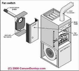
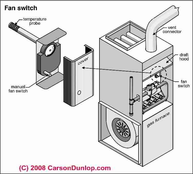
The sketch at the top of this page shows the typical location of a combination fan and limit control such as the Honeywell type L4064B, a control whose installation, settings, testing, & operation are explained in detail here. Sketch at page top courtesy of Carson Dunlop Associates, a Toronto home inspection, education & report writing tool company [ carsondunlop.com ].
InspectAPedia tolerates no conflicts of interest. We have no relationship with advertisers, products, or services discussed at this website.
What is the Function of the Hot Air Furnace Fan Limit Switch?
 The fan limit switch on a heating furnace controls when the furnace blower fan turns on and off. This control also provides a safety limit that turns off the burner or furnace if temperatures at the furnace are too high.
Fan/Limit switches are used on all types of building heating furnaces.
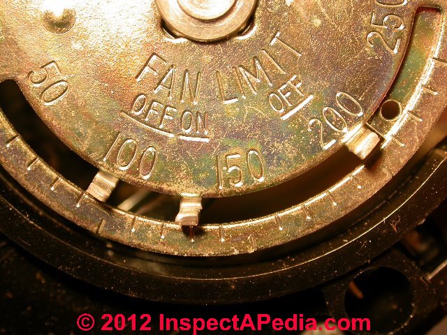
CLICK HERE to see a CLOSE-UP [image] of the FAN OFF, ON, and HIGH LIMIT OFF factory settings on this fan limit control.
A combined fan limit switch such as the Honeywell L4064 or the White Rodgers 5D51-90 limit control provides at least three heating blower fan temperature controls that respond to the temperature in the furnace supply air plenum:
[Click to enlarge any image]
1- FAN OFF:
the low temperature at which the furnace blower fan will STOP to prevent blowing cool air onto room occupants.
Typical factory setting: 90°F
2- FAN ON:
the temperature at which the blower fan will turn ON to begin to deliver heat to the building's occupied spaces.
Typical factory setting: 100°F
3- FAN LIMIT:
the high temperature at which the high limit switch will open (turn OFF) to stop the burner to prevent overheating of and damage to the heat exchanger. Such damage would make the furnace unsafe.
Typical factory setting: 200 °F
By keeping the fan off until the supply air plenum is warm, the heating furnace limit switch prevents the furnace blower from sending chilly air into the building if the oil or gas burner has not sufficiently heated up the furnace heat exchanger and supply air plenum.
Details about setting the temperature controls on a fan limit switch are
at FAN LIMIT CONTROL SETTINGS.
Watch out: when adjusting the temperature settings in this control do not press on, bend, twist nor in any other way fool around with the rotating metal disc. Doing so can bend its moving parts and spring, rendering the control both inaccurate and unsafe.
Furnace & Blower Fan Controls at the Fan/Limit Switch
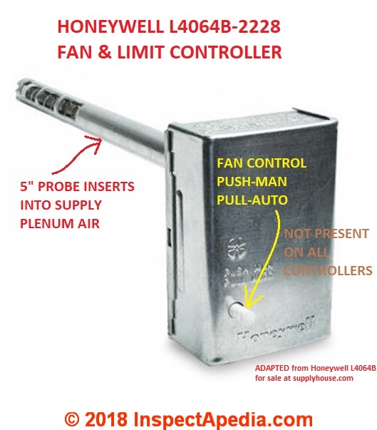
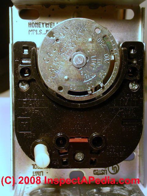 In this photo we see a Honeywell Tradeline L4064B 2228 combination furnace control. You can see the black switch body, the silver dial providing three temperature control settings shown on the face of the control dial.
The silver fan control dial shown in our photograph, driven by a bimetallic spring that is inside the probe that is in turn inserted into the supply air plenum, responds to temperatures inside the furnace. In response to supply air temperature this control turns the blower fan on, off, and provides an upper limit temperature setting for safety.
The wiring for this control is
at HONEYWELL FAN LIMIT SWITCH WIRING
4- MANUAL FAN CONTROL:
Many fan limit controls also include a blower fan Manual ON switch that can be set to cause the blower fan to run continuously.
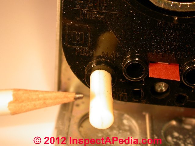
In our fan limit switch photo above on this page where you see the silver cover in place on the adjustable fan limit control, you also see a white push-pull switch (yellow arrow).
In our photo of the interior of the fan limit control immediately above you can see that switch again in the lower left of the image (white arrow).
Really? Ok so the "PUSH ON, PULL AUTO" switch is not present on every manual fan switch.
Some limit control models do not include this white button or switch to give manual control over the fan.
On the switch shown, pushing the switch IN puts the fan in MAN or always ON while pulling the white switch OUT restores the fan to AUTO operation
- it will turn on or off according to the supply air temperature and the FAN OFF, FAN ON settings on the control.
On the limit control in our photos imprints on the control label it PUSH MAN, PULL AUTO.
One reader has written that he finds limit controls at which the fan is put into manual continuous "ON" mode by pushing the switch in - though we have not found such cases.
Types of Fan / Limit Controls: adjustable vs. snap-disc
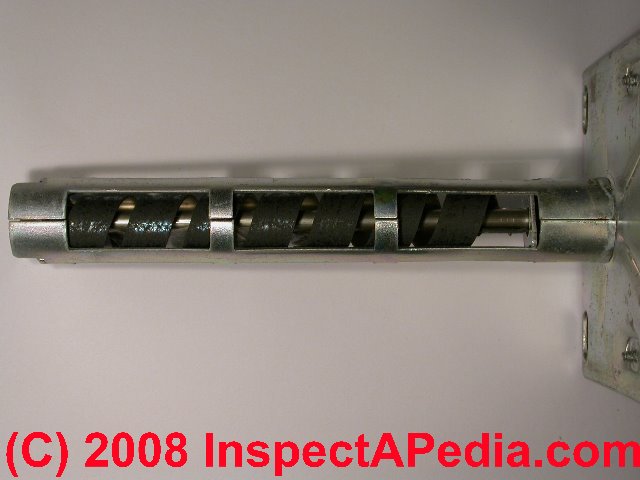
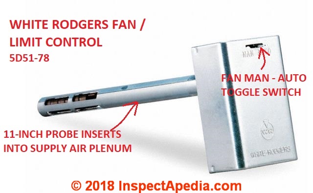 The White Rodgers adjustable fan/limit controller shown below provides a toggle switch at the top of the control. That switch allows the user to select MAN (fan will be always on) or AUTO.
This White Rodgers fan limit control sports an 11-inch long insertion probe that projects into the supply air plenum.
The wiring for White-Rodgers universal fan limit switches is
at WHITE RODGERS FAN LIMIT SWITCH WIRING
Also see WHITE RODGERS CONTROLS & MANUALS - all manuals
Watch out: for safety and for proper furnace temperature and fan operation it is essential that the fan limit control's temperature sensing device be located where the furnace manufacturer has specified and that the probe be of the proper length.
A probe that touches other metal parts or that is too short or too long will not work properly and the heating system may be unsafe.
You will see that the there are two popular Fan/Limit control switch designs:
- Adjustable Fan / Limit control:
A traditional-design adjustable combination fan and limit control (shown above) operates using a bi-metallic spring wound into a helix and inserted into the supply plenum.
The Fan switch "makes" or closes to permit the fan to run when temperature rises to the FAN ON setting.
The High Limit switch "breaks" or opens to turn the burner off if the plenum temperature reaches the high limit setting.
Two common brands/models of adjustable fan limit controls of this design are the Honeywell L4064B-series Fan and Limit Controllers White-Rodgers Fan/Limit Control Model 5D51-series.
An adjustable fan-limit controller typically is designed for furnaces operating at temperatures from 100°F to 250°F, has a FAN OFF lower limit that can be adjusted from 50°F to 200°F, a FAN ON switch adjustable from 65°F to 215°F and a fan HIGH LIMIT stop set at 200°F.
There are adjustable "stop" tabs that can prevent adjustments of Fan Off and Fan On beyond a particular point. The Fan-Off stop is factory set to 100°F and the Fan-On stop is factory set to 125°F.
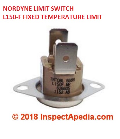
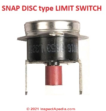
Above: a single-purpose snap-disc type limit switch from Nordyne, the Nordyne L150F.
A single purpose snap-disc type "limit switch" such as this one will "OPEN" to turn off the burner if temperature reaches or exceeds the switch's rated temperature, in this case 150°F.

- Fire Stat type temperature limit controls: (shown above & below)
The Firestat heating system duct control shown above is another type of fan limit switch that is typically installed int eating system ductwork at locations where the duct temperature can be monitored to be sure it stays below a critical level.
If the duct temperature exceeds the Firestat setting then the switch is used to turn off the building's heating system or other equipment. The adjustable model has a Setpoint Temperature Range of 100°F to 250°F.
See these
FIRESTAT LIMIT CONTROL INSTRUCTIONS [PDF] (2018) from Firestat, CEMCO (Division of Senasys), 1435 International Dr., Eau Claire WI 54701 USA, Tel: 1-715-831-6356 Email: info@senasys.com - retrieved 2023/12/04, original source: firestat.net/high-temperature-limit-control-installation/
FIRESTAT TC SERIES DUCT LIMIT CONTROL PRODUCT SPECIFICATIONS [PDF] (2010) Senasys, op. cit, - retrieved 2023/12/04, original source: h restat.net/wp-content/uploads/2022/04/TC-Spec-2010.pdf
Excerpt: The TC Duct Limit Controls contain a Helix Bi-Metal that senses rapid increases in duct temperature such as fire. The Bi-Metal causes the normally closed contacts to open and turn off the power. Available in either adjustable or fixed temperature models.

[Click to enlarge any image]
- Fixed-Temperature Snap-Disc controls:
Newer "snap-disc" type switches (included below), typically with one or at most two functions, that open or close an electrical circuit in response to temperature.
The temperature response point for snap disc controls is generally not adjustable.
Below, adapted from shopping suggestions from a Google search for "fan limit control" we show types of furnace fan and limit switches.

[Click to enlarge any image]
In the first limit control switch at the left in our illustration you see that a snap-disc type limit control is mounted on extending legs so that it can be placed at the furnace-manufacturer's required location in the supply air plenum.
The other snap disc switches in our illustration are all surface mounted and are often matched to specific brands and models of heating equipment.
Watch out: do not assume that you can easily swap out one type of furnace fan and limit control for another. Improper sensing of temperatures or control of the blower fan or burner can make a heating system unsafe.
Manufacturer's installation & adjustment instructions for each of the heating fan and limit switch controls discussed in this article series are found at References or Citations at the end of of each of our articles.
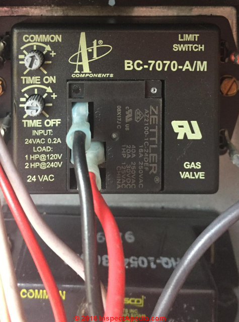
- Cam-stat® type Fan Limit Control Switch
such as the A-1 Components BC 7070 Blower Controller, shown above. This limit control, model BC-7070-A/M is produced by Zettler or A-1 Components.
This CAMSTAT type fan limit controller provides adjustable blower-on and blower-off times (time delay at the start or end of a heat-on or thermostat-controlled blower-in cycle) between 0-240 seconds.
For the BC7070 shown above here is a wiring diagram and very brief manual
- A-1 Components, BC-7070-A//M "ON/OFF" TIME DELAY RELAY FAN LIMIT CONTROLLER MANUAL [PDF], A-1 Components, Henry Technologies, Inc., 701 S. Main St., Chatham IL 62629, USA Tel: 217-483-2406, Websites: www.henrytech.com or www.a-1components.com
Product description: This fan limit switch is also referred to as a Cam-Stat control or a time-delay relay because it allows setting a timed delay in fan-on or fan-off cycles.
More about this and other furnace controls can be read
at MANUALS for HEATING & A/C SYSTEM CONTROLS
Ten Steps in the Sequence of Operation of a Furnace Fan Limit Control
Ten steps in operation of a forced-air heating system and the role of the furnace fan limit switch or limit control are described here.

Photo above: a General Electric Fan Limit control on an older gas furnace, courtesy of InspectApedia reader Zika. A typical GE Limit Switch model number was 3AHL5K2B8 but we don't have the model ID for the switch in our photo.
Like many other furnace plenum or duct temperature limit controls, these fan limit switches were sold with sensors at one of three typical lengths: 5-inch, 7.5-inch, or 11-inches.
The proper sensor limit length is, in some installations, important for the control to sense temperature correctly, and of course a too-long switch might be damaged or made unsafe by touching the opposite side of a plenum or duct surface.
The fan limit switch is a control which determines when the hot air furnace blower assembly turns on and off. In general, the sequence of operation of a forced-warm-air furnace heating system is this:
- The thermostat calls for heat,
either because room temperature at the thermostat has fallen below the thermostat setting OR because the occupants turn up the thermostat to a higher temperature setting.
The thermostat, acting like a simple on-off switch, tells the furnace, through low-voltage electrical wires connected to a control on the furnace, to turn "on". - The burner or heat source at the furnace starts
or ignites. Heat may be from a gas burner, oil burner, heat pump, electric heating elements, solar source, or another fuel or energy source. - The burner in the furnace heats a heat exchanger
through which building air will pass to be heated. But the blower fan does not turn on right away because we don't want to blow cold air on the building occupants. - The fan limit switch senses the temperature increase
in the furnace. The fan limit control includes a sensor (not visible in the photographs) that projects into the supply air plenum - on gas furnaces this is typically an area above the furnace heat exchanger.
The sensor, often a simple bimetallic spring, responding to heat rising from the heat exchanger that is being heated by the burner, mechanically rotates the temperature dial component of the fan limit switch. - The blower fan starts when the fan limit switch turns it on
When the temperature dial on the fan limit switch has rotated enough to represent a pre-set temperature (the FAN-ON temperature setting) the the fan limit switch turns on the furnace blower fan. - The blower fan moves warm air into the occupied space
The blower fan draws cool air from the occupied space, through return ducts, pushing that air up through the furnace heat exchanger where it is heated, and onwards through supply ducts to supply registers through which warm air is blown into the occupied area. - The furnace burner and the blower fan will continue to run
(usually) as long as the thermostat is calling for heat, so warm air is continually delivered into the occupied space. - The thermostat stops calling for heat
When the thermostat is "satisfied" - that is when the temperature of room air around the thermostat has reached the thermostat's set temperature - the thermostat will stop calling for heat - by in essence opening or turning "off" the switch that in turn tells the furnace that no more heat is needed (right now). - The blower fan extracts remaining heat
The blower fan continues to run for a minute or several minutes longer, extracting remaining heat out of the furnace heat exchanger and supply plenum, both for efficiency (avoiding wasting that heat) and to avoid possible damage to a heat exchanger that might otherwise become too hot. - The blower fan stops
Where is the Fan / Limit Switch Found on a Furnace?
In these illustrations we show to illustrations of a hot air furnace fan limit switch as you're likely to find one at a typical furnace.
The gas fired forced air furnace fan limit switch in the photo below is pointed-to by the red arrow.
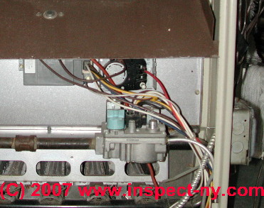
The oil-fired furnace fan limit switch shown in our photo below is in use on an oil-fired warm air furnace where we can see about 3/4 of the silver colored dial where the fan limit switch settings are made (red arrow).
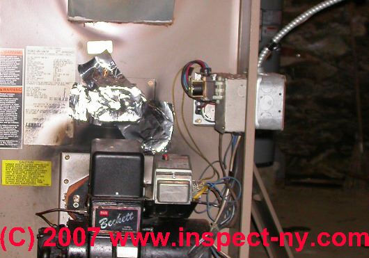
Watch out: Don't let your focus on a specific control device blind you to other important signs of the condition of a heating appliance.
In the left side of the same photo above, soot and foil tape above the oil burner assembly also tell us that this system has been operating improperly with back pressure in the combustion chamber. Such a system might be unsafe.
Really? Well not always. A heating system duct temperature limit control might also be installed at critical locations in ductwork, typically in a commercial HVAC system or as part of a building automation system. See our description of the Firestat at FAN LIMIT CONTROL TYPES.
Safety Features of the Furnace Fan / Limit Control Switch
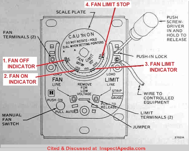 Click to enlarge the fan limit control switch sketch below to read the names of its various parts and controls.
The fan limit control includes these key features
- A manually-operated blower fan on-off switch
(on some, not all fan/limit controls) - A temperature sensor in the furnace,
either a probe with bimetallic spring or a snap-disc type temperature sensor. We described both of these sensors earlier in this article. - A FAN control switch
that turns the blower fan on or off in response to the furnace air temperature - A LIMIT control switch
that turns the burner or heat source off if the furnace becomes dangerously hot
Sketch courtesy of Carson Dunlop Associates, a Toronto home inspection, report-writing tool, and home inspection education company.
Watch out: The fan limit switch is also a safety control which protects the furnace heat exchanger from damage (such as heat exchanger cracking due to overheating) by turning the heat source or burner off at the furnace should the temperature inside the warm air supply plenum (just above or just next to the heat exchanger) gets too high.
If a furnace heat exchanger overheats there is risk that the heat causes a crack that in turn could leak dangerous combustion gases or potentially fatal carbon monoxide into the occupied spaces in the building.
 [Click to enlarge any image]
Overheating at the furnace heat exchanger is an unusual condition but it does indeed occur if any condition obstructs air flow through the heat exchanger.
Obstructed air flow can occur because of a dirty air filter, blocked or disconnected air ducts, or if someone has fouled up the system controls.
Details: In normal warm air furnace operation, by moving building air across the heat exchanger, the blower is warming air that will be delivered into the occupied space, but at the same time this process is keeping the heat exchanger from reaching too-high a temperature.
If a furnace blower fan fails to start but the furnace heat source (gas or oil fired burner) is running, the heat exchanger would be come overheated and may warp and crack.
The fan limit switch is designed to prevent this damage by shutting off the burner if plenum temperatures reach the high limit.
A fan limit control switch is found on both oil and gas fired heating furnaces of all types.
When does the furnace blower turn OFF in normal operation?
As we show this control in our photo at left, usually the adjustable-type fan limit switch of this type has a silver cover hiding the switch details.
If a manual fan ON/AUTO control is provided you will see (on Honeywell controls) the white "fan override" button or for White Rodgers controls a sliding metal toggle switch projecting through the cover of the control. .
Provided that the fan switch is in AUTO position, when the thermostat has been satisfied and turns off the oil or gas burner at the furnace, the fan limit switch will cause the blower or fan unit to continue to operate just until the temperature at the supply plenum has reached or dropped below the FAN OFF lower limit on the switch - the blue arrow in our photo above.
Then the control will turn the blower fan OFF.
When does the furnace oil burner, gas burner, or other heat source turn OFF in normal operation:
On many warm air heating systems, at least during cold weather, the burner or heat source will continue to run all of the time that the building thermostat is asking for heat, and will stop running as quickly when the thermostat is satisfied.
If the furnace oil or gas burner is very high capacity, or if the furnace fan/limit controls have been set to cause this effect, the burner may on some systems cycle on and off periodically while the warm air blower continues to run.
Which Way to Set the White AUTO / MANUAL Fan Control Switch
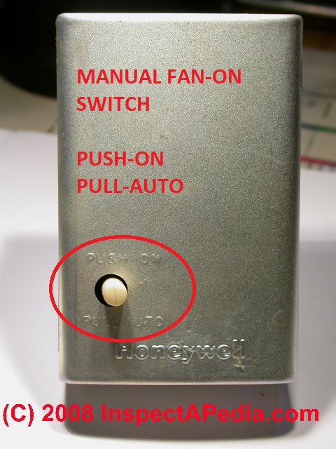
On the silver cover of the fan limit control switch shown in our photo above the cover embossing indicates that PUSHING the button IN forces the fan ON mode.
"PUSH ON" is functionally the same as PUSH MAN (embossed on the switch body itself as we show at left) - it means that you are manually setting the fan to remain on continuously.
On the identical fan limit control shown with its cover off - at left, you can see (click to enlarge) that the text embossed into the switch body says PUSH MAN instead of PUSH ON shown on the switch cover.
Pull this button out to cause the fan to run automatically (AUTO) - meaning that the switch itself will turn the blower fan on and off in response to furnace plenum air temperature. Summarizing:
- PUSH the white button IN to force the fan to ON or MANUAL or always-running mode.
Some control guides call this "Summer Use" or "Summer Fan" using the blower fan to circulate air when not in the heating season. - PULL the white button OUT to put the fan back into AUTO mode
- turning on and off under control of the switch and furnace temperature.
Thanks to reader Rob for pointing out the confusion about the fan control AUTO - MANUAL switch positions on the fan limit control.
On systems where we have installed high quality air filtration to address an indoor air quality issue, and where the fan is rated for continuous duty, we may pull this switch out to keep the fan on continuously.
How the Fan Limit Switch Senses the Temperatures Inside a Warm Air Furnace
Above we've already discussed the controls and settings of the fan limit switch. What we haven't explained is how the switch senses temperatures in the furnace. The fan limit switch contains a bi-metallic spring (shown at left) which is inserted into the warm air plenum of the heating furnace.
As the air in the furnace plenum warms up the bimetallic spring expands, turning a gear which turns the fan limit control dial (shown in the photo above).
As the fan limit switch control dial rotates, mechanical "fingers" on the back of the dial operate electrical contacts inside the switch to turn the fan on or off and at the upper limit to turn off the furnace oil or gas burner as well.
When you move one of the little sliding temperature set points on the face of the dial you're moving the position of the mechanical fingers on the back of the dial.
Bypassing the Fan Limit Switch
 Question: I bypassed the limit switch and the heater worked fine, but when I tried to test the air conditioner it would not work
I have a Goodman PGB048075-1 furnace. The high limit switch is bad. I bypassed the limit switch and the heater worked fine, but when I tried to test the air conditioner it wouldn’t work.
Is that because I need to replace the high limit switch in order for the air conditioner to work. Or will it work with the limit switch bypassed. I already know the high limit switch is bad.
But just want to know why the heater works but not the air conditioner with the limit switch bypassed. - Brian
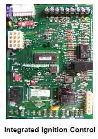
[Photo, left, the integrated ignition control circuit board from a Goodman furnace. [1]
Short Answer: your bypass of one safety control may be detected by the primary controller, resulting in system operation shutdown. By-passing the limit control is very dangerous and can also destroy the equipment.
A competent onsite inspection by an expert often finds additional clues that help accurately diagnose a problem with furnace controls, but we agree that it makes complete sense to start with a known, obvious failure - in this case you point to the limit switch.
We have read a few other Q&A's on bad limit switches on the Goodman Furnace model PGB048075-1, though not all of them actually tracked back to a bad switch.
Though your question focuses on why the A/C won't run in cooling mode with your limit switch "bypassed", there are a few things to check right away:
Watch out: bypassing any HVAC equipment safety control such as a limit switch is dangerous, risking overheating and unsafe conditions.
Also bypassing the limit switch and can result in permanent damage to the equipment (such as heat exchanger warping and cracking), fire or carbon monoxide hazards, or other failures that leads to having to replace the unit. Quoting from a Goodman installation manual:
Watch out: WARNING TO PREVENT PREMATURE FAILURE OF HEAT EXCHANGER, PROPERTY DAMAGE, PERSONAL INJURY OR DEATH, DO NOT ADJUST THE LIMIT CONTROL (FACTORY SET).
The Goodman Furnace model PGB048075-1 is a mid-efficiency natural gas furnace with an AFUE rating of 80%. Manuals are available from Goodman and other online sources.
I attach a copy of a 2004 Goodman Furnace manual that may be of some help. Page 26 of that manual describes checking the primary limit control. You'll notice that nowhere does Goodman endorse any wiring modifications such as bypassing the control.
The furnace manual includes an excellent furnace troubleshooting chart that decodes the meaning of the diagnostic lights on the primary control LED. This might help you make sure that you've correctly identified the trouble with your unit.
The Goodman company describes the safety controls on this furnace line as follows
Warning: for general guidance the below is quoted from the furnace manual described at References. Details for your model may vary:
The primary limit control guards against overheating resulting from insufficient conditioned air passing over the heat exchanger
If the primary limit control does not function during this test, the cause must be determined and corrected. Function of this control should be verified by gradually blocking the furnace return air after the furnace has been operating (burners firing) for approximately ten minutes.
Because your furnace uses an integrated control module (an electronic device that controls all furnace operations) it is certainly possible that the control module, which monitors all of the safety circuits, is not permitting the unit to run with your modification to the safety limit control. The company describes the various safety controls on this equipment as follows:
Primary Limit Control, Goodman Furnace
The primary limit control guards against overheating resulting from insufficient conditioned air passing over the heat exchanger. If the primary limit control does not function during this test, the cause must be determined and corrected.
Function of this control should be verified by gradually blocking the furnace return air after the furnace has been operating (burners firing) for approximately ten minutes. Check the control as follows:
- Allow the furnace to operate with burners firing continuously for approximately ten minutes.
- Gradually block the return air to furnace. Remove airflow
blockage when limit control is activated and turns off burners.
Airflow blockage causes unit overheating and will produce
the following reactions:
- The gas valve to close and extinguish flame,
- The induced draft blower to be de-energized after a fifteen second post purge, and
- The circulator blower to remain energized continuously until limit control resets.
- Remove the return air blockage to clear overheating condition. After an acceptable temperature is reached during the cool down period, the limit control will reset and allow the furnace to resume normal operation.
Watch out: WARNING TO PREVENT PREMATURE FAILURE OF HEAT EXCHANGER, PROPERTY DAMAGE, PERSONAL INJURY OR DEATH, DO NOT ADJUST THE LIMIT CONTROL (FACTORY SET).
Safety Circuit Description for a Goodman Furnace
... These checks establish that the primary limit control is functioning and will respond to a restriction in the return air, or a circulator blower failure. If the primary limit control does not function during this test, the cause must be determined and corrected.
General note on furnace safety circuits
A number of safety circuits are employed to ensure safe and proper furnace operation. These circuits serve to control any potential safety hazards and serve as inputs in the monitoring and diagnosis of abnormal function. These circuits are continuously monitored during furnace operation by the integrated control module.
Integrated Control Module on Goodman Furnace
The integrated control module is an electronic device which controls all furnace operations.
Responding to the thermostat, the module initiates and controls normal furnace operation, and monitors and addresses all safety circuits. If a potential safety concern is detected, the module will take the necessary precautions and provide diagnostic information through an LED.
Primary Limit Control on Goodman Furnace
The primary limit control is located on the partition panel and monitors heat exchanger compartment temperatures. It is an automatic reset, temperature sensor.
The limit guards against the overheating as a resulting of insufficient air passing over the heat exchanger.
Auxiliary limit control on Goodman Furnace
The auxiliary limit control is located either on or near the circulator blower and monitors heat exchanger compartment temperatures.
The control is a temperature sensor. It guards against overheating resulting from insufficient air passing over the heat exchanger.
Rollout Limits on Goodman Furnaces
The rollout limit controls are mounted on the burner/manifold assembly and monitor the burner flame. They are manual-reset, temperature sensors. This limit guards against burner flames not being properly drawn into the heat exchanger.
Pressure Switches on on Goodman Furnaces
The pressure switches are normally-open, negative air pressure activated switches. They monitor the airflow (combustion air and flue products) through the heat exchanger via pressure taps located on the induced draft blower. These switches guard against insufficient airflow (combustion air and flue products) through the heat exchanger.
Flame Sensor on Goodman Furnace
The flame sensor is a probe mounted to the burner/manifold assembly which uses the principle of flame rectification to determine the presence or absence of flame.
References - where to get a Goodman furnace manual
- Goodman Manufacturing Company, L.P., 2550 North Loop West, Suite 400, Houston, TX 77092, www.goodmanmfg.com See Goodman Mfg Gas Fired Central Furnaces INSTALLATION & OPERATING INSTRUCTIONS GAS FIRED WARM AIR FURNACE AMV8 [we attached a copy to our emailed reply to this reader]
See GOODMAN HVAC MANUALS & ERROR CODES for access to Goodman heating and air conditioning equipment manuals and installation instructions.
Reader Comments, Questions & Answers About The Article Above
Below you will find questions and answers previously posted on this page at its page bottom reader comment box.
Reader Q&A - also see RECOMMENDED ARTICLES & FAQs
On 2023-12-04 by InspectApedia Publisher
@Zika,
Continuing...
Sources / Types of CO Detectors that Work at Low Temperatures
We've read that there are two problems using smoke detectors and some CO detectors in low temperature environments: ionization type smoke detectors and battery operated smoke or CO detectors may not be reliable.
However a detector that plugs into a 120VAC wall receptacle should work - at least to avoid the cold battery problem. < Take a look at the Kidde HD135, described in its manual as Kidde HD135
For CO detection at low temperatures you probably need to look at commercial models that are in the $100 - $200. price range. Perhaps a Macurco unit.On 2023-12-04 by InspectApedia Publisher
@Zika,
I am not confident that your heating system is safe, and I add (being cautious and considering how little we know about your system and the expertise of people involved) that unless your friend is trained in gas heat service and heat exchanger testing, you shouldn't bet your life on his inspection.
We've published quite a bit on this question, starting at
HEAT EXCHANGER LEAK TEST
On 2023-12-04 by Zika
Thank you for your advice, I will be over there later this week and test it out. Maybe I can convince a friend who has a boiler license to test the heat exchanger.
The flue pipes are 26 gauge galvanized steel. It was that or 30 gauge at the HDepot so I choose the thicker of the two. Fairly sure these aren't meant for flue gas but are for heated air distribution inside a hone.
I do have an AC Carbon Monoxide detector in the garage stamped 2017 on the back so it's reached the ~7 yr expiration date. That will be replaced.
FYI for readers, nearly every CO detector I have looked at has a 40° F minimum operating temperature. If anyone knows of a common affordable residential model that has a lower temperature range I'd love to here about it.
Thanks again! I will have more information on this install and performance next weekend. If you have more questions please post and I'll gather the info and pictures.

On 2023-12-04 by InspectApedia DF (mod) - running a gas furnace in a garage kept at low temperatures: settings & risks
@Zika,
OK those additional details are helpful, and important.
Thoughts on running a gas furnace in a garage kept at low temperatures: settings & risks
The GE fan limit switch in your photo is at a reasonable setting for the use you're making of the furnace and it ought to work "as is".
However if you set a bit higher FAN-OFF temp that might seem to be appropriate for running the system in a very cold garage.
Here's my thinking and OPINION (I'm not the world's expert on this point)
1. When the temperature drops to or below the thermostat setting the thermostat - in essence a simple on-off switch - calls for heat at the furnace controls (including the fan limit control).
2. The furnace will turn ON and will continue to run until EITHER the thermostat is satisfied OR the furnace hot air supply plenum temperature (where the fan limit switch is normally mounted) reaches the FAN OFF temperature.
I suspect, and this is how furnaces usually work, that in a cold garage, on a call for heat the furnace will simply run continuously until the thermostat is satisfied. That's because the cold air returning from the garage keeps cooling down the furnace plenum.
So it's probably irrelevant, but in concept, we set the fan OFF to a higher temperature that should mean that on a call for heat the burner would run longer before turning off.
So in sum you should watch how the furnace runs when the thermostat calls for heat. IF you see the furnace cycling on and off frequently you might try raising the fan off temp.
A concern:
Running any heating equipment, but especially a gas fueled furnace heater and at settings that might give a short and infrequent on-cycle (which is indeed might be the case when you're keeping the thermostat set to a very low temperature) risks corrosion in the furnace at its heat exchanger (this is VERY dangerous and risks fatal carbon monoxide poisoning if the heat exchanger leaks) and also corrosion in its exhaust vent or flue.
That's because corrosive condensate in those areas accumulates - they are not being kept warm and dry.
So besides
1. watching the furnace to see if it has long on cycles (best),
2. be sure you have working smoke and carbon monoxide detectors installed, properly located and tested regularly, including in the garage
3. ask your heating service company to have the system inspected and tested by an experienced service technician who knows how to inspect for and test for heat exchanger leaks and any other safety concerns.
Do keep us posted; what you add will help other readers.
See more about Ten Steps in the Sequence of Operation of a Furnace Fan Limit Control above in this article.
On 2023-12-04 by Zika
 @InspectApedia Publisher,
"Honeywell
Model CT50K
Special Feature
Low Temperature
Great for use in garages or outdoor buildings
Wide temperature range for setting to desired temperature
Bimetal temperature sensor offers simple and hassle-free operation"
What install looked like before all the vent pipes replaced, (in same configuration). Again, just trying to tweak install for max efficiency, working with what we have.
On 2023-12-04 by Zika
@InspectApedia Publisher,
It's pumbed will city natural gas off a Tee feeding the homes furnace. actually been in operation off and on for 15+ years probably only a few years all winter at the low setting of around 40°+ using an old round gold honeywell mercury switch thermostat at its lowest setting.
Last December swapped that thermostat for a Honeywell electronic thermostat that goes down to 35° for this type of application. Seemed to perform ok from listening to my dad, uril last week when I found all the flue venting pipes corroded and leaking.
Replaced all those last week cleaned inside and out and added a 20x25x1 filter over the intake. That's when I discovered the fan speed switch and limit switch, undoubtedly still set where they were when it was installed in a ~2000 sq foot walkout rambler at the time.
I have a some pictures of the wiring diagram inside the maintenance panel and other details. I'll try to post another pic with this reply....
I will try to decode the pictures I took later but think what I can read says 100,000 btu, fan type 70-105° temp rise @
static . 20, . It is a two car garage real rough guess of ~22ft x 26ft with a ~8-9ft ceiling?
On 2023-12-03 by InspectApedia Publisher
@Zika,
This looks like an old furnace possibly repurposed from somewhere else. A couple of preliminary questions
What's the fuel, oil, gas?
Is this a new application or do you have some experience using this furnace in this cold garage?
Do you have a thermostat that you can set to turn on at the low maintenance temperature that you were describing?
On 2023-12-03 by Zika
So I have an old GE furnace (60+ yrs old) installed in a MN garage to keep the temp around 35°-38°, the fan limit dial is set to 90°, the range is 80°-135°.
There is also a big toggle switch for high and low fan speed set to high.
Outside temp will vary from about ~ -10°- +40° the next 4 months. The garage and door is insulated.
The plenum is an open ~18" x 18" grate at the ceiling pointing forward.
Any advice on fan limit setting and speed in this install? It's a garage and I only turn it up occasionally to 60° to work in there for a few hours otherwise it's just keeping the cars and concrete slab above freezing... Thanks!
On 2023-11-28 by InspectApedia Publisher - repairing the internal parts on that fan limit control risks making it unsafe
@Bob R.,
I'm sorry to say that I think the control needs to be replaced.
The worry is that any effort to repair the internal parts on that fan limit control risk making it unsafe.
For emergency heat and where the limit switch had no manual fan-on switch, you may be able to turn the blower fan on continuously at the thermostat or by direct wiring.
Take care to avoid a shock.
On 2023-11-28 by Bob R.
My furnace's Honeywell fan limit switch fails to turn on the blower fan, but it does shut off the burner when it reaches 200F. When the dial rotates to the lower limit, fan control wiring side (left) isn't closing (tested with multimeter). FYI, the blower fan works well when AC is running.
Is it possible to make the left side connection close when the dial reaches lower limit to turn on the blower fan? If so, how to repair it? BTW, there's no manual fan ON/AUTO control button on the switch. Thanks,
On 2022-01-20 by Inspectapedia Com Moderator
@Regina Caeli (PJ),
I did say before that I thought these settings were reasonable as you described but of course the final technical authority would be the manufacturer of your heating equipment.
150 F imo is not extreme.
Still, ...
Watch out: There is a concern that constant cycling of a furnace between quite cold and quite hot temperatures increases the risk of cracking in the heat exchanger. Ultimately that could cause a flue gas leak into the house which could be quite dangerous.
So it's also worth investigating why the return air is so cold and whether you should be installing additional return air sources from the occupied area.
On 2022-01-20 by Regina Caeli (PJ)
@Inspectapedia Com Moderator,
Yes, the burners stay on and when the temperature goes up to the FAN on temp again, the blowers come back on. I know the standard is 130 but I have pushed it to 150 with FAN off temp about 70. IS there any problem with keeping the FAN on at 150?
I have had no problem with the upper limit at all, whenever the blower stops, the burners are always on and when I check the dial on the fan limit switch, it is never near the upper limit.
To me, it seems that the fan limit switch is doing its job so I don't have to replace it. But I would like to know if that is your thinking also.
On 2022-01-20 by Inspectapedia Com Moderator - blower will turn off to avoid sending cold air
@Regina Caeli (PJ),
Your guess sounds reasonable to me. If incoming return air temperature and volume is so cold and so much that it cools the furnace plenum temperature so that it drops below the FAN ON temperature then the blower will turn off to avoid sending cold air to the occupants.
But in that case the burner should continue to operate and when it raises the plenum temperature back to the FAN ON temp then the blower should turn on again.
The proper settings are given at FAN LIMIT CONTROL SETTINGS
Normally I'd stick with those. But if your temperature adjustment has got you heat that may be OK. You did not mention the upper temperature limit setting - that's also important for safety.
Watch out: moving the tabs or adjusting the fan limit control is dangerous. It is too easy to accidentally bend the internal spring behind that rotating wheel; if the springs are bent then the switch is no longer properly calibrated and it could be unsafe.
On 2022-01-20 by Regina Caeli (PJ)
@Inspectapedia Com Moderator,
The temperature at the thermostat is not going up. The air from the ducts is not very warm. If I raise the fan off temperature to 90, the blower keeps going off after only running 45 seconds.
I have observed the fan limit switch and the temperature drops about 30-40 degrees when the blower comes on. I have it set at 140 for the fan on temperature.
It takes awhile to build to that but when it does come on, the temperature drops to about 100. Then is holds for about a minutes and then it drops below the the 90 fan off temperature and the blower goes off.
I have pushed the fan off temperature down to 70 and this keeps the blower on but then the house temperature at the thermostat does not get over 64.
It seems that the fan limit switch is doing its job.
The only return is on the side of the furnace and it is at floor level on the ground level of my home.
Since a thermometer on the floor near this return reads only 50, I think that the air coming in is just too cold for the furnace causing the big drop in temperature in the plenum when the blower kicks on.
On 2022-01-19 by Inspectapedia Com Moderator - Burner is on and blower fan is running but temperature is not going up
@Regina Caeli (PJ),
Burner is on and blower fan is running but -which?- temperature is not going up:
- temperature in the occupied space at the thermostat? - check the delivery of warm air to the occupied space: look for a dirty air filter, collapsed, disconnected or crushed heating duct
- temperature in the furnace itself, at the plenum? - watch the fan limit switch dial: it will rotate towards a higher temperature as the plenum heats up; It should not be possible for the burner to run without heating the plenum at the furnace itself.
On 2022-01-19 by Regina Caeli (PJ)
The burners are running and the blower is running but the temperature is not going up. The flame is strong and blue, the filter is new, all the registers are unobstructed.
The only return is the one on the furnace itself which is at floor level and since the house has been cold for 12 days, it is still pretty cold air going into the furnace. Is there any other possible reasons that the temperature is stuck at 64 even though the burners and blowers have been working constantly now?
I have moved the fan limit tabs and settled at 150 for blower on and 80 for blower off. This has allowed the furnace to finally reach the 70 that it was set at. My question now is whether this 150 is safe to keep the furnace at?
After being set lower overnight, it again has taken all day to climb up to 68 degrees. The burners stay lit but the blower goes off every couple minutes. I have noticed that the pilot light flame is not very long. Could it be insufficient?
I thought that if the pilot did not hit the flame sensor directly, thus causing it to not be hot enough, this would make the burners go out, not the blower stop.
On 2021-04-20 by danjoefriedman (mod)
@Dan Roux,
Apologies but I'm not sure what you mean by incomplete or complete circuit. Perhaps you could use the add image button to post a sketch.
On 2021-04-20 by Dan Roux
Coleman said could put adjustable low limit switch on model 7856-856 forced air furnace, purchased at021 - installed incomplete circuit? Put old back on circuit complete, can't understand why circuit would go incomplete not allowing furnace to operate?
On 2021-01-29 by (mod) - 1988 Amana Gas Furnace Blower fan early shut-down traced to bad limit control switch
 Excellent going, Billy;
You've been on the track of this limit switch from the get-go. And the result will help other readers.
For other readers: this limit switch is for the
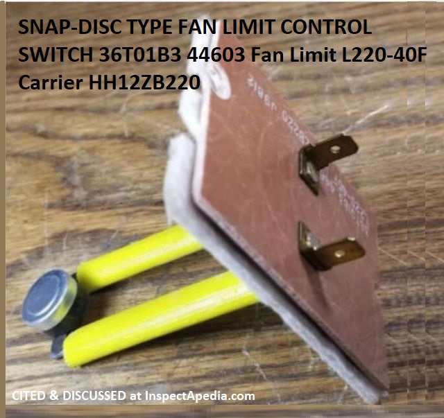
Amana Air Command Hi Efficiency 80 Gas Furnace - Model GCI115X35A P1155313F - Year 1988
We can see from the additional photo I've adapted from a 36T01B3 44603 Fan Limit L220-40F Carrier HH12ZB220 for sale on eBay that your Amana gas furnace limit control switch is indeed a snap-disc type controller;
Newer models of this switch may orient the snap disc in parallel with the extension arms and the arms may be black instead of yellow; the part is often listed as "discontinued" but available as "new old stock".
An alternative that IMO is perhaps safer, is essentially the same switch but that opens at a slightly lower temperature than the original - as you noted and as we see in vendors offering a primary limit controller opening at 215°F.
it is not adjustable;
if it stops working as it should the right repair is to replace it.
HVAC parts suppliers list this switch as something like
107283-26 Amana High Limit Switch L220-40F
Amana 3" Limit Safety Switch 220 Degrees
Models Number GC1A, GCIA070A30.
10728326 & 107283-26
Limit L220 Degree Cut Out -40F Cut In 180 Degrees
Also see this AMANA GOODMAN SERVICE & TROUBLESHOOTING GUIDE [PDF] for 80% Single Stage Gas Furnaces GMES80, AMES80, GCES80, ACES80, VMES80, VCES80 & Accessories
where on p. 33 you'll find "CHECKING PRIMARY LIMIT CONTROL" that describes testing the limit control.
On 2021-01-29 by Billy
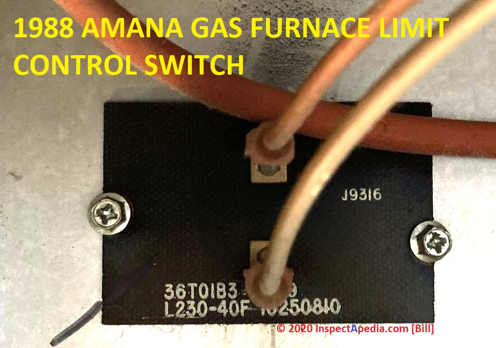 It was the Limit Switch in the heat exchanger, it was opening at 180F degrees which was the hottest the air ever achieved in the exchanger, this Limit Switch isn’t supposed to open until 230F
It was the furnace’s original switch made in 1988.
I’ve ordered an OEM replacement but it’s rating is 220F, I think it’ll be fine, pic attached is the original.
Thank you :)
On 2021-01-27 by (mod) - “MRLS” = “Manual Reset Limit Switch” ?
Nah, MRLS, I like it; I just don't know all the acronyms .
The MRLS itself may be simply located at a convenient spot while it might be triggered by a sensor in the appropriate location.
Do try it.
On 2021-01-26 by Billy
“MRLS” = “Manual Reset Limit Switch” I apologize, used my own acronym and it won’t happen again. My blower fan is at the top of the furnace, pretty much in its own housing, the Manual Reset Limit Switch is mounted there so it’s in a much lower temperature environment..
it’s nowhere near the plenum or burner, which is why I’ve hesitated to push it in as it may be wired to the thermostat, it’s 2 electrical wires go directly into the control board.
I’m going to let the furnace cool way down and then push this button in, if it fails to solve the problem or causes another problem to solve I’m calling a tech service.. there’s a reputable one that charges $69 to diagnose the problem, most likely I can fix it from that point - if I can’t then I needed the service anyway and they then apply the $69 to their work.
Thank you so much sir, I’m a Luthier of stringed instruments by profession & my father was an auto mechanic.. so I’ve got the tools/feel multimeters etc but lack the education of knowledge on gas furnaces, they look to be a simple apparatus but without knowledge it’s not so simple + I can’t talk the language of which I’m thankful for your tolerance of me.
I’ll post back up when it’s solved and reveal what it was for the sake of this thread to maybe help others going forward.
On 2021-01-26 by (mod) - furnace uses snap-disc controls not a traditional fan limit switch
OK so your system uses one or more "snap disc" devices that monitor temperatures and act as the necessary controls, rather than a conventional fan limit switch. Both types of controls are shown on this page.
Sorry I'm not sure what an MRLS is - perhaps you can post a photo.
On 2021-01-26 by Anonymous
Thank you sir, I understand. It does have a "Manual Reset Limit Switch" that is stand alone without a dial, my furnace/system does not have a dial on the fan limit switch.. there’s nothing like the pictures of this dial on this forum of my furnace.
I’ve been replied on another forum (doityourself.com) that my "Manual Reset Limit Switch" may be a substituted modification - I do remember when I needed a new thermostat
3-4 years ago, the tech said my original simple thermostat was no longer available and I had to convert to quite an expensive fancy modern thermostat.. maybe he installed this “MRLS” then, I don’t know, I do know the sticker/decal stating & pointing to it is much newer than being original on the furnace - with that said, this little switch is covered in dust and looks never touched.
Lastly, I replaced the high limit switch a few days ago.
On 2021-01-25 by (mod) - why does the furnace blower fan run a bit after the burner turns off?
Not quite: the key purpose of the fan running a bit past the end of call for heat at the thermostat is to cool down and extract heat from the plenum in the furnace - otherwise we risk oveheating and cracking the heat exchanger that in turn would risk fatal CO poisoning.
IF the purge cycle is shorter that might occur if the airflow has been improved through the system by any means: new filter, cleaned the blower fan, fixed a crimped duct, etc.
You can confirm that indeed the heater is shutting down too early if you watch the dial on the fan limit switch: at the end of heat cycle when the blower continues to run you'll see the dial rotate to a cooler temperature until it reaches FAN OFF.
If the system shuts down before that temperature is sensed then the switch is probably defective.
Or if the limit control shows that the system is cooled down to FAN OFF but you are sure that the heater is still too hot, then the limit switch sensor may be soot fouled and the switch would need replacement.
If your system has actually got a "Manual Reset Limit Switch" then it may be using a snap-disc type limit control; some of those, when popped, need to be permitted to cool down and then manually re-set by pushing a button right on the snap-disc sensor itself.
On 2021-01-25 by Billy
*The end/last cycle of the blower running to expel the last heated air out of the ducts/registers is running 45s less than it used too, it was always perfect and not shutting off until air out of the registers became luke warm. In other words there’s still strong heat left in the system bc the end cycle is shutting off too soon.
Mounted to the blower housing and wired to the control board is a small switch with only 1 button on it, a large decal stating “Manual Reset Limit Switch” with an arrow pointing directly at this 1 button switch. It would help greatly if I could find out what this switch does if I push it in.
There are no other controls/dials etc., just the push button on this part. Attach the schematic in case it helps, hope it’s readable upon zooming.
Also - the flue is fine, no measurable soot in the plenum.
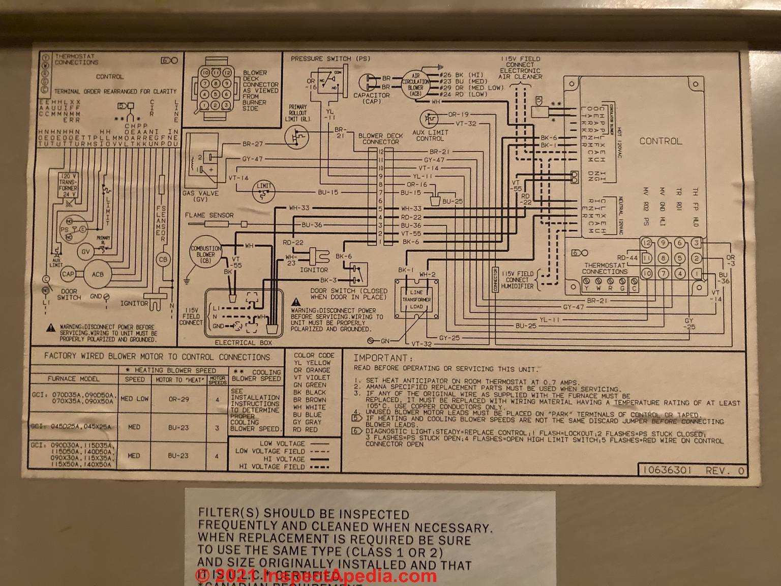
Above: wiring diagram for Amana Air Command Hi Efficiency 80 Gas Furnace - Model GCI115X35A P1155313F - Year 1988
[Click to enlarge any image]
On 2021-01-25 by (mod) - furnace Fan shuts off too soon
"Fan shuts off too soon" ? can you explain a bit more - too soon relative to what?
Good going on noticing that the door interlock switch can leave your heater shut down. It's a common mistake and one I've mentioned from time to time _ I should have thought to include that in our discussion earlier.
On 2021-01-24 by Billy - furnace would not run because the door was not shut - door safety interlock switch keeps system OFF
I should add that the end cycle has been shutting off about 45 seconds too soon in recent days, this is the same wether the old limit switch or new one installed, still good heat in the ducts.
Furnace now running, I didn’t have the front panel installed correctly so the safety switch of recognizing panel was installed securely wasn’t engaging. Furnace still has original problem but isn’t giving me any flash codes, furnace does run better now and is more quiet & smooth, the problem clickclickclick is much quieter & not so aggressiv
I’ve read this model does shutoff the gas about every 5m for a bit, a design feature making it more efficient, the fan inducer motor never stops when it performs this, however when the problem ‘clickclickclick’ shut off happens the fan inducer motor does shut off & recycle back on.
Thankfully I found the original flash codes inside the furnace housing, if only Amana had the identifying parts diagram I could have fixed this weeks ago, also would’ve been able to communicate with you better - of which I’m quite embarrassed + all my unnecessary elaborated posts, I’m very thankful for you & all you’ve shared.
my furnace is looking & performing much better in many ways because of you.
I haven’t pressed in that manual reset limit switch button (on the blower) yet, I’m afraid something might go wrong until understand it better, it seems this might have to do with running the fan continuously but I don’t know as it might fix the problem as it seems to maybe comply with the new limit switch I installed.
Well I’m off to find the where & what is the ‘Open’ High Limit Switch the 4 flashing code is crying for. Lastly, calling Amana only results in them telling me to call one of their techs or buy a new Amana, they won’t give up anything about older models! I like my model, it’s clean & well kept, besides I named her Little Bertha years ago - so I’m attached to her like an old car <3 thank you ever again sir, mr friedman
On 2021-01-24 by (mod)
I'm not sure and I will look at this further but yes if there's a reset button you should try it as many heaters use a manual-reset button.
On 2021-01-24by Billy
 Thank you so much for all. I’ve replaced the limit switch, photo included to make sure we’re both talking of the same thing because there’s a ‘manual reset limit switch’ up on the blower fan, what I replaced (pictured) is mounted above the burners.
Furnace now does not start or run after replacement - does it make a difference which of the two connectors (ie pos/neg) the two wires connect to my replaced part? Was I supposed to press the little button on the ‘manual reset limit switch’ located up on the blower fan? I have the correct oem part, all installation and reassembly went perfect. ASAP lol, it’s getting cold :/ Lastly I found the flash codes,
4 flashes = Open High Limit Switch, I’ve yet to research it but will as I wait for your reply
On 2021-01-18 - by (mod) -
Please find our discussion now at the Reader Q&A section near the bottom of AMANA HVAC MANUALS & PARTS GUIDES - inspectapedia.com/heat/Amana-HVAC-Equipment-Manuals-Contact.php
You may need to clear or refresh your browser cache to see the updated page. We welcome your further photos, comments, questions.
also see GOODMAN HVAC MANUALS & ERROR CODES - inspectapedia.com/heat/Goodman-HVAC-Manuals-Error-Codes.php
where the 4 flashes error code for Amana and Goodman furnaces is described.
On 2021-01-18 - by (mod) -
Billy
With the immediate life safety worry under control per your vigilance, what's next;
If the heater is being cycled off by the limit control we ought to see the temperature dial reaching the upper limit or close to it;
Some techs advise removing the limit control and cleaning the sensor - typically a bimetallic spring wound in a spiral.
I'd be nervous about relying on that approach; though I might try it as an experiment I'd instead replace the limit control switch and I'd inspect the plenum for sooting.
According to Amana's error code guide,
Four LED flashes indicates a Pressure issue. High limit cut-off due to faulty wiring or bad filters.
Recommended action: Replace or clean the air filter; clean drain tubes of moisture or debris;
May have an open limit switch that requires a jump, ensure not to run it with the main switch bypassed.
It was a disappointment to visit the Amana website where the company either has hidden or simply decided not to offer any Amana furnace troubleshooting help; Goodman brand diagnostics may still work for Amana gas furnace owners.
On 2021-01-18 y Billy
Thank you sir, yes I've been checking and monitoring ever since the problem arose, I've found no flue gas spillage or any gas abnormalities. I should de-emphasize the "flashing flames" as I saw this only once upon the unit fighting itself back & forth to shut down or not - this is the "clang-clang-clang" which is actually more of a "chatter" like a "click-click-click...
it's very quick and appears to be the thermostat telling the furnace "no we haven't reached my temperature setting yet" but a safety in the furnace is saying "to hell with you i'm shutting the gas off" in other words they're fighting each other in this brief moment - then draft inducer motor shuts off for 15 seconds, starts back up igniter glows and all runs perfect to finish.
Is there instructions to the knowledge & tools needed to perform a complete cleaning of the flue, or can this only be achieved via a professionally trained tech? Still getting the 4 code flashes during the failing moments.
On 2021-01-1 by (mod) - check safety conditions first such as flue gas spillage
Billy
I would check safety conditions first such as flue gas spillage
On 2021-01-1 by Billy - Amana Air Command Hi Efficiency 80 Gas Furnace - Model GCI115X35A P1155313F - Year 1988
Amana Air Command Hi Efficiency 80 Gas Furnace - Model GCI115X35A P1155313F - Year 1988
Furnace starts and goes thru all phases nicely to running perfect for 3-5 minutes, then the burner flames go out and it immediately
starts trying to fire again 3 to 8 times in very fast repetition making a clang-clang-clang sound as slight flames shoot
on-off-on-off-on-off...
then it calms down for 20 seconds during which the draft inducer motor shuts off and starts up again then
the igniter glows back up and it fires perfectly and runs great for 3-5 minutes...
this cycle repeats itself, usually just once,
until the home reaches thermostat set temperature of which then the shut down cycle is perfect. I must note three of every four
times the furnace will perform its entire cycle perfect without the above problem. Lastly, I've seen the "flashing red light"
producing 4 flashes during the problem, but I don't know the code's meaning...
owners manual, parts diagram, and flashing code
meanings cannot be found on Amana's website nor anywhere on the net in my searches.
I replaced the flame sensor but that was not the problem. The filter is clean and properly installed, intake vents and registers
are clean, the pressure switch & draft inducer motor seem to be working good, quality new in home thermostat is only 6 months old.
I believe it's either the flue needs to be removed from the draft inducer motor & cleaned, or the fan limit switch mounted above
the burners is failing.
If anyone has experience or knowledge of this same problem, possibly familiar with this furnace model, I would appreciate the help
and any knowledge or questions, thank you. -Billy
Moderator reply: oil burner not heating the plenum enough to turn on the blower fan - going off on reset?
Michael
Your first point sounds entirely reasonable and right to me. I'd have replaced the switch too.
That corroded helix might have meant that the sensor - basically a wound-up bimetallic spring - was not responding to temperature. So we agree again.
Properly the fan does not turn on until the plenum is sufficiently warm, so as to avoid blowing cold air on building occupants, and the fan continues to run for a time after the burner stops, to extract remaining heat and reduce chances of heat damage to the heat exchanger.
When the burner turns on, if it truly is unable to heat the heat exchanger and thence air in the plenum enough to cause the limit switch to turn on the blower then that's pretty unusual and points first to the 2 items I listed.
Of course your service tech may find something else - even a subtle issue like a corroded or bad electrical connection (that might respond to heat).
For example, beyond an improperly-operating oil burner that isn't putting out enough heat or a blocked heat exchanger, your furnace could simply have an oil burner that is way out of tune, running sooty and smoky, thus tripping a safety control that shuts down the burner - or even simply a bad flame sensor or cad cell eye.
But when the whole system has cooled down such that on a call for heat the burner can't warm up the plenum enough to turn on the blower fan then I suspect it's one of the 2 problems we've now both listed.
Those are not things a homeowner can safely fix; a heating service tech, if she agrees that the furnace needs cleaning, will disassemble some of the furnace, vacuum out the soot, do the same for the flue and chimney, then clean and tune the oil burner, replacing the filter, screen, and nozzle; then to properly set the burner air and fuel unit pressure instrumentation is needed - stuff you won't have and aren't trained to use.
Forgive me for hedging in a reply like this, but in my experience, almost always, when I'd go to the home of someone who had reported and described the conditions of a building or mechanical system problem I'd find something else that was important or necessary to know but that simply wasn't so obvious to the homeowner who wasn't someone who did that work all the time.
Reader follow-up:
Michael said:
The original problem was that the fan would not start when I would call for heat. I would start the burner w/ the relay switch... and the fan would not start. I was able to manually turn on the fan at the limit switch.
All of the research I had done suggested if - the fan will only stay on when manually turned on - it was the limit switch that needed replacing. The fan motor not being the problem.
After I replaced the limit switch... I inspected the old limit switch and found some corrosion on the end of the open rod that holds the helix. I figured... that was the problem.
The motor/burner is less than 2 years old by the way.
I was under my house this morning and I went through the steps of restarting the burner several times to get the fan limit switch to turn to fan on.
Now... keeping the thermostat at 70 degrees... it works just fine. When the temp drops below 70... it calls for heat... and the burner turns on... and the fan shortly after. I suspect this is because the furnace is still warm from recently being on.
The burner appears to work fine... it’s heating my home now... no problem... as long as the furnace stays warm.
- the burner is not working properly
- the heat exchange is blocked/clogged
Are these problems I can fix... or do I need to call a professional.
On 2020-11-22 by (mod) - why won't the fan come on: plenum does not get hot enough to caused the limit switch to turn on the furnace blower
Michael:
Let's back up: what problem was being solved when you replaced the fan limit switch in the first place? Is it possible that that problem was not diagnosed correctly and that the switch was not the problem?
It sounds as if you replaced the control because you were already having this problem of the plenum temperature not getting hot and then the limit control not turning on the fan.
The fact that on repeated restarts you ultimately heat up the plenum and the fan works and the limit control works, suggests that the problem is either
- the burner is not working properly and not pumping in enough heat fast enough
or
- the heat exchanger is blocked or soot clogged, so not enough heat is being transferred fast-enough into the plenum
More diagnostic suggestions are
at FURNACE FAN WONT START
Watch out: for other readers (as Michael's is an oil furnace) a blocked heat exchanger can also make the heater unsafe. In particular if this is a gas system and it's making soot there is high risk of a fatal carbon monoxide poisoning hazard.
Anon
(if you are not Michael)
Thanks that's a helpful question: why won't the blower fan turn on and stay on.
Watch out: if the burner turns on and the fan limit switch dial rotates to show it's sensing warmer temperatures and then continues to rotate all the way up to the FAN HIGH LIMIT where it turns off the burner then your heating system is unsafe and the problem may be that the fan won't turn on. See the FURNACE FAN WON'T START live link I give just above.
Have you watched the dial and indeed seen that it does not rotate at all as the plenum warms up? If that's the case the control may be defective.
But if the dial rotates all the way around to FAN OFF at the HIGH limit on the control quickly (perhaps in 60 seconds) the the problem may be that the blower isn't turning on, so not enough air passes through the heat exchanger, and thus the control is turning off the burner to avoid overheating and cracking the heat exchanger ( that can be a fatal hazard).
On 2020-11-22 by Anonymous
Any advice on why my fan limit switch will not get hot enough to move the dial to... fan on... when I call for heat and the burner runs for 60 seconds before shutting off?
On 2020-11-22 by Michael
I have a Thermo Pride oil furnace. I recently replaced the fan limit switch. Did not mess with the dial.
My problem is with the plenum temp not getting hot enough to move the limit switch dial to... fan on. And without the fan turning on... the burner shuts off after it runs for 60 seconds when I call for heat.
The thermostat is set 10 degrees above room temp to make sure it will call for heat.
However... when I watch the limit switch dial... and call for heat several times... increasing the plenum temp each time I push the reset button on the relay switch... the dial will turn until it’s hot enough to turn the switch on. Then... everything works just fine. Burner works... and blower fan works.
But if I turn the temperature down on the thermostat... and let the furnace cool down... my problem repeats.
I have to go back into my crawl space and push the reset button on the relay... several times (burner only runs for 60 seconds without the fan turning on) to get enough heat to the limit switch to get it to move to the fan on position.
I’ve replaced the relay switch... fan limit switch... and the fan motor run capacitor.
On 2020-10-02 - by (mod) -
Please see the Fan Limit control settings described at
FAN LIMIT CONTROL SETTINGS
On 2020-10-02 by Anonymous
what to set limit/fan at
On 2020-08-21 by Chris
I have a older heater with blower and the heater won't turn on and the blower turns on randomly. Could this just be a bad fan limit switch or has the thermostat gone bad also?
On 2020-02-1 - by (mod) - Goodman gas furnace / air handler error code consisting of 4 flashes
Jim
The Goodman gas furnace / air handler error code consisting of 4 flashes may vary by model, but the usual meaning is
that the primary limit circuit open.
Causes include
Loose wiring or a bad electrical connection such as at a control board
Dirty or blocked air filters.
Repair:
First Check and clean or replace any/all air filters
Second: tighten any loose electrical connectors
Third: have your heating service technician check the flue for blockage - this is an important safety check.
If you don't have the IO / user's manual for your Goodman IMP gas furnace you can download a copy at
inspectapedia.com/aircond/Goodman-Gas-Furnace-Manual-GMP100-4.pdf
Or see AMANA HVAC MANUALS & PARTS GUIDES
See a complete table of Goodman gas furnace error fault codes at
AMANA & GOODMAN HVAC MANUALS & ERROR FAULT CODES
On 2020-02-08 by jim
i have a goodman gas furnace.model# gmp 100-3 i am getting a code of four flashes.condition:limit switch open. action:gas valve off. circulator on. inducer on.
On 2020-01-29 - by (mod) -
Let's start by asking you to have a look at the Honeywell limit switch wiring
at HONEYWELL FAN LIMIT SWITCH WIRING
On 2020-01-29 by deryck baird
I replaced a limit switch on an old furnace and got it working, but when i tried to tie in the thermostat through the low voltage side of the limit switch its not bringing on the furnace. Could you help? the limit switch is a Honey well L4064B
On 2020-01-08 - by (mod) -
Jim
Thanks for the nice comment.
A short-cycling blower fan during the heating cycle does, as you suggest, usually mean that the plenum is overheating and in turn that's often because of reduced air flow through the heat exchanger, such as caused by a dirty air filter, a blocked air duct, or simply inadequate return air in the first place.
There could be a more-subtle issue such as a loose wiring connection or even a faulty fan relay.
On 2020-01-08 by jim
This is excellent information.
My issue is that my furnace calls for heat just fine and the proceeds to go through the expected sequence.
t gets to a point where the unit then starts short cycling the fan. When I go to inspect the unit I can hear it bouncing back and forth and the gas blower jets are still flaming...
would I be right to assume that this is because it needs to stop blowing hot air as the flue may be blocked? it has a new filter installed so not that...I also replaced the limited switch...could it possibly be the flame sensor also?
...
Continue reading at FAN LIMIT CONTROL SETTINGS or select a topic from the closely-related articles below, or see the complete ARTICLE INDEX.
Or see FAN LIMIT SWITCH FAQs - questions and answers posted originally on this page
Or see these
Recommended Articles
- AIR HANDLER / BLOWER UNITS - home
- FAN, AIR HANDLER BLOWER UNIT
- FAN MOTOR START CAPACITORS
- FAN, COMPRESSOR / CONDENSER UNIT
- FAN LIMIT SWITCH
- FAN LIMIT CONTROL SETTINGS
- FAN LIMIT SWITCH INSTALLATION & WIRING
- FAN LIMIT SWITCH TROUBLESHOOTING
- FAN RUNS ONLY ON FAN-ON / MAN
- FAN WONT STOP - LIMIT SWITCH
- FAN WONT STOP - THERMOSTAT SWITCH
- FURNACE BLOWS COLD AIR
- FURNACE FAN CYCLES AFTER HEAT
- FURNACE FAN CYCLES DURING HEAT
- FURNACE FAN STOPS EARLY
- FURNACE FAN WONT START
- FURNACE FAN WONT STOP
- WOOD FURNACE FAN LIMIT CONTROL
- FAN MOTOR START CAPACITORS
- FAN NOISES, HVAC
- FAN ON AUTO MAN THERMOSTAT SWITCH
- FAN ON SWITCH ADDITION
- FAN WONT STOP - THERMOSTAT SWITCH
- NO HEAT - FURNACE
Suggested citation for this web page
FAN LIMIT SWITCH at InspectApedia.com - online encyclopedia of building & environmental inspection, testing, diagnosis, repair, & problem prevention advice.
Or see this
INDEX to RELATED ARTICLES: ARTICLE INDEX to HEATING FURNACES
Or use the SEARCH BOX found below to Ask a Question or Search InspectApedia
Ask a Question or Search InspectApedia
Try the search box just below, or if you prefer, post a question or comment in the Comments box below and we will respond promptly.
Search the InspectApedia website
Note: appearance of your Comment below may be delayed: if your comment contains an image, photograph, web link, or text that looks to the software as if it might be a web link, your posting will appear after it has been approved by a moderator. Apologies for the delay.
Only one image can be added per comment but you can post as many comments, and therefore images, as you like.
You will not receive a notification when a response to your question has been posted.
Please bookmark this page to make it easy for you to check back for our response.
Our Comment Box is provided by Countable Web Productions countable.ca
Citations & References
In addition to any citations in the article above, a full list is available on request.
- In addition to citations & references found in this article, see the research citations given at the end of the related articles found at our suggested
CONTINUE READING or RECOMMENDED ARTICLES.
- Carson, Dunlop & Associates Ltd., 120 Carlton Street Suite 407, Toronto ON M5A 4K2. Tel: (416) 964-9415 1-800-268-7070 Email: info@carsondunlop.com. Alan Carson is a past president of ASHI, the American Society of Home Inspectors.
Thanks to Alan Carson and Bob Dunlop, for permission for InspectAPedia to use text excerpts from The HOME REFERENCE BOOK - the Encyclopedia of Homes and to use illustrations from The ILLUSTRATED HOME .
Carson Dunlop Associates provides extensive home inspection education and report writing material. In gratitude we provide links to tsome Carson Dunlop Associates products and services.
 | HOME | ABOUT | ASK a QUESTION | CONTACT | CONTENT USE POLICY | DESCRIPTION | POLICIES | PRIVACY | |
| © 2024 - 1985 Publisher InspectApedia.com - Daniel Friedman | |||||||||