
InspectAPedia® FREE Encyclopedia of Building & Environmental Construction, Diagnosis, Maintenance & Repair |
Question? Just ask us! InspectAPedia
|
 Honeywell L4064B Fan Limit Switch
Adjustment, Settings, Wiring, Repair
- POST a QUESTION or COMMENT about the settings on the furnace blower fan limit switch and about the manual "fan on" or blower fan override switch.
Furnace blower fan limit switch temperature settings:
This article describes in detail the setting of furnace combination controls, also commonly called the "fan limit switch" on warm air heating systems.
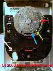
The photo at the top of this page includes arrows pointing to the controls and wiring terminals in a Honeywell combination fan and limit control type L4064B. We provide a guide to fan limit switches on warm air furnace heating systems: what is the fan limit switch, how to inspect and set its controls. Honeywell Combination Furnace Control type L4064 explained in detail.
This article series answers most questions about central heating system troubleshooting, inspection, diagnosis, and repairs. We describe how to inspect, troubleshoot and repair heating and air conditioning systems to inform home owners, buyers, and home inspectors of common heating system defects.
InspectAPedia tolerates no conflicts of interest. We have no relationship with advertisers, products, or services discussed at this website.
How to Choose the Proper Settings for a Warm Air Furnace Combination Fan & Limit Control Switch
 Here are the functions and and normal settings for the warm air heating furnace control switch such as the Honeywell Tradeline L4046 and 4046B combination fan and limit control:
As we explained above, the furnace fan limit control turns the furnace blower on and off at the proper times. Below we detail the functions and normal settings for five controls found inside this device.
Image: a photo of a 1970's era Honeywell L4046T fan limit control installed on a gas furnace showing common wiring connections on a gas furnace. A second pair of black wires is being used to control the furnace gas valve.
Watch out: when adjusting the set points on the combination furnace control be sure to hold the round faceplate dial steady with one hand while moving the sliding fingers or pointers in its face. Otherwise you may bend, strain, or damage the temperature sensing element (the bimetallic spring and related parts).
Bending the element could make the control fail to sense temperature accurately and thus could be dangerous.
Also do not "turn" the silver dial by hand to try to make the control turn on or off. This too can damage the control, making it unsafe.
The basics of how furnaces work can be read
and the key heating furnace components are introduced
at FURNACES, HEATING - home. This website discusses these systems and heating components in detail in articles listed at the end of each article.
If your heating system is not working properly,
see NO HEAT - BOILER - hot water heating systems
or NO HEAT - FURNACE- forced air heating systems
1. Furnace FAN OFF Setting
 The furnace combination fan and limit control FAN OFF setting (blue arrow in our photo at left) lets the furnace blower continue to run for an interval after the furnace burner has turned off, but will shut the blower off after the heat exchanger has been cooled down and the heat it contained has been sent to the occupied space.
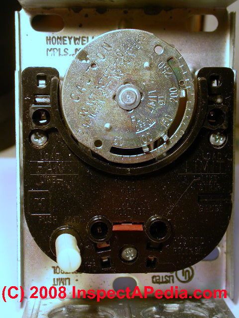
The FAN OFF setting is the left-most metal finger protruding through the round silver plate of the fan limit control. Move the FAN OFF setting lever to the temperature at which the fan is to stop in order to prevent sending cool air into the occupied space.
From the factory the FAN OFF finger is usually set to about 90 °F. Occasionally as high as 110 °F
At the end of a furnace-on heating cycle, after the gas or oil burner shuts down, the furnace blower will continue to operate for a time.
This continued fan operation achieves the following:
- The remaining heat from the hot furnace heat exchanger is salvaged and sent into the occupied space
- The furnace heat exchanger is cooled down more uniformly by the air flow over its surfaces in order to help reduce the chances of heat exchanger cracking
- The temperatures in the occupied space remain more even
2. Furnace FAN ON Setting
When an adequate warm temperature has been reached inside of the furnace warm air plenum chamber the FAN ON switch turns (green arrow in our photo at above left) on the furnace blower to deliver warm air to the occupied space.
The FAN ON setting on this control makes sure that the blower fan does not turn on too soon (even though the building thermostat has asked for heat) so that the furnace will not blow cool air into the occupied space. This setting also prevents the blower fan from cycling on and off too frequently during a heating cycle.
The FAN ON setting is the metal finger second from left-most, protruding through the round silver plate of the fan limit control.
This finger is set to a temperature range from a minimum of 20 °F above the FAN OFF set point, to a maximum f 30 °F below the LIMIT OFF set point.
From the factory the FAN ON is usually set to about 130 °F.
3. Furnace LIMIT OFF Setting
The LIMIT OFF indicator setting (red arrow in our fan limit switch photo at above left) is a safety control that will turn off the oil or gas burner if temperatures inside the warm air plenum exceed a safe level.
This is the highest temperature setting on a furnace combination control. It is set to the furnace warm air temperature at which this safety switch is to turn off the oil or gas (or other) burner or heat source.
On the Honeywell L4064B the LIMIT OFF is set to a temperature between 100 °F and 250 °F.
From the factory this setting out of the box is 200 °F.
If the temperature inside the supply plenum reaches the "high" limit set at the LIMIT OFF finger, the switch will turn off the oil or gas burner.
This condition may not ever happen under normal conditions with most hot air furnace systems - on those systems the burner continues to run all of the time the thermostat is asking for heat.
Watch out: The LIMIT OFF or "HIGH" or "MAX" on the furnace fan limit switch is a safety device.
In the unusual event that temperatures inside the supply plenum become too high, when temperatures reach the LIMIT OFF setting the fan limit
switch will turn off the burner to prevent damage to the furnace heat exchanger (from warping or cracking from excessive temperatures)
4. Furnace LIMIT STOP Setting
The LIMIT STOP control is an extra safety device to make it difficult for an amateur to set the LIMIT OFF to an unsafe or too-high temperature. This control setting could be changed by inserting a pen tip or similar object into the round hole visible in the LIMIT STOP plate near the right end of the temperature dial and slog on the silver plate of the fan limit control.
The LIMIT STOP is set at the factory to 200 °F. You should not change this setting as to do so maybe dangerous.
5. Furnace FAN ON Manual or "override" Switch
Fan override switch, also called a "manual fan switch" or "fan on switch" if present, is usually a white button that can be set to cause the furnace blower fan to run continuously or to run automatically driven by the temperatures sensed by the combination fan and limit control switch.
The fan override switch is indicated by the white arrow in our photograph.
FAN ON SWITCH Settings:
Manual-On furnace fan: Push the white fan override button "IN" to set the fan to its MANUAL position to force the furnace blower to run continuously. This setting can be used to move (and presumably to filter) building air through the heating duct system at any time of year.
Some experts opine that running the fan continuously will make heat in the building more uniform and more comfortable. (This will not be true in every building and for every heating system and in some cases can cause blowing of uncomfortably cool air into some rooms during the heating season.)
- Automatic furnace fan: Pull the white fan button "OUT" to the AUTO to cause the fan to cycle on and off automatically in response to temperatures sensed by and set on the fan limit control dial.
After completing these control settings be sure you test the combination fan and limit switch for safe and proper operation.
See FAN LIMIT SWITCH TROUBLESHOOTING for details.
There we discuss troubleshooting furnace blower fan operating problems such as a blower that runs continuously or one that turns on and off to frequently.
Reader Question: which way do we push or pull the fan switch to go between AUTOMATIC and MANUAL-ON
"(Pull out the button to force the fan to "always on". Push the white button back in to return the fan to automatic operation" - It seems opposite on the diagram you have.. have a look. It says "pull automatic". I'm pretty sure mine is the same unit. I'm having trouble with blower motor always staying on after heater runs... any ideas? Thanks! Rob - 10/17/12
Reply:
Rob, thanks for the suggestions; I have revised, corrected and also clarified the article above, adding photos, and tuning up the text. We welcome critique, corrections, or suggestions from our readers.
- PUSH the white button IN to force the fan to ON or MANUAL or always-running mode.
- PULL the white button OUT to put the fan back into AUTO mode - turning on and off under control of the switch and furnace temperature
Question: the White Rodgers 90-340 24VAC Isolation Relay
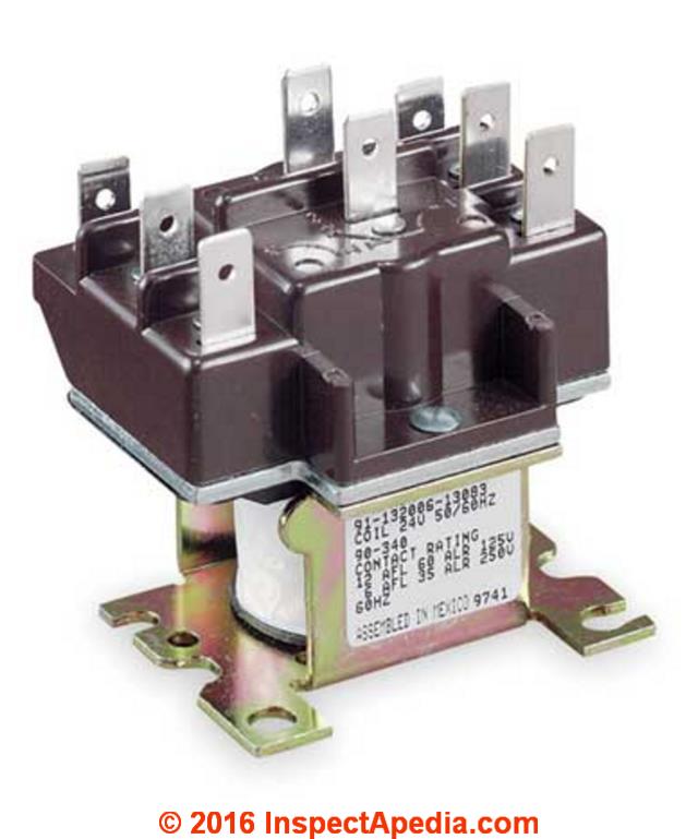
Shown above: White Rodgers 90-340 24VAC Relay switch, model 90-340. [Click to enlarge any image]
2016/09/16 Bob said:
I have older electric furnace with heat and ac. I replaced the sequencers last year and the fan isolation relay last week. the wiring was suspect before the repairs, I had to rewire the 24 volt wiring.
The only wire now I am wondering about is the 240v wire from the heat sequencer to the isolation relay.
The only problem I have is: only the high speed fan runs. the low speed fan does not run when heat is on, it continues to run the high speed fan. this is is fan auto and fan on.
What is the proper wiring from sequencer to fan isolation relay to have low speed fan for heat? I have high speed for ac and fan on as wired.
Reply:
For space we've moved this to a separate page.
Please see ISOLATION SWITCH WIRING
Useful Furnace or Air Handler Fan Limit Control Reference Resources
- Honeywell Corporation, Minneapolis, MN 55408. Honeywell has sales offices in all principal cities in the world and has manufacturing facilities in Australia, Canada, Finland, France, Germany, Japan, Mexico, Netherlands, Spain, Taiwan, United Kingdom, U.S.A. Honeywell Form Number 60-0450 7-75, residential division.
Honeywell's latest product data for this type of control can be found in English at http://customer.honeywell.com/Techlit/Pdf/69-0000s/69-0117.pdf - HONEYWELL L4064A-F,J,R,T,W,Y FAN AND LIMIT CONTROLLERS INSTRUCTIONS 2010 [PDF] (2010) - current instructions
- HONEYWELL L4064A-F,J,R,T,W,Y FAN AND LIMIT CONTROLLERS INSTRUCTIONS 1981 [PDF] (1981) - older instructions
- HONEYWELL L4064A-F,J,R,T,W,Y FAN AND LIMIT CONTROLLERS INSTRUCTIONS [PDF] (1985)
- HONEYWELL L4064B, L4064 R UNIVERSAL COMBINATION FAN & LIMIT CONTROLLERS MANUAL 2013 [PDF] (2013)
- HONEYWELL L4064B UNIVERAL FAN & LIMIT CONTROLLER SUPER TRADELINE INSTALLATION INSTRUCTIONS [PDF] (2006)
- HONEYWELL L6064 UNIVERAL TWO SPEED FAN & LIMIT CONTROL MANUAL [PDF]
- White Rogers 5D51-35, -78, & -90 FAN LIMIT CONTROL INSTALLATION INSTRUCTIONS [PDF]
The L4064T,W,Y ... have a bimetal heater switch which turns fan on approximately 20 to 90 seconds under normal conditions after the thermostat calls for heat. Fan turns off according to plenum temperature.
Reader Comments, Questions & Answers About The Article Above
Below you will find questions and answers previously posted on this page at its page bottom reader comment box.
Reader Q&A - also see RECOMMENDED ARTICLES & FAQs
On 2022-11-20 by InspectApedia (Editor) - universal replacement for the L4064 series fan limit controls
@Tom Lewis,
The Honeywell OEM Furnace 11" Replacement Combination Fan Limit Switch # L4064A3046 is sold by local heating suppliers, some plumbing suppliers, an online vendors of heating equipment, even amazon.
There is a universal replacement for the L4064 series fan limit controls.
at FAN LIMIT SWITCH INSTALLATION & WIRING
we provide also this
HONEYWELL L4064B, L4064R UNIVERSAL COMBINATION FAN & LIMIT CONTROLLER INSTALLATION MANUAL [PDF] (2017)
On 2022-11-20 by Tom Lewis
Where can I get a Honeywell limit switch for my oil furnace? L4064A3046-6-0409F
On 2021-12-17 by Inspectapedia Com Moderator - set the damper according to the manual for your wood stove
@Alfie,
If I understand correctly, since your alternate heat mode is electric with no concern about needing two different draft settings depending on which it source is in use.
You would set the damper according to the manual for your wood stove and that's probably model specific.
Can you tell us the brand and model of the stove so that we can look at its manual?
On 2021-12-16 by Alfie
I have a wood/electric furnace with 2 high/low limit switches, the fan limit switch is set at factory settings, but where do I set the wood thermostat/ damper motor at?
On 2021-11-30 by Inspectapedia Com Moderator - McQuay & Snyder HVAC manuals
@Travis,
On the following page, please take a look at the section named:
MCQUAY & SNYDER GENERAL HVAC MANUALS
On 2021-11-30 by Travis
I am looking for a manual for a snyder general furnance. Model # guh060a012in.
On 2021-10-29 by inspectapedia.com.moderator - Fan limit switches are widely available
@Jamiebizzak,
Fan limit switches are widely available from
- local plumbing and heating suppliers
- local HVAC service companies
- online vendors
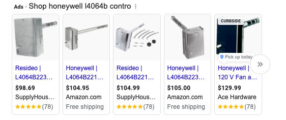
Simply type "Buy Honeywell L4064b control" into the search line of your web browser and you'll see a response like the one we show below.
Watch out: heating controls are critical safety devices - while their installation is not technically difficult, making a mistake or damaging the control (such as by manually turning the temperature control dial on your L4064b fan limit control) can make the heating system unsafe, risking fire, injury or worse. If you're not trained in safe and proper heating system controls and service it's best to use a trained HVAC service technician to do the job.
On 2021-10-29 by Jamiebizzak
Where can I buy a Honeywell L4064b limit control switch for a 1985 comfortmaker furnace?
On 2021-03-19 by Jim Navotney
My 1963 Moncrief furnace has a L4064 fan switch and it has 3 sliding fingers. Max limit, fan ON, and fan OFF. Max limit from the factory is 200 degrees which will most heat exchangers and can begin to melt some AC coil condensate trays
The maximum bonnet temperature on my data plate says 170 degrees so my limit is set at 165. And i found that i got maximum efficiency and comfort with the fan set to come on at 110 degrees and go off at 90 degrees.
Ideally you want the blower to come on as soon as possible to satisfy the thermostat sooner and waste less heat up the flue and go off as low as possible in order to not waste all the residual heat in the plenum and duct work.
I found that on the coldest day my furthest register had 80 degree air at fan off which is the minimum temperature to avoid feeling a cold draft.
On 2021-02-14 by (mod) - Honeywell L4064T Fan Limit Control details
Steve
Thank you for the interesting comment.
In the two (current 2010 and older 1985) IO manuals that we list above on this page for the Honeywell L4064 Fan Limit Controller instructions,
the company says:
The L4064T,W, and Y however, have a bimetal heater in the fan switch that turns the fan on approximately 20 to 90 seconds* after a call for heat begins.
Fan off is approximately 2-4 minutes after the call for heat ends.
The wiring example below is one of the details given by the company for the L4064T- model
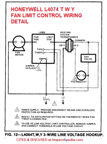
This chart of fan on and off times for the L4064T may also be helpful

On 2021-02-14 by Steve - The T suffix (L4064T) has the 2 additional black wires
The T suffix (L4064T) has the 2 additional black wires which run to the gas value, but they do not control the gas value, the gas valve controls the indoor (house) blower fan. When the gas valve is energized, to send gas to the burner, some of the 24V ac power goes from the gas valve solenoid to the Honeywell fan control, to energize the fan during the initial heat startup cycle.
This is from a Lennox Pulse G14 furnace, which heats up very fast so the indoor blower fan must start earlier before the regular thermostatic bimetal switch is triggered.
When the heating cycle stops and the gas turns off, those black wires are supposed to be de-energized to stop the artificial running of the fan, and the thermostat bimetal switch controls the fan.
As the air in the furnace plenum cools down due to the lack of flame and blower fan running, the dial turns and the finger shuts off the fan.
Not that on this model T, there is a middle finger which is not used, the first (lowest temp) finger controls the fan on and off.
I think the manufacturers keep most of these things secret because most people don't have the capacity to properly understand and service their appliances, and also because Lennox wants to keep their repair dealers fat and happy.
On 2020-09-22 - by (mod) -
Anon:
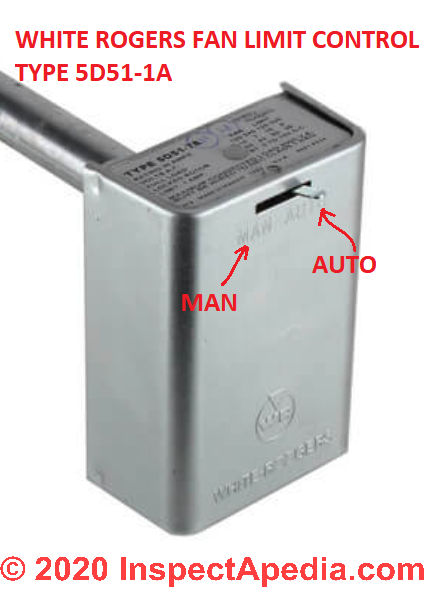
If by fan limit switch lever you're referring to the slide switch found at the top of the front of some fan limit controls, take a look at the embossed letters right on the switch cover. You'll see, as I illustrate below with a photo of a White Rogers fan limit control, that the words "MAN" and "AUTO" (or an equivalent) will appear.
"MAN" means "Manual" which means in this position you are forcing the fan to run or to turn ON
"AUTO" means that the fan will turn on or off depending on the temperature sensed in the heating plenum
On 2020-09-22 by Anonymous
The fan limit switch with the leaver instead of the button which way is over ride left or right
On 2020-09-18 by Anonymous
Anon
Let's start with a read of the article above on this page as we discuss how to set the fan limit control here.
On 2020-09-17 by Anonymous
How to set limited fan control switch on oil hot air furance
On 2019-06-09 - by (mod) -
Brian
The typical fan limit switch settings are getting on a page above.
please take a look and let me know if you have any questions about that text.
On 2019-06-09 by Brian
What should the fan limit switch be set at for the air conditioning and heating running Honeywell switch
On 2018-11-10 - by (mod) -
Herb the fan limit switch probably will look a lot like the unit shown in the article above and will use the FAN ON and FAN OFF and FAN LIMIT numbers given there.
If you can attach a sharp photo of your fan limit controller as well as of the Hobart furnace and any data tags on the equipment I can comment further.
On 2018-11-10 by Herb
Have a old Hobart furnace it runs and stop have heat what does the limit switch look like is it the one that said fan auto on it and r the universeal
...
Continue reading at FAN LIMIT SWITCH TROUBLESHOOTING or select a topic from the closely-related articles below, or see the complete ARTICLE INDEX.
Or see FAN LIMIT CONTROL SETTING FAQs - questions and answers posted originally on this page
Or see these
Recommended Articles
- AIR HANDLER / BLOWER UNITS - home
- FAN, AIR HANDLER BLOWER UNIT
- FAN MOTOR START CAPACITORS
- FAN, COMPRESSOR / CONDENSER UNIT
- FAN ENERGY INDEX FEI
- FAN LIMIT SWITCH - home
- FAN LIMIT CONTROL SETTINGS
- FAN LIMIT SWITCH INSTALLATION & WIRING
- FAN LIMIT SWITCH TROUBLESHOOTING
- FAN RUNS ONLY ON FAN-ON / MAN
- FAN WONT START
- FAN WONT STOP - LIMIT SWITCH
- FAN WONT STOP - THERMOSTAT SWITCH
- FURNACE BLOWS COLD AIR
- FURNACE FAN CYCLES AFTER HEAT
- FURNACE FAN CYCLES DURING HEAT
- FURNACE FAN STOPS EARLY
- ISOLATION SWITCH WIRING
- FAN MOTOR START CAPACITORS
- FAN NOISES, HVAC
- FAN ON AUTO MAN THERMOSTAT SWITCH
- FAN ON SWITCH ADDITION
- FAN WONT STOP - THERMOSTAT SWITCH
- UNDERSIZED RETURN DUCTS - not enough return air
Suggested citation for this web page
FAN LIMIT CONTROL SETTINGS at InspectApedia.com - online encyclopedia of building & environmental inspection, testing, diagnosis, repair, & problem prevention advice.
Or see this
INDEX to RELATED ARTICLES: ARTICLE INDEX to HEATING FURNACES
Or use the SEARCH BOX found below to Ask a Question or Search InspectApedia
Ask a Question or Search InspectApedia
Try the search box just below, or if you prefer, post a question or comment in the Comments box below and we will respond promptly.
Search the InspectApedia website
Note: appearance of your Comment below may be delayed: if your comment contains an image, photograph, web link, or text that looks to the software as if it might be a web link, your posting will appear after it has been approved by a moderator. Apologies for the delay.
Only one image can be added per comment but you can post as many comments, and therefore images, as you like.
You will not receive a notification when a response to your question has been posted.
Please bookmark this page to make it easy for you to check back for our response.
Our Comment Box is provided by Countable Web Productions countable.ca
Citations & References
In addition to any citations in the article above, a full list is available on request.
- In addition to citations & references found in this article, see the research citations given at the end of the related articles found at our suggested
CONTINUE READING or RECOMMENDED ARTICLES.
- Carson, Dunlop & Associates Ltd., 120 Carlton Street Suite 407, Toronto ON M5A 4K2. Tel: (416) 964-9415 1-800-268-7070 Email: info@carsondunlop.com. Alan Carson is a past president of ASHI, the American Society of Home Inspectors.
Thanks to Alan Carson and Bob Dunlop, for permission for InspectAPedia to use text excerpts from The HOME REFERENCE BOOK - the Encyclopedia of Homes and to use illustrations from The ILLUSTRATED HOME .
Carson Dunlop Associates provides extensive home inspection education and report writing material. In gratitude we provide links to tsome Carson Dunlop Associates products and services.
 | HOME | ABOUT | ASK a QUESTION | CONTACT | CONTENT USE POLICY | DESCRIPTION | POLICIES | PRIVACY | |
| © 2024 - 1985 Publisher InspectApedia.com - Daniel Friedman | |||||||||