
InspectAPedia® FREE Encyclopedia of Building & Environmental Construction, Diagnosis, Maintenance & Repair |
Question? Just ask us! InspectAPedia
|
 How Wire a Flair Thermostat
Flair Room Thermostat Wiring Connection Tables
- POST a QUESTION or COMMENT about heating, air conditioning, and heat pump thermostat installation and wiring
Thermostat wiring details & connections for the Flair thermostats. This article gives a table showing the proper wire connections for the Flair room thermostat used to control heating or air conditioning equipment.
Room thermostat installation & wiring guide: this article series explains the basics of wiring connections at the thermostat for heating, heat pump, or air conditioning systems.
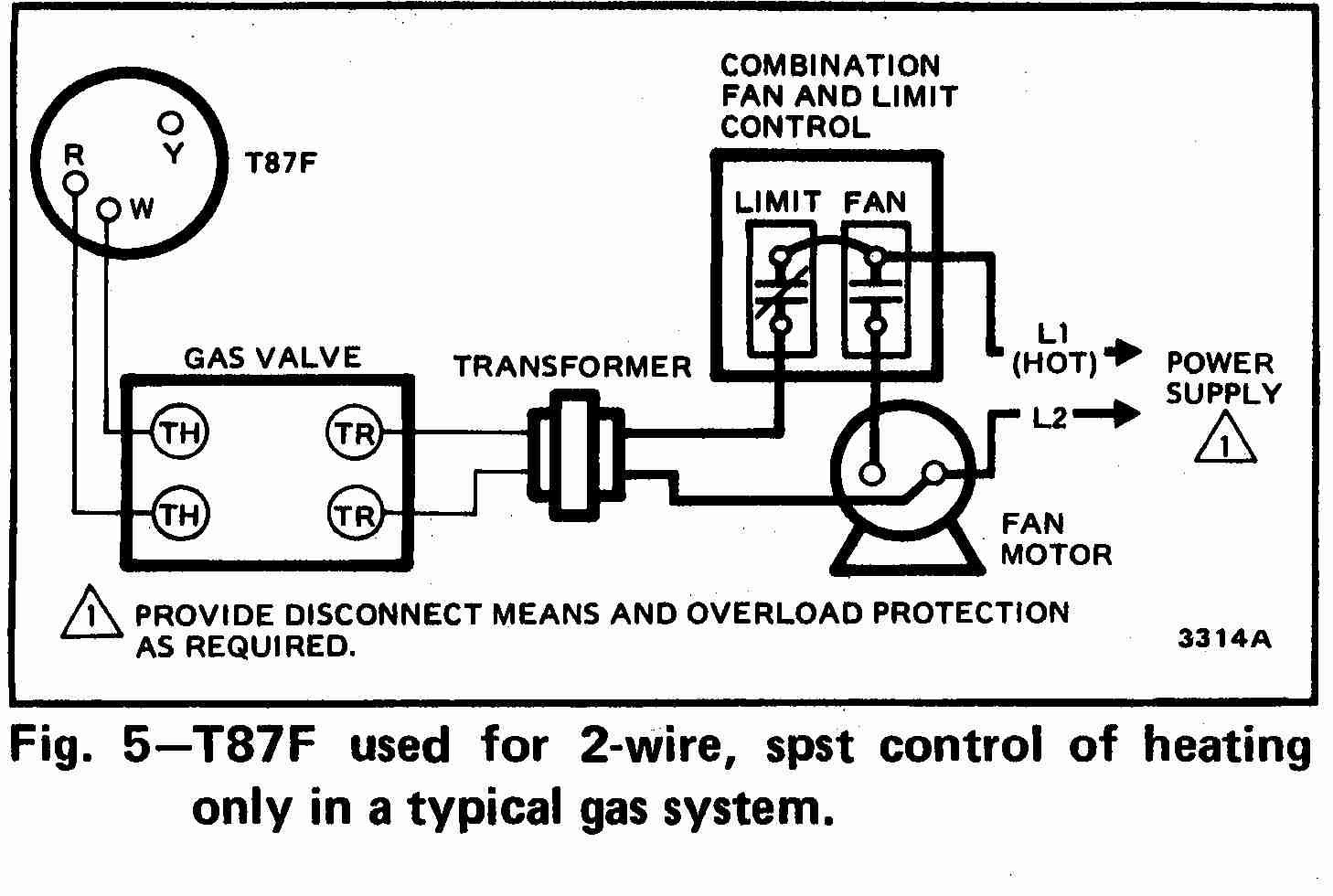
Our page top sketch, courtesy of Honeywell Controls, illustrates the wiring diagram for a traditional Honeywell T87F thermostat used for 2-wire single pole single throw control of heating only in a typical gas-fired heating system.
InspectAPedia tolerates no conflicts of interest. We have no relationship with advertisers, products, or services discussed at this website.
Flair Thermostat Wiring Instructions
2-Wire Flair APOV2 Thermostat wiring diagram
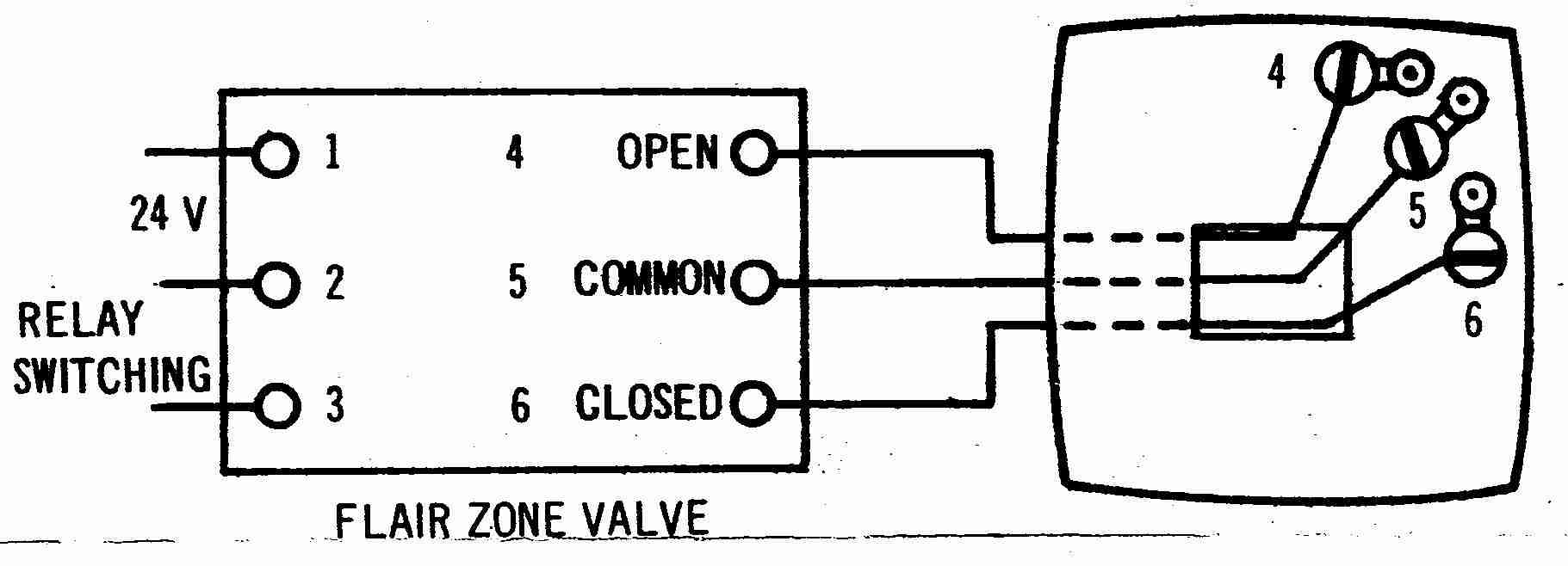
 at left the thermostat wiring diagram illustrates use of a Flair APOV2 wall thermostat in a typical 2-wire application controlling a heating appliance.
In this application the thermostat is acting as an spst (single pole single throw) switch to turn heat on or off, often by operating a zone valve.
When used to operate a zone valve the thermostat wires are connected to the zone valve terminals, not to a primary control on the heating boiler.
[Click any image or thermostat wiring schematic to see an enlarged, detailed version]
3-Wire Flair APOV2 Thermostat wiring diagram
Above the thermostat wiring diagram illustrates typical use of a Flair APOV2 wall thermostat in a 3-wire application controlling a heating appliance.
In this application the thermostat is acting as a single pole double throw (spdt) switch to control heating & cooling or in some zone valve applications.
Also see our table of Flair thermostat wiring connections found above at
- FLAIR 3-WIRE TYPE WALL THERMOSTATS - wiring instructions
How to Wire a typical Flair 3-wire type Wall Thermostat(3 wires found in use at the wall thermostat) Flair model ANOVO Thermostat fed from a Flair zone valve |
||
| As wire colors may vary, note the wire colors | Wire coming from Flair zone valve terminal (4) "Open" . Note 1. | |
| At the Flair zone valve and | Wire coming from Flair zone valve terminal (5) "Common" | |
| Match those colors to terminals at the thermostat as shown here | Wire coming from Flair zone valve terminal (6) "Closed" | |
Notes to the table above
1. The [Honeywell 5-2 Day Programmable Thermostat - RTH2300B1012] thermostat cannot be used if your old thermostat had and used any two of the following wires: R, RC, RH, 4 and V.[5]
We provide thermostat wiring connections for just about every type of residential heating or cooling room thermostat as well as a description of thermostat wiring color codes & conventions.
Reader Comments, Questions & Answers About The Article Above
Below you will find questions and answers previously posted on this page at its page bottom reader comment box.
Reader Q&A - also see RECOMMENDED ARTICLES & FAQs
Question: Replacing a round Honeywell T87 with a Digital Honeywell Thermostat
Hello - I am replacing a round Honeywell thermostat with a non-programmable digital Honeywell unit. I have a hot water system with multiple zones and with no air conditioning. There are three wires at the thermostat.
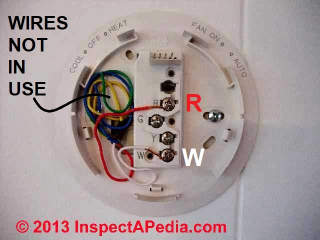
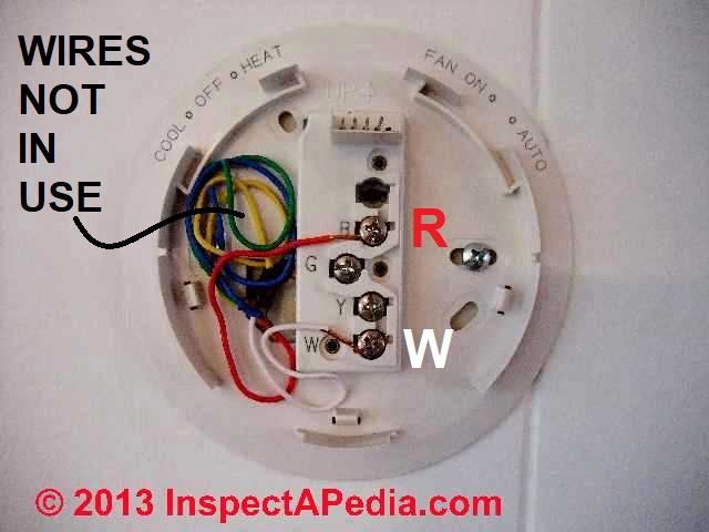
On the old round unit the red wire went to the R terminal, the white wire went to the w terminal and a green wire went to B terminal.
I hooked up the new stat the same way but it would not work. If I selected "fan on" instead of "fan auto" the zone would heat up but would not shut off (hot water kept flowing even if I selected a temp below room temp). Appreciate your help. - Patrick - 1/20/12
Reply:
Patrick, typically the three wire thermostat hookups would be exactly the same for the old and new thermostats.
For details of wiring a typical and simple digital Honeywell thermostat, see Honeywell 5-2 Day Programmable Thermostat - RTH2300B1012.
For help in understanding the wiring of your old thermostat,
see Three-Wire Honeywell Wall T87-F type Thermostat wiring and also
see Generic HVAC Thermostat Control Wiring Points
Question: Replacing a mercury thermostat with a digital unit
I am replacing an old mercury thermostat with a digital. my system is a heat pump. my neighbor gave me the digital, no instructions, no box. i'm trying to decide if this is even a heat pump compatible thermostat. on the therm it has c, g, rc, rh (which are linked by a black wire.) w, y, b, and o. coming out of my wall is, white connected on old therm w2, yellow connected to y, green conn g, black conn e, red to r, blue to b and bro to x. any help would be great. - Kurt 6/4/12
Reply:
Kurt, as you see in the examples at For help in understanding the wiring of your old thermostat,
see Three-Wire Honeywell Wall T87-F type Thermostat wiring and also
see Generic HVAC Thermostat Control Wiring Points. Many thermostat wiring setups are straightforward or "cookbook" but why not find the brand name on your thermostat and then you can obtain the installation instructions right from the manufacturer?
Also, Honeywell's thermostat replacement advice (and most likely that of all thermostat manufacturers) warns:
Watch out: MERCURY NOTICE: Do not put your old thermostat in the trash if it contains mercury in a sealed tube. Contact your local waste management authority for instructions regarding recycling and proper disposal.[5]
On 2016-06-14 by Johnny
Mod thanks again
Definitely mis communication I don't care about color of wires I care about the cross reference of the terminals
On my 3 wire stat only 3 terminals on the replacement stat 8 terminals
Can anyone tell me what terminal on the programmable stat R C W2 E Y O/B G L would the wire from the old stat terminal 4 labeled open go to then same for terminal 5 labeled common and lastly terminal 6 labeled closed
my 3 wire go from the stat to flair valve so not concerned about wire color it's the same corresponding numbered terminals on the valve
Thank you for any help
On 2016-06-13 - by (mod) -
Yeah, Johnny, we noted in the article above that in older Flair to Flair thermostat to zone valve or to other equipment wire colors in the field varied from standard.
Typically the installer will simply use a VOM to find which wires are carrying voltage - those form the "on" switch function that helps start to sort things out.
On 2016-06-13 by Johnny
Sorry for confusion we are looking at the flair thermostat cause that's what I have now and am looking to replace with the wr 1F72
I have the directions for the 1F72 BUT they don't cross reference back to what I already have the Flair valve
So I am looking for guidance to go from 3 wire flair stat to the new wr 1F72
On 2016-06-13 - by (mod) -
Sorry I'm getting lost here. Why are we looking at a Flair thermostat wiring diagram when you're wiring a White ROdgers 70-1F772 thermostat? Where you posted this question on another page I suggested a link to our White Rogers thermostat wiring page and on that page link to a PDF with wiring details for your thermostat.
On 2016-06-13 by Johnny
Terminals on 70 series are R C W2 E Y O/B G L
I have 4 blk, 5 wht, 6 red
On 2016-06-13 - by (mod) - if your thermostat is White Rodgers it's not a Flair unit
The standard color codes at https://inspectapedia.com/heat/Thermostat_Tips.php might help you out
But a WR 70 sounds like a White Rodgers thermostat. If so,
see THERMOSTAT WIRING WHITE RODGERS
On 2016-06-13 by Johnny
It the 70 series 1F72
Looking at above typical Flair 3-wire wall type thermostat wiring diagram. I cannot find any guide to help me find which terminals to use with programmable thermostat
I have WR 70 series model 1F772 please help I have 3 wires like above diagram termina
l 4 blk wire = open, terminal
5 wht wire = common, and
terminal 6 red wire = closed
Please help on which terminals to use on the programmable stat I have manual does not give corresponding terminals from my application
...
Continue reading at THERMOSTAT INSTALLATION STEPS or select a topic from the closely-related articles below, or see the complete ARTICLE INDEX.
Or see these
Thermostat Wiring & Installation Articles
- THERMOSTAT INSTALLATION STEPS - how to replace or install a new thermostat
- THERMOSTAT WIRING COLOR CODES & methods for identifying which thermostat wire is which if yours have lost their labels or have unclear color codes.
- THERMOSTAT WIRE CONNECTIONS detailed room thermostat installation & wiring guide for each heating or cooling system type and each thermostat brand / model
- COMMON WIRE at THERMOSTATS
- CONVERT LINE to LOW VOLTAGE THERMOSTAT
- THERMOSTAT WIRE CONNECTIONS - 2-WIRE like the T87F
- THERMOSTAT WIRE CONNECTIONS - 3-WIRE Red, White, Blue Wires
- THERMOSTAT WIRE CONNECTIONS - 4-WIRE Red, Yellow, Green, White
- THERMOSTAT WIRE CONNECTIONS - 5-WIRE Blue/Black, Red, White, Yellow, Green
- THERMOSTAT WIRE CONNECTIONS - 6-WIRE Red, White, Blue, Yellow, Green, Orange Wires
- THERMOSTAT WIRE CONNECTIONS - 8-WIRE Black, Red, White, Yellow, Green, Orange, Brown, Blue
- THERMOSTAT WIRE SORTING to ID R W B
- THERMOSTAT WIRING OPENING SEAL
- THERMOSTAT WIRING in PARALLEL / MULTIPLES
- THERMOSTAT WIRE TERMINAL ID CODES / FUNCTIONS - what are the R, W, and other thermostat wire terminals used for?
Suggested citation for this web page
THERMOSTAT WIRING FLAIR INSTRUCTIONS at InspectApedia.com - online encyclopedia of building & environmental inspection, testing, diagnosis, repair, & problem prevention advice.
Or see this
INDEX to RELATED ARTICLES: ARTICLE INDEX to HVAC THERMOSTATS
Or use the SEARCH BOX found below to Ask a Question or Search InspectApedia
Ask a Question or Search InspectApedia
Try the search box just below, or if you prefer, post a question or comment in the Comments box below and we will respond promptly.
Search the InspectApedia website
Note: appearance of your Comment below may be delayed: if your comment contains an image, photograph, web link, or text that looks to the software as if it might be a web link, your posting will appear after it has been approved by a moderator. Apologies for the delay.
Only one image can be added per comment but you can post as many comments, and therefore images, as you like.
You will not receive a notification when a response to your question has been posted.
Please bookmark this page to make it easy for you to check back for our response.
Our Comment Box is provided by Countable Web Productions countable.ca
Citations & References
In addition to any citations in the article above, a full list is available on request.
- [2] Thanks to reader S.R. for discussing loss of heat due to a thermostat wiring mistake, October 2010
- [3] Thank to Mr. Scott Meenen , G&S Mechanical Services , for providing some common thermostat wiring codes also found at Mr. Meenen's web page Malware Deleted 12/9/2014 . Mr. Meenan provides heating, heat pump, and air conditioning repair services in Maryland, Washington D.C., and northern Virginia. He can be contacted at 301-591-1646 or by Email to Malware Deleted 12/9/2014 - 10/2010. Quoting:
We service American Standard, Amana, Arco, Arco-Air, Bryant, Carrier, Coleman Evcon, Comfortmaker, Day/Night/Payne, Dunham-Bush, Fedders, Fredrich, Goodman, General Electric, Heil, Intertherm, ICP, Janitrol, Lennox (Armstrong, Johnson Air-Ease), Miller, Modine, Nordyne, Rheem/Ruud/Weatherking, Sears, Stewart Warner, Trane, Weather King, Williams, White-Westinghouse, Whirlpool, Weil Mclain, York, (Frasier Johnson/Borg Warner) and others. - [4] Azel Technologies Inc., P.O. Box 53138 10 Royal Orchard Blvd. Thornhill, Ontario, Canada L3T 7R9 Ph: 905-223-5567 Fax: 905-223-3778 Email: info@azeltec.com, Website: www.azeltec.com.
- [5] Honeywell Controls, the company wants you to use their contact form at this web page: http://www51.honeywell.com/honeywell/contact-support/contact-us.html
Honeywell Consumer Products, 39 Old Ridgebury Road Danbury, CT 06810-5110 - (203) 830-7800
World Headquarters, Honeywell International Inc., 101 Columbia Road, Morristown, NJ 07962, Phone: (973) 455-2000, Fax: (973) 455-4807 1-800-328-5111- Honeywell product model numbers & instruction Manuals: see http://yourhome.honeywell.com/home/Applications/FindYourModelNumber.aspx
- [6] White Rodgers Thermostats and HVAC controls,
Homeowner information: http://www.emersonclimate.com/en-US/brands/white_rodgers/Pages/wr-homeowner-info.aspx
Contractor information: http://www.emersonclimate.com/en-US/brands/white_rodgers/wr_contractor_info/Pages/white-rodgers-contractor-info.aspx
White Rodgers Product Catalog (don't misspell the company's name as White Rogers Thermostats) -
http://www.emersonclimate.com/Documents/thermostats.pdf - Thermostat Catalog - [7] White Rodgers 1F90 Low Voltage Digital Comfort-Set thermostat Installation Instructions, PN 37-3654, White-Rodgers Division, Emerson Electric Co., 9797 Reavis Rd., St. Louis MO 63123
- [8] "Automatic Oil Burner Controls - Thermostats", Domestic and Commercial Oil Burners, 3rd Ed., Charles H. Burkhardt, McGraw Hill, 1969 (and later editions), ASIN B0000EG4Y8
- [9] Thermostat wiring color codes & conventions, Thanks to reader " Helpful Pointers" Regarding 24V T, 10/7/2012
- [10] Domestic Central Heating Wiring Systems and Controls, 2d Ed., Raymond Ward, Newnes, ISBN-10: 0750664363, ISBN-13: 978-0750664363, Quoting from Amazon.com:
This unique A-Z guide to central heating wiring systems provides a comprehensive reference manual for hundreds of items of heating and control equipment, making it an indispensable handbook for electricians and installers across the country. The book provides comprehensive coverage of wiring and technical specifications, and now includes increased coverage of combination boilers, recently developed control features and SEDBUK (Seasonal Efficiency of Domestic Boilers in the UK) boilers ratings, where known.
In addition to providing concise details of nearly 500 different boilers fuelled by electric, gas, oil and solid fuel, and over 400 programmers and time switches, this invaluable resource also features numerous easy-to-understand wiring diagrams with notes on all definitive systems. Brief component descriptions are provided, along with updated contact and website details for most major manufacturers. - [11] Proliphix Corporate Headquarters [Website: proliphix.com] , 3 LAN Drive Suite #100, Westford, MA 01886 Phone: +1.978.692.3375 Toll Free (U.S.): 866-IP-LIVING (866.475.4846) Fax: +1.978.692.3378 - Sales: sales@proliphix.com Marketing: marketing@proliphix.com Customer support: support@proliphix.com http://www.proliphix.com/ - quoting from the company's website:
All Proliphix Network Thermostats come with our free Uniphy Remote Management Service. This unique offering lets you monitor and control your HVAC systems by simply pointing your Browser to our secure Proliphix Web Site. Enjoy the convenience of programming a thermostat from any location, using a simple graphical interface. No computer equipment or software is required. And since Proliphix takes care of the network configuration for you, you’ll be up and running in no time. We’ll even proactively monitor your thermostats and send you an immediate email or SMS message when an HVAC problem is detected. - [12] "Heating Control Handbook for the Installer and Service Man,Oil Burner, Gas Burner and Stoker Controls", Honeywell Corporation, March 1949 [copy on file as HoneywellControlsHandbookSA1399-2-1949.pdf] . Some of the controls discussed in detail here include the
- Honeywell T1 and T11A = Series 10
- Honeywell T21A (T2) = Series 20
- Honeywell T847A = Series 80
- Honeywell RA117A (RA1) = Series 10
- Honeywell LA101A = Series 10,
- Honeywell LA419A (LA4) = Series 40
- V155A = Series 10, V435A = Series 40, V575A = Series 50, V835A = Series 80
- [13] Trane TCONT800 Series Touch Screen Programmable Comfort Control Ownes Guide, American Standard, Inc., Troup Highway, Tyler TX 75711, January 2005, Telephone: Customer Service: 1-877-3381, website: www.trane.com
- Domestic and Commercial Oil Burners, Charles H. Burkhardt, McGraw Hill Book Company, New York 3rd Ed 1969.
- National Fuel Gas Code (Z223.1) $16.00 and National Fuel Gas Code Handbook (Z223.2) $47.00 American Gas Association (A.G.A.), 1515 Wilson Boulevard, Arlington, VA 22209 also available from National Fire Protection Association, Batterymarch Park, Quincy, MA 02269. Fundamentals of Gas Appliance Venting and Ventilation, 1985, American Gas Association Laboratories, Engineering Services Department. American Gas Association, 1515 Wilson Boulevard, Arlington, VA 22209. Catalog #XHO585. Reprinted 1989.
- The Steam Book, 1984, Training and Education Department, Fluid Handling Division, ITT [probably out of print, possibly available from several home inspection supply companies] Fuel Oil and Oil Heat Magazine, October 1990, offers an update,
- Principles of Steam Heating, $13.25 includes postage. Fuel oil & Oil Heat Magazine, 389 Passaic Ave., Fairfield, NJ 07004.
- The Lost Art of Steam Heating, Dan Holohan, 516-579-3046 FAX
- Principles of Steam Heating, Dan Holohan, technical editor of Fuel Oil and Oil Heat magazine, 389 Passaic Ave., Fairfield, NJ 07004 ($12.+1.25 postage/handling).
- "Residential Steam Heating Systems", Instructional Technologies Institute, Inc., 145 "D" Grassy Plain St., Bethel, CT 06801 800/227-1663 [home inspection training material] 1987
- "Residential Hydronic (circulating hot water) Heating Systems", Instructional Technologies Institute, Inc., 145 "D" Grassy Plain St., Bethel, CT 06801 800/227-1663 [home inspection training material] 1987
- "Warm Air Heating Systems". Instructional Technologies Institute, Inc., 145 "D" Grassy Plain St., Bethel, CT 06801 800/227-1663 [home inspection training material] 1987
- Heating, Ventilating, and Air Conditioning Volume I, Heating Fundamentals,
- Boilers, Boiler Conversions, James E. Brumbaugh, ISBN 0-672-23389-4 (v. 1) Volume II, Oil, Gas, and Coal Burners, Controls, Ducts, Piping, Valves, James E. Brumbaugh, ISBN 0-672-23390-7 (v. 2) Volume III, Radiant Heating, Water Heaters, Ventilation, Air Conditioning, Heat Pumps, Air Cleaners, James E. Brumbaugh, ISBN 0-672-23383-5 (v. 3) or ISBN 0-672-23380-0 (set) Special Sales Director, Macmillan Publishing Co., 866 Third Ave., New York, NY 10022. Macmillan Publishing Co., NY
- Installation Guide for Residential Hydronic Heating Systems
- Installation Guide #200, The Hydronics Institute, 35 Russo Place, Berkeley Heights, NJ 07922
- The ABC's of Retention Head Oil Burners, National Association of Oil Heat Service Managers, TM 115, National Old Timers' Association of the Energy Industry, PO Box 168, Mineola, NY 11501. (Excellent tips on spotting problems on oil-fired heating equipment. Booklet.)
- In addition to citations & references found in this article, see the research citations given at the end of the related articles found at our suggested
CONTINUE READING or RECOMMENDED ARTICLES.
- Carson, Dunlop & Associates Ltd., 120 Carlton Street Suite 407, Toronto ON M5A 4K2. Tel: (416) 964-9415 1-800-268-7070 Email: info@carsondunlop.com. Alan Carson is a past president of ASHI, the American Society of Home Inspectors.
Thanks to Alan Carson and Bob Dunlop, for permission for InspectAPedia to use text excerpts from The HOME REFERENCE BOOK - the Encyclopedia of Homes and to use illustrations from The ILLUSTRATED HOME .
Carson Dunlop Associates provides extensive home inspection education and report writing material. In gratitude we provide links to tsome Carson Dunlop Associates products and services.
 | HOME | ABOUT | ASK a QUESTION | CONTACT | CONTENT USE POLICY | DESCRIPTION | POLICIES | PRIVACY | |
| © 2024 - 1985 Publisher InspectApedia.com - Daniel Friedman | |||||||||