
InspectAPedia® FREE Encyclopedia of Building & Environmental Construction, Diagnosis, Maintenance & Repair |
Question? Just ask us! InspectAPedia
|
 Furnace Heat Exchanger Leak Tests
Heat Exchanger Testing & Safety Inspection Procedures & Standards
- POST a QUESTION or COMMENT about furnace heat exchanger leaks, cracks, damage, inspection & testing
Furnace heat exchanger inspection, troubleshooting, and leak testing guide: This heating system test article describes how to inspect furnace heat exchangers for leaks.
We compare and evaluate the reliability of all of the various furnace heat exchanger testing methods, we explain just how much leakage is "acceptable" by industry standards, and we conclude with recommendations for reliable heat exchanger testing and inspection.
Here photographs show clues indicating leaky, dangerous furnace heat exchangers. Furnace heat exchanger leak testing, A Complete List of Methods Used to Find or Test for Leaks in a Furnace Heat Exchanger.
13 leak detection procedures for furnace heat exchangers. Heat Exchanger Testing & Test Devices: Who's Right? Recommendations for reliable furnace heat exchanger testing procedures .
InspectAPedia tolerates no conflicts of interest. We have no relationship with advertisers, products, or services discussed at this website.
How to inspect a furnace heat exchanger for damage or leaks & carbon monoxide CO gas hazards
 Gas utility, gas furnace, & oil furnace service technicians use a variety of procedures in attempts to
identify potentially dangerous leaks in furnace heat exchangers.
Gas utility, gas furnace, & oil furnace service technicians use a variety of procedures in attempts to
identify potentially dangerous leaks in furnace heat exchangers.
Watch out: gas leaks at a furnace heat exchanger risk fatal carbon monoxide poisoning.
The procedures are typically used in response to service calls for
- odors
- fluttering burner flames
- suspected cracked heat exchanger
- sooted heat exchanger
- routine service
[Click to enlarge any image]
In a literature review and a survey of utilities conducted first in the 1980's, more than thirteen different procedures [for testing furnace heat exchangers for leaks] were identified. When used alone, many of these methods (described in this article) do not give reliable results, thus often more than one method is used. Some test methods are corrosive to the heat exchanger.
Others are performed under unrealistic conditions (such as increased pressure in the heat exchanger), or are so sensitive that they indicate leakage even in new heat exchangers.
Here we provide a catalog of the various methods used to check or test furnace heat exchangers for unsafe leakage of combustion gases - a potential safety hazard in buildings. These include the text from historical articles on methods used for testing furnace heat exchangers for leaks, and the allowable or standards for heat exchanger cracks, holes, leaks, or carbon monoxide hazards from such leaks.
Visual Inspection of the Furnace Heat Exchanger can Detect Some Leaks but Not All
Watch out: while visual inspection may discover obvious furnace damage and / or safety concerns, you should never rely on visual inspection alone
to determine the safety of a furnace heat exchanger.
Watch out: Dangerous carbon monoxide gas leaks, potentially fatal, can be present intermittently depending on variations in heating system operation and building conditions.
Also see CARBON MONOXIDE - CO
Also see BACKDRAFTING HEATING EQUIPMENT.
 More about carbon monoxide - CO - is
Those considering using instruments to test heat exchangers for leaks should
review RECOMMENDATIONS for GAS LEAK TEST INSTRUMENTS & gas detector tubes for indoor gas level tests.
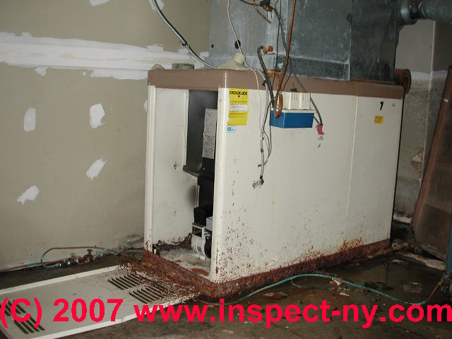
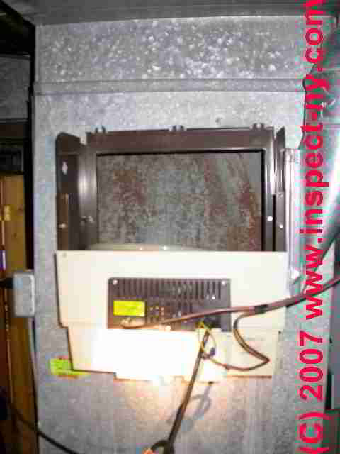
In response to a reader who wrote that they have a G14Q3, installed in 1988, Lennox Pulse Furnace and who was wondering if there are any visual inspections for signs of a defective heat exchanger we provide the furnace heat exchanger inspection suggestions described in this article.
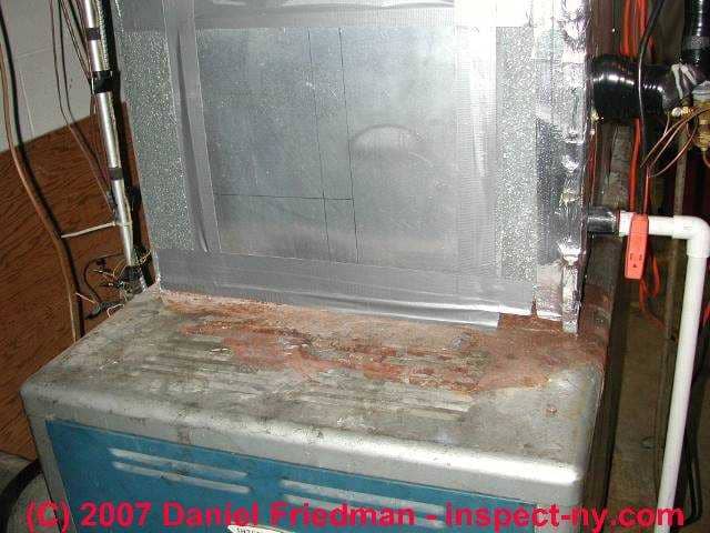
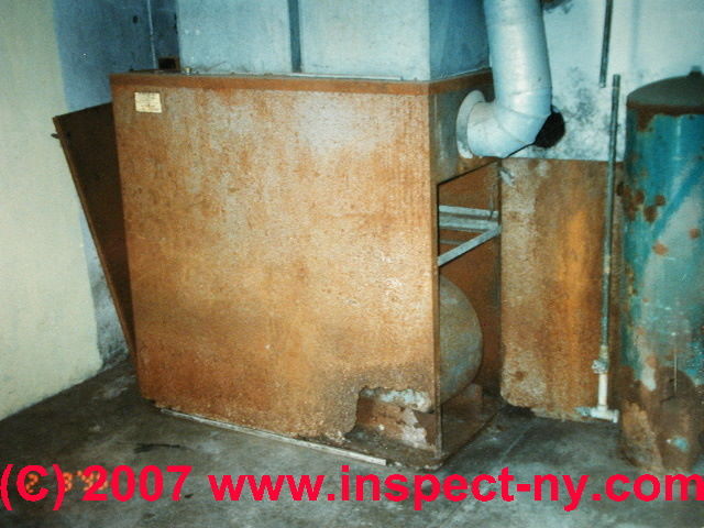
The photographs shown just above are two examples of rust and flame marks on a furnace that would be a basis for further inspection of the condition of the heat exchanger for cracks, rust perforation, or other unsafe conditions.
But heat exchanger leaks can occur in a variety of locations and parts, including:
- Cracks or open seams in the heat exchanger at various locations due to heat stress, mechanical stress, mechanical damage. Similarly, seams in the heat exchanger may have come apart or been improperly joined at manufacture, or the manufacturing process may have failed to fully crimp closed a heat exchanger seam
- Rust perforations in the heat exchanger such as those shown above or simply thinning of the heat exchanger wall (to 50% or less of original thickness) due to rusting.
Rust may occur due to condensate leaks onto the heat exchanger from an air conditioner coil, from humidifier leaks, or simply from location of the furnace in a damp or wet location. - Mechanical holes in the heat exchanger, for example due to lost or loose screws, or cleanout ports that were not closed properly or were lost during cleaning
- Gasket or sealant leaks: other writers also cite these heat exchanger leaks: broken crimped rings, broken or leaking heat exchanger furnace seals or gaskets, including cemented seals
Inspection Points & Tests for Furnace Heat Exchanger Damage & Leaks
 The following is a catalog of all known methods for testing residential heating furnace heat exchangers for dangerous flue gas or carbon monoxide leaks. Contact us to add methods or critique. The list is arranged alphabetically rather than in any order of recommended procedure.
Watch out: SAFETY WARNING: Any evidence of furnace heat exchanger damage or of carbon monoxide or flue gas leaks should be taken seriously and those heating systems should be immediately checked by a professional.
Current industry standards for furnace heat exchanger leak testing procedures & results are given
at HEAT EXCHANGER LEAK TEST STANDARDS
- #1 Combination methods to check for heat exchanger leaks:
DeWerth's Three Step Method for Detecting Unacceptable Flue Gas Leakage from Furnace Heat Exchangers describes a combinatorial approach to inspecting furnace heat exchangers for unsafe flue gas or carbon monoxide leakage.
See HEAT EXCHANGER LEAK 3-STEPS - #2 Dye test: Heat exchanger test using a penetrating dye
such as Magna Flux: liquid dye (red or fluorescent dye) is sprayed over an area of the heat exchanger expected of leakage and the interior is inspected for evidence of the dye. If using a fluorescent dye the heat exchanger is examined using a UV or "black" light.
Detail: a spray can of fluorescent solution is marketed which is sprayed into the heat exchanger with a suspected leak and penetrates even the finest crack. Then the crack is detected using an ultraviolet light; however the heat exchanger must be accessible for close examination of all surfaces.
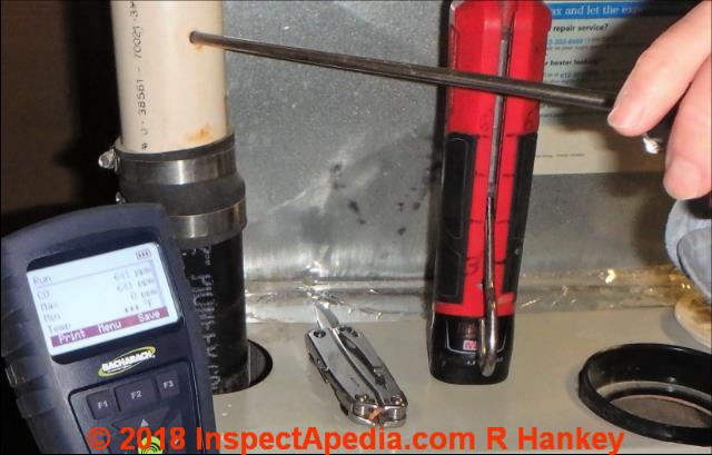
Above: Minnesota home inspector Roger Han key using a combustible gas analyzer to check for CO in the exhaust flue of a Tempstar condensing furnace suspected of having heat exchanger damage.
Details are at CONDENSING GAS FURNACE INSPECTION & TESTS.
- #3 Gas-Detection Instrument tests: Heat Exchanger Leak Detection Instruments measuring flue gases or carbon monoxide (CO)
in the supply air plenum, in the exhaust flue, or in the ambient environment around the furnace:
A flue gas leak or carbon monoxide detection instrument such as the TIF8800 combustible gas analyzer or other hand-held gas detectors,
other CARBON MONOXIDE TESTING METHODS, or a home carbon monoxide detector can detect the presence of carbon monoxide or heating system combustion gases (even without carbon monoxide in the case of the two references above),
But the absence of detection of flue gases or carbon monoxide at any particular time cannot be taken as a guarantee that the heat exchanger is not damaged and leaking.
Similar tests check changes in the CO level or for oxygen levels greater than 0.5% in the flue.
Watch out: testing for flue gases or CO as a sole method for testing for heat exchanger leaks is unreliable. Depending on whether or not the blower fan is operating, where the leak is located, and burner adjustment, the heat exchanger may have a leak that goes undetected by instruments. Be sure to check measurements both before and after the blower fan has begun to operate.
Depending on where the damage is on the heat exchanger, heat exchanger tempearture, and on whether or not the furnace supply air blower fan is operating, a leak may be present but remain undetected.
- See GAS DETECTION INSTRUMENTS - guide to toxic gas measurement instruments
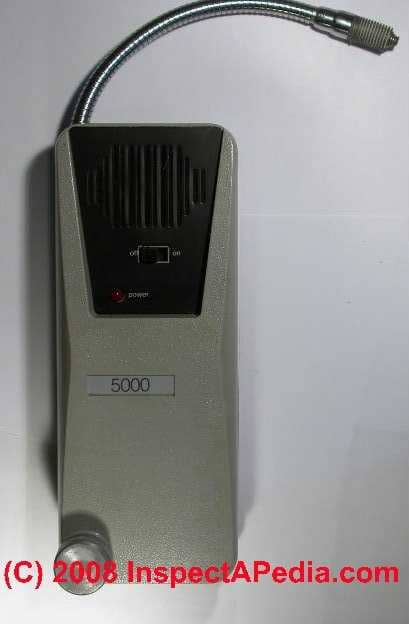
- See TIF 5000 GAS DETECTOR - guide to using TIF5000 gas detector for refrigerant gases - used as a trace gas to check for heat exchanger leak - no longer recommended nor permitted where discharge of refrigerants to the environment is a possibility.
- See TIF 8800 GAS DETECTOR - guide to Using the TIF 8800 combustible gas analyzer used to screen for flue gas leaks, carbon monoxide, similar hazards.
- TIF 8800 FIELD TEST describes field experience using this device.
- #4 Knowledge-based heat exchanger tests:
- Known causes of heat exchanger damage: in addition to the possibility of leaks and rust damage we've already discussed, other
conditions can make a visible or hidden heat exchanger crack or opening more likely to have occurred.
These include evidence that the system was dropped or damaged during shipment or installation, or knowledge of or evidence of overheating, such as the furnace's burner having been forced to operate past the normal high temperature limits of a fan limit switch.
We encountered this last damage after an inspector, knowing that once the blower comes on any furnace gas leak may be diluted or even reversed in direction, wired the furnace's gas burner to keep operating past the normal high limit on that safety control, so that s/he would have a longer period to test the system for leaks. - Known problem furnace or heat exchanger brands: Some heating furnace brands and models have become known to have frequent or specific safety concerns.
If your furnace model has been recalled or has had a safety warning issued concerning it that information can often be found by searching the US Consumer Product Safety Commission's website or by asking your local heating contractor to check that information for you. Some examples of heat exchanger and carbon monoxide warnings about heating products include:- CONDENSING GAS FURNACE INSPECTION & TESTS - Tempstar® Furnace reverse air flow at combustion air inlet
- LENNOX PULSE Furnace Safety Problems, Recall, Inspection, Advice
- WEIL MCLAIN MODEL GV Gas Boiler/gas valve CPSC recall/repair
- GOODMAN FURNACE High Temperature Plastic Vent HTPV safety recall US CPSC notice
- HOME HEATING SYSTEM Should Be Checked [for proper venting and for CO Carbon Monoxide Hazards - DJF]
- Known causes of heat exchanger damage: in addition to the possibility of leaks and rust damage we've already discussed, other
conditions can make a visible or hidden heat exchanger crack or opening more likely to have occurred.
- #5 Pressure changes: Heat exchanger test measuring pressure changes:
the magnehelic gauge test.
The heat exchanger is sealed, a special gauge connected to the unit at a pressure sensing port, and the blower is operated. Gauge reading changes can indicate that the blower is pressurizing (leaking into) the heat exchanger.
Details: see FURNACE HEAT EXCHANGER PRESSURE MEASUREMENTS FOR LEAK DETECTION
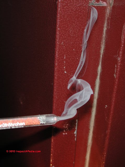
- #6 Smoke tests: Heat exchanger test using a chemical smoke generator or a "smoke bomb": a smoke bomb is lit inside the heat exchanger and the inspector watches for smoke escaping into the plenum. Properly used smoke bombs can be a very sensitive test as the smoke bomb pressurizes the heat exchanger with smoke when it ignites.
Similar to the smoke bomb, but without the risk of placing a burning device into the heat exchanger is use of an external smoke source (chemical) that is used to blow smoke into the heat exchanger.
We have read that some technicians used a lit piece of roofing felt inside the heat exchanger as a smoke source. We do not recommend this method - it is unreliable, but for other applications such as tracing air leaks smoke pencils can be quite useful.
See SMOKE TESTS & SMOKE BOMBS for HEAT EXCHANGERS for details - #7 Trace Gas test: Heat exchanger test using special gases:
AGA has described a test gas mixture of nitrogen/methane inserted into a plugged heat exchanger (also may require disassembly in some cases). There are other test gases that have been or continue to be used to test furnace heat exchangers for leaks.
One test procedure used by some practitioners is to release a small amount of carbon monoxide (CO) in the hot heat exchanger and then check for high concentrations of CO in the circulating air stream. The detector needed for this method is expensive and the use of CO is dangerous. Freon has been used as a tracer gas with a halogen leak detector.
In our OPINION a more sensible test gas and one that is more-widely used, is a refrigerant or freon gas released in the combustion side of the heat exchanger and if the halogen leak detector senses halogens in the circulating air stream a leak is present.
Watch out: A problem with this method is phosgene gas (a deadly poison) can be generated if the freon passes through a flame. Also, freon is heavier than air.
A less sophisticated gas test burns a small quantity of sulphur inside the heat exchanger while the inspector looks (subjectively?) for a sulphur odor in the living area, rising through the ductwork. [Not recommended.]
More reasonable and safe is the use of refrigerant gases and a halogen leak detector such as
the TIF 5000 GAS DETECTOR - a very sensitive instrument.
Also see REFRIGERANT LEAK DETECTION. Refrigerant gas as a tracer gas if used to check for heat exchanger leaks is no longer recommended nor permitted where discharge of refrigerants to the environment is a possibility. - #8 Visual inspection
of the heat exchanger for cracks: It is possible in some cases to see a damaged heat exchanger by spotting Cracks in the steel, discoloration, or soot. We illustrated and discussed visual inspection of heat exchangers just above.
Inspect for Common heat exchanger leak, crack, or rust points:
that should be included in an inspection include cracks at welds, seams, and on certain models, a heating service technician may know that defects have been found at a particular location.
HEAT EXCHANGER VISUAL INSPECTION LIMITATIONS [below in this article] explains that visual inspection alone is not enough to assure that a heat exchanger is not leaking
Prach (1993) points out that in a great many furnace installations it may be impossible to inspect all sides of the equipment as it may be obstructed by walls, ceilings, or adjacent appliances.
Only by complete disassembly would it be possible to make a "complete" visual inspection of the heat exchanger, and even in that case, some areas of the heat exchanger may be visually inaccessible simply because of the design and shape of the heat exchanger itself. [0]
See CONDENSING GAS FURNACE INSPECTION & TESTS for an example of visual inspection for leaks at a condensing gas furnace.

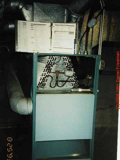
- #9 Extending the heat exchanger visual inspection with light and mirror:
One can try with a flashlight and mirror to extend the total area that can be seen above the Burner itself (with the burner off of course).
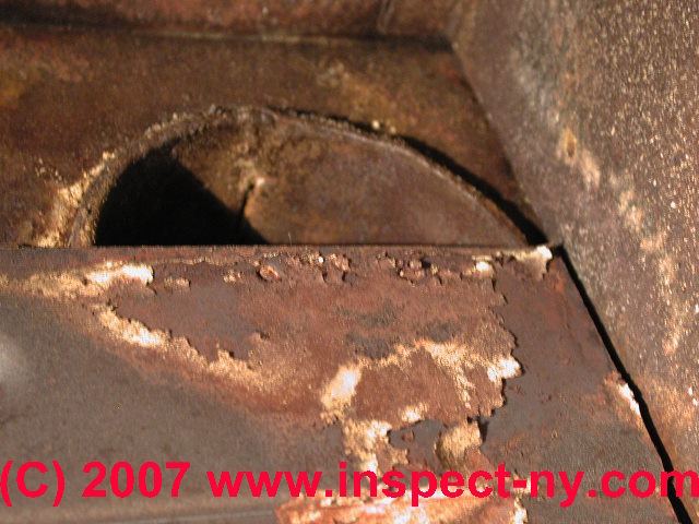
This photograph shows a significant hole in an oil fired heat exchanger. This damage was visible through the inspection door above the oil burner on the front of the furnace.
Using a telescoping mirror and flashlight one can inspect most of the interior of most oil fired furnace combustion chambers and most of the interior of the simple can-type oil fired furnace heat exchangers. But don't forget to use the other inspection methods discussed in this article.
- #10 Extend the heat exchanger inspection by examining from the supply air plenum:
One can also often see the top section of a heat exchanger by inspecting it through an opening in the Supply air plenum (in an up-flow system).
- #11 Indirect heat exchanger inspections
signs of causes of heat exchanger damage:
One might inspect "indirectly" by observing external evidence that indicates a risk of heat exchanger damage, such as exposure of the furnace to wet conditions
or FLOODING CONDITIONS [image], evidence of water leaks onto or into a furnace heat exchanger
(say from a HUMIDIFIER mounted above the heat exchanger [image],
or a plumbing leak onto the system,
or from an air conditioning CONDENSATE LEAK [image],
or an air conditioning
system DRIP TRAY LEAK [image] that may have sent water onto a heat exchanger leading to rust perforation. - #12 Direct visual inspection of the furnace for external signs of improper operation:
Example: see the visual inspection steps and use of a finger or tissue paper to check for reverse air flow at a condensing gas furnace air inlet, described by Roger Hankey
at CONDENSING GAS FURNACE INSPECTION & TESTS - #13 Direct visual inspection of the heat exchanger using a powerful flashlight;
but keep in mind that it virtually impossible to see all, or often even most of the heat exchanger during this type of inspection.
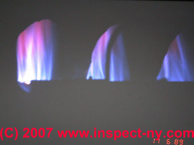
- #14 Inspect for Heat Exchanger Leaks by Evidence at the furnace burner - flame test:
for evidence of a heat exchanger crack or leak by watching for a change in flame pattern or color when the furnace blower just starts to operate.
Sit (not too close) where you can see the gas flame on a gas-fired heating furnace, then have someone turn up the thermostat to cause the furnace to start. Normally the burner will ignite and burn for a time (seconds to a minute or so) before it is warm enough for the fan limit control to turn on the blower fan.
When you hear the furnace blower fan start to operate be especially alert for a change in the color or pattern of the flame at the furnace's gas burner. (You can't to this test with an oil fired heating furnace).
If the flame pattern suddenly jumps, wavers, or changes color this is a strong suggestion that the heat exchanger is damaged. In the photograph we show inconsistent gas flame patterns at a gas fired heating furnace - additional inspecting and testing for safety were needed. - #15 Special flame test: to check for heat exchanger leaks
makes use of a chemical sprayed into the blower compartment while the burner is operating. If the blower is sending air into the heat exchanger the flame changes color. (VAPO HEAT HT-1Q. )
- #16 Water spray test: Heat exchanger water spray test:
(requires disassembly of the furnace) - the heat exchanger exterior is sprayed with water or a soap solution and its interior is examined for water entry
Visual Inspection of the Furnace Heat Exchanger Alone is Unreliable for Detecting Furnace Heat Exchanger Leaks or Damage
One of the most common methods used is a visual inspection of the heat exchanger with a strong light.
The serviceman must then make a judgment as to whether any cracks or holes he finds are large enough to warrant replacement of the furnace. Generally any fault is reason for recommending that the home owner obtain a second opinion of the need for replacement of a heat exchanger.
Given that a lot of the heat exchanger surface simply cannot be seen without completely disassembling the system, we would not rely on a visual inspection alone to decide if a system was damaged or not. There are other Tests using pressure testing or more commonly, tracer gas testing, that are more reliable.
Relying on gas detection instruments: Relying on gas detection instruments alone, without a visual inspection of the system is also dangerous and can falsely indicate that no problem in present when in fact the heating system is unsafe.
We discuss the reasons for this
at GAS DETECTOR WARNINGS - about relying on instruments for detection of hazardous gases in buildings.
Install CO detectors in buildings, as well as smoke detectors. Ultimately the combination of expert inspection, testing, and the use of carbon monoxide detectors and smoke detectors will make a significant improvement in the safety of any home heating system.
Smells and odors in the building could be an indicator of heat exchanger leaks -
Chemical Smoke Tests of Furnace Heat Exchangers
The American National Standards for Gas-Fired Central Furnaces (Z21.47-1978)
outlines a test method using a fuming or smoking material such as titanium tetrachloride.
The material is introduced into the combustion chamber, and if combustion products are discharged through door cracks or other openings, their presence will be revealed by observing the smoke. A drawback to this method is that titanium tetrachloride is very corrosive.
Another widely-used procedure involves spraying a sodium salt solution into the burner flames and checking the circulating air stream with a propane torch for the presence of sodium ions. [Detection of Cracked Heat Exchangers in Warm Air Furnaces , J.F. Wunderlin, Wisconsin Gas Co., GV-6, June 1978.]
If the blue flame of the torch turns yellow, this indicates the presence of sodium ions and a leak. As the solution is sprayed into the burner flame, visual inspection of the heat exchanger surface below the burner port is needed.
If a solution of sodium chloride (table salt) is used, corrosion of the heat exchanger can be accelerated. Sodium bicarbonate salt solutions, on the other hand, are non-corrosive. The drawbacks to the sodium ion tracing method are that dust in the air can be mistaken for the sodium ion and acceptable leakages may be detected as the test is very sensitive.
A procedure similar to the sodium ion tracing is to trace the lithium ion, with the same drawbacks.
All of these methods have some undesirable drawbacks. The ideal method for detecting the leakage of flue gases into the circulating air stream would not be harmful to the furnace components of the home environment, would be performed under realistic operating conditions, and would not detect small amounts of acceptable leakage.
Smoke Bombs for Heat Exchanger Tests
The use of smoke bombs is the second most common practice. With the flue outlet and burner access opening blocked a smoke bomb or candle is ignited in the heat exchanger.
Observations for smoke are then made in the circulating air side of the heat exchanger. When the bomb explodes a positive pressure is created inside the heat exchanger forcing the smoke out of very small cracks.
This makes the test very sensitive. Precautions are also needed with this method so the smoke does not get into the house where it may stain certain paints, fabrics, and tiles.
An air analysis test may be used in addition to the smoke test. This test detects combustion products in the circulating air stream as an indirect indication of heat exchanger cracks. If high readings are obtained there is no doubt that the heat exchanger has a crack or fault.
With slight increases a more thorough examination of the heat exchanger may be required. The drawbacks of this method are that it is complicated and time consuming to perform. Also the detection device is expensive.
Editor's note: See Matzen and other articles [below] for an evaluation and survey of this equipment. Significant to Matzen et al, DeWerth does not say these tests are necessarily invalid. Odorants, such as sulphur candles and oil of wintergreen have been used for detecting leaks.
A small quantity of the odorant is introduced into the combustion side of the heat exchanger; the hot air registers in the house are then checked for the characteristic odor. Any odor in the circulating air would indicate a heat exchanger leak.
With the sulphur candle this test can be quite reliable, but very unpleasant smelling. The wintergreen is more pleasant, but the odor clings to the serviceman's hands and clothes, making the test unreliable.
See SMOKE PENCIL / SMOKE GUN SOURCES.
Furnace Heat Exchanger Pressure Measurements for Leak Detection
The pressure drop across the furnace heat exchanger surface has a significant effect on the tendency of flue gases to pass from one side of the exchanger to the other. Only if the flue gas side is more positive than the circulating air side will there be a tendency for flue gases to leak into the circulating air through any cracks or corrosion holes in the heat exchanger.
In order to determine the actual operating pressure inside and outside the heat exchanger, measurements were made with four furnaces with typical heat exchangers. ["A Simple Test That You Can Use to Check a Furnace for Leaks," American Artisan, September 1966.]
Two of the furnaces were equipped with atmospheric burners, one with an induced draft system, and the fourth with a power burner. Flue gas pressure taps were attached at two-inch intervals up the side of the heat exchanger from the burner port to the flue outlet. Circulating air taps were located adjacent to the flue gas taps.
Pressure measurements were taken with and without the circulating air blower in operation. The results showed that with atmospheric burners the average pressure on the flue gas side with the burners operating is about 0.02 inch water column (w.c.).
The average pressure on the circulating air side of the heat exchanger is 0.3 inches w.c. when the blower is operating. Thus the air side of the heat exchanger is more positive than the flue gas side when the circulating blower is on. If there were a hole leakage would be from the air side to the flue gas side.
When the blower is off the air side pressure is less positive than the flue gas side and leakage would occur from the flue gas side to the air side. This condition exists only during the short heat up period before the blower starts.
An induced draft system has a negative pressure of about 0.2 inch w.c. or less on the flue gas side of the heat exchanger at all times. The flue products are drawn through the combustion chamber causing the flue gas side to always be under a negative pressure. A positive pressure on the air side of the heat exchanger, caused by the circulating air blower, further insures that the flue gases stay in the combustion chamber.
With a power burner system the flue gas side of the heat exchanger must have a positive pressure of as much as 0.4 inch w.c. Thus, the pressure on the flue gas side is more positive than the air side, whether the circulating air blower is on or off. The only exception is the top of the heat exchanger where the circulating air blower may impinge directly onto the heat exchanger.
Air side pressure would be more positive than the flue gas side at these points. If there were a hole or crack, flue gases would leak into the circulating air stream at all times except if the hole or crack were at the top of the heat exchanger.
Table 1 summarizes the various systems and the leakage potential due to the pressure drop across the heat exchanger. In a furnace with atmospheric burners flue gases could only leak into the circulating air system if there were a hole or crack during the time the blower was not operating.
Induced draft furnaces would not allow any leakage through the heat exchanger as they operate under a negative pressure. A power burner system is more critical in that the flue gas side of the heat exchanger is always more positive than the circulating air side when the furnace is operating. Thus, if there were a hole or crack flue gases could leak into the circulating air stream.
This analysis of flue gas leakage based on the pressure difference across the heat exchanger is true for relatively small holes. For heat exchangers with large perforations flue gases may leak regardless of the pressure differential. Large perforations would be detected by visual observation of the heat exchanger or by the flame pattern. No further test procedure would then be needed.
Test methods should not subject the heat exchanger to abnormally high pressures, and should not detect insignificant leakage which may occur from pin holes in welded seams or other manufacturing imperfections.
Current Standards & Procedures for Residential Furnace Heat Exchanger Inspection, Testing
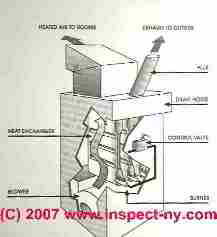
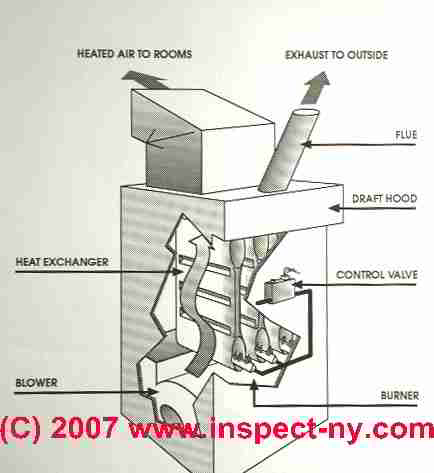
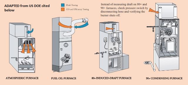 Illustration: adapted from "Combustion Appliance Safety & Efficiency Testing", U.S. DOE, cited below. [Click to enlarge any image]
- AGA mixed gas test method for heat exchangers: see http://www.aga.org/pdf/publicinfo/co...facts8612b.pdf also see the gas test kit available from http://www.testproductsintl.com/gas.html [dead links in 2018 - Ed.]
- American Gas Association, Furnace Heat Exchanger Leak Test, Source:
http://www.aga.org/NR/rdonlyres/A156C36A-9324-4978-91B4-E78DB63DAD7D/0/8612FURNHEATEXCHNGLEAKTEST.pdf
[dead links in 2018 - Ed.]
Included these three steps:
Step 1 Visual inspection, Step 2 Burner flame deviation test. Step 3 injecting a nitrogen/methane gas mixture into the burner chamber.
The heat exchanger outlet of the heat exchanger is plugged and a combustible gas detector is used to check for gas leakage on the exterior of the heat exchanger. A detailed fact sheet on the AGA test procedure is of the heat exchanger. - AHRI, INDUCED-DRAFT FURNACE HEAT EXCHANGER INSPECTION PROCEDURE [PDF], AHRI, Air-Conditioning, Heating, and Refrigeration Institute, 2111 Wilson Blvd, Suite 500
Arlington, VA 22201 USA, Tel: (+1) 703-524-8800,
Canada: AHRI, 2350 Matheson Blvd. East, Suite 101, Mississauga, ON L4W 5G9 Canada,
Email: bteferi@ahrinet.org, Website: http://www.ahrinet.org/Home, Fact Sheet, Excerpts:
Despite the excellent safety record of gas furnaces, there have been infrequent reports of gas furnace heat exchanger problems.
To address these situations, an industry-accepted procedure known as the “Three-Step Method for Detecting Unacceptable Flue Gas Leakage from Furnace Heat Exchangers” has been used since the early 1980's to conduct field inspections of gas-fired furnace heat exchangers.
Though this procedure has been effective for testing heat exchangers in natural draft furnaces, its effectiveness for testing heat exchangers on induced-draft furnaces that maintain a significant negative pressure within the heat exchanger has been questioned.
Though it is unlikely for an induced-draft furnace to leak flue products from the heat exchanger to the circulated airstream, a new test procedure has been developed that enhances the existing three-step methodology to make it more applicable, reliable and repeatable for the inspection of induced-draft furnace heat exchangers.
Five-Step Method [elaborated in this document] includes
1. Look for flame disturbances
2. Measure CO levels in the airstream
3. Measure CO levels in the flue pipe
4. Verify Proper Installation
5. Visually Inspect Heat Exchanger - AHRI 2009 GUIDELINE FOR INDUCED DRAFT FURNACE HEAT EXCHANGER INSPECTION [PDF] (2009) Air-Conditioning, Heating, and Refrigeration Institute, Air-Conditioning, Heating, and Refrigeration Institute (AHRI) 2311 Wilson Blvd, Suite 400 Arlington, VA 22201 USA
- Air Heaters, ASME PTC 4.3-2017, available from ANSI, ANSI Customer Service,
Email: info@ansi.org Tel: 1.212.642.4980 Website: https://webstore.ansi.org
Abstract:
This Code provides procedures for conducting performance tests of air heaters to determine: exit gas temperature; air to gas leakage; fluid pressure losses; and other fluid temperatures. It also provides procedures to determine the heat capacity ratio (X-ratio) and any or all of the performances results specified above that may be necessary for:
checking actual performance against standard or design performance; comparing changes in performance over time with standard or design performance; comparing performance under various operating conditions; and determining the effect of changes in equipment.
This Code applies to all air heaters used in industrial application, e.g., air heaters servicing steam generators and industrial furnaces.
This specifically includes: combustion gas-to-air heat exchanger including air heaters with multi-section air streams; and air pre heater coils utilizing non condensing (single phase) steam, water or other hot fluids. This Code does not cover direct-fired air heaters or gas-to-gas heat exchangers.
In the latter application, this Code may be used to determine both the thermal and pressure drop performance, while alternate methods of leakage measurement should be agreed upon between the parties.
This Code also does not cover heat exchangers where the heating fluid is condensed while passing through the heater. Air heaters in parallel shall be tested individually (wherever possible) for purposes of checking actual performance. This Code requires pretest and post-test uncertainty analysis.
The pretest uncertainty analysis is required in order to effectively plan the test. It allows corrective action to be taken prior to the test, either to decrease the uncertainty to a level consistent with the agreed-upon uncertainty, or to reduce the cost of the test while still attaining the objective. The post-test uncertainty analysis is used to determine the uncertainty intervals of the actual test.
This analysis should confirm the pretest systematic and random uncertainty estimates. It serves to either validate the quality of the test results or to expose problems. - American Gas Association, 1515 Wilson Boulevard, Arlington, VA 22209
- ANSI Z21.47 / CSA 2.3 Gas Fired Central Furnaces 6th Ed., (2016) - ANSI Standard Z21.47-1983 allows 400 ppm air-free CO. 200 ppm affords a 100% safety factor.
- Carrier Corporation, Quality, Reliability, and Safety, Standards and Testing Ensure Reliable Performance, [PDF], Carrier Corporation, (2006) Website: www.carrier.com United Technologies Corporation, UTX, retrieved 2018/01/16, original source: http://dms.hvacpartners.com/docs/1010/public/0f/01-811-21021-10.pdf
- CPSC, FURNACE CO EMISSIONS UNDER NORMAL
AND COMPROMISED VENT CONDITIONS
FURNACE #4 - HIGH-EFFICIENCY INDUCED
DRAFT [PDF] U.S. Consumer Product Safety Commission, (2000) retrieved 2018/01/16, original source: https://www.cpsc.gov/s3fs-public/pdfs/CO_emissions_furnace4.pdf
Excerpt:
CPSC began a test program in 1999 to evaluate the carbon monoxide (CO) exposure hazard posed to consumers when a furnace vent pipe is blocked or disconnected. This test program is part of CPSC’s effort to reduce deaths and injuries related to carbon monoxide poisoning.
The test program consists of testing several different furnaces under controlled conditions and measuring the amount of CO that accumulates in a room when the vent pipe is partially blocked, totally blocked, or disconnected.
The test results will be used to model indoor air concentrations and assess health effects. These modeling results will then be used to support current and potential recommendations to the ANSI/CGA Z21.47 Gas Fired Central Furnace subcommittee.
For high-efficiency induced draft furnaces, the current ANSI Z21.47 standard (1998) requires that the air-free flue gas sample of CO not exceed a maximum of 400 ppm (0.04 percent) when the furnace vent pipe is either partially or completely blocked. The ANSI standard does not require the furnace to shut off under any blocked vent conditions and does not address the issue of a disconnected vent pipe. - Gas Appliance Manufacturer's Association, 1901 North Fort Myer Drive, Arlington, VA 22209
- Gas Research Institute, 8600 West Bryn Mawr Avenue, Chicago, IL 60631
- Douglas W. DeWerth, P.E. is an ASHRAE Member and is Group Manager, Residential Appliances/GATC, Research and Development, for the American Gas Association in Cleveland, OH. Readers should also note two relevant and interesting articles provided to the Journal by R. Matzen and A. Carson, respectively
- DeWerth, Douglas, THREE STEP METHOD FOR DETECTING UNACCEPTABLE FLUE GAS LEAKAGE FROM FURNACE HEAT EXCHANGERS, Douglas DeWerth, P.S., adapted from D Friedman, The ASHI Technical Journal, Vol. 2 No. 1, July 1991
Also see HEAT EXCHANGER LEAK ALLOWED where DeWerth determines the allowable level of flue gas leakage from a furnace heat exchanger. > - De Werth, Douglas, P.E., RESIDENTIAL GAS FURNACE HEAT EXCHANGER TESTING, [PDF] - (1986, 2009) Refrigeration Service Engineers Society., 1911 Rohlwing Road, Suite A
Rolling Meadows, IL 60008-1397 USA, Tel: 800-297-5660, Tel: 847-297-6464., Service Application Manual, SAM Chapter 630-92, Section 12 retrieved 2018/01/16, original source: http://www.rses.org/assets/serviceapplicationmanual/630-92.pdf
Excerpt:
The Three-Step Method for determining unacceptable leakage from furnace heat exchangers is an improved procedure which offers reliable and accurate results. The Gas Appliance Manufacturers Association has recommended that the Three Step Procedure become an Appendix to the National Fuel Gas Code; this is to be considered by the Z223 Advisory Panel on Equipment Installation.
There are, however, two situations in which the tracer gas step of this method may not fully perform its functions. First, heat exchanger holes which develop at or below the burner port level may not be detected by tracing the combustible gas in a plane within 3 inches of the top of the exchanger.
Holes at that location should be detected by the visual step of the procedure. Secondly, if the furnace incorporates an air conditioning system it may not be possible to probe within 3 inches of the heat exchanger because of the A-coil. The tracer gas step will work; however, the response time will be longer when it is necessary to probe downstream of A-coils.
Refrigerant gas leaking from the A-coil may interfere with the tracer gas step. Both of these situations should be investigated further. - DeWerth, Douglas W., and Roger D. Sheridan. "Regulation of blue flame combustion emissions." U.S. Patent 4,525,141, issued June 25, 1985.
- DeWerth, Douglas W., James R. Deppisch, Sherwood G. Talbert, and Ronald A. Cudnik. "Common vent device for positive vent pressure and draft hood equipped gas appliances." U.S. Patent 4,768,444, issued September 6, 1988.
- DeWerth et als, Handbook, A. S. H. R. A. E. "HVAC systems and equipment." American Society of Heating, Refrigerating, and Air Conditioning Engineers, Atlanta, GA (1996): 1-10.
- DeWerth, Douglas W., and Jayant V. Zalavadia. "Effects of Particle Injection on Natural Gas Flame Radiation." Journal of Engineering for Power 88, no. 2 (1966): 111-116.
- Drager GAS DETECTORS - Draeger Instruments
- F. Steel, Airtight Houses and Carbon Monoxide Poisoning,Canadian Building Digest , Division of Building Research, National Research Council Canada, Ottawa, Canada K1A OR6 ISSN 0008-3097 UDC 614.8:728 pages 222-1 - 222-4.
- GAS DETECTION INSTRUMENTS - separate article
- HEAT EXCHANGER LEAK ALLOWED [ web article] summarizes allowable heat exchanger leakage & standards. This article also describes gas leak testing instruments.
- "Icemeister.net" provides "Icemeister's Back Room information for Commercial Refrigeration Technicians" but does not identify the author, address, contact information, nor credentials. Icemeister's website: http://icemeister.net provides his own detailed version of HEAT EXCHANGER INSPECTION METHODS [PDF]
which we note quotes a bit of our own text verbatim here and there. This is a nice illustrated step by step collection of suggestions for testing a furnace heat exchanger, retrieved 2019/08/16, original source: icemeister.net/Articles/FYI/heat_exchanger_inspection_pdf.pdf However there is no evidence of technical review, authority, nor author name. - John N. Kirkpatrick, MD, Occult Carbon Monoxide Poisoning,The Western Journal of Medicine , (January 1987 146:52-56) available from the author, The Mason Clinic, PO Box 900, Seattle, WA 98111-0900
- Krigger, John, MINNESOTA WAP (WEATHERIZATION ASSISTANCE PROGRAM), WEATHERIZATION FIELD GUIDE [PDF] ©Saturn Resource Management, Inc., 805 N. Last Chance Gulch, Helena, Montana 59601 USA, Customer service: saturn@srmi.biz, Tel: 800.735.0577 Tel: 406.443.3433, Website: https://srmi.biz/, Email: jkrigger@srmi.biz (Version 060115 p 235) retrieved 2018/01/16, original source: http://wxfieldguide.com/mn/MNWxFg_Final_060115_Web.pdf
Website Excerpt:
Saturn Resource Management is a small, nimble, and efficient company. Our low overhead and a simple business model allow us to serve our customers with speed and economy. Our mission is clear technical communication, using publications and online-training curricula. - Lennox PULSE FURNACE SAFETY WARNING
- TECHNICAL STANDARDS FOR THE BUILDING ANALYST PROFESSIONAL [PDF], ©Building Performance Institute (BPI), 107 Hermes Road, Suite 210,| Malta, NY 12020 USA, Tel: (877) 274-1274 Website: http://www.bpi.org/ retrieved 2018/01/16, original source: http://www.bpi.org/sites/default/files/Technical%20Standards%20for%20the%20Building%20Analyst%20Professional.pdf
Website Excerpt:
BPI is accredited by the American National Standards Institute, Inc. (ANSI) as a developer of American National Standards and as a certifying body for personnel credentials. BPI develops the technical standards for home energy audits and for energy efficiency, health, and safety improvements. From these standards, BPI develops rigorous written and field exams resulting in one of BPI’s 14 professional certifications. - THE TRUTH ABOUT GAS LEAKAGE COMPLAINTS and GAS VALVES [PDF] -(1994) original source: Honeywell Corporation (1994), www.graycoolingman.com/uploads/1/0/6/6/10667336/honeywell_gas_valve_leakage.pdf
Excerpt:
ANSI allows 200 cc/hr for outer wall gas leakage and 235 cc/hr for valve gas leakage - Thrasher, W. H., and Douglas W. DeWerth. "Evaluation of the pollutant emissions from gas-fired water heaters. Project EP-1-23: analysis of flue products from gas-fired appliances." (1977).
- TIF 5000 GAS DETECTOR - separate article
- U.S. Department of Energy, COMBUSTION APPLIANCE
SAFETY & EFFICIENCY
TESTING [PDF], retrieved 2018/01/16, original source: https://energy.gov/sites/prod/files/2016/06/f32/CombustionAppliance%20Safety_Tech%20Brief.pdf
Excerpt:
This technical brief summarizes the inspection and testing of combustion appliances taught during the 2006 Florida whole-house weatherization training as part of the U.S. Department of Energy’s Hot Climate Initiative. The materials provided during training contain more detailed information. - U.S. Department of Energy, "Energy Conservation Program for Consumer Products: Test Procedures for Residential Furnaces and Boilers" [PDF], (2014), op. cit., retrieved 2018/01/16, original source: https://energy.gov/sites/prod/files/2015/02/f19/2014_FB_TP_NOPR.pdf Contact: Ms. Ashley Armstrong, U.S. Department of Energy, Office of Energy Efficiency and Renewable Energy, Building Technologies Office, EE-5B, 1000 Independence Avenue, SW., Washington, DC, 20585-0121. Telephone: (202) 586-6590. E-mail: Ashley.Armstrong@ee.doe.gov.
...
Continue reading at HEAT EXCHANGER LEAK ALLOWED or select a topic from the closely-related articles below, or see the complete ARTICLE INDEX.
Or see HEAT EXCHANGER LEAK TEST FAQs - Q&A posted originally on this page
Or see these
Recommended Articles
- BACKDRAFTING HEATING EQUIPMENT
- BLUE vs YELLOW COMBUSTION FLAMES
- CARBON MONOXIDE WARNINGS: HOME HEATERS
- CO DETECTION OPTIONS
- COMBUSTION APPLIANCE CONTAMINANTS
- COMBUSTION GASES & PARTICLE HAZARDS
- COMBUSTION PRODUCTS & IAQ
- CONDENSING GAS FURNACE INSPECTION & TESTS
- HEAT EXCHANGER CORROSION
- HEAT EXCHANGER LEAK TEST - you are on this page
- GAS DETECTION INSTRUMENTS
- GAS EXPOSURE EFFECTS
- GAS EXPOSURE LIMITS & STANDARDS
- ODORS FROM HEATING SYSTEMS
- SAFETY RECALLS CHIMNEYS VENTS HEATERS
- SMOKE PENCIL / SMOKE GUN SOURCES
- TIF 8800 GAS DETECTOR
Suggested citation for this web page
HEAT EXCHANGER LEAK TEST at InspectApedia.com - online encyclopedia of building & environmental inspection, testing, diagnosis, repair, & problem prevention advice.
advice.INDEX to RELATED ARTICLES: ARTICLE INDEX to HEATING FURNACES
Or use the SEARCH BOX found below to Ask a Question or Search InspectApedia
Ask a Question or Search InspectApedia
Try the search box just below, or if you prefer, post a question or comment in the Comments box below and we will respond promptly.
Search the InspectApedia website
Note: appearance of your Comment below may be delayed: if your comment contains an image, photograph, web link, or text that looks to the software as if it might be a web link, your posting will appear after it has been approved by a moderator. Apologies for the delay.
Only one image can be added per comment but you can post as many comments, and therefore images, as you like.
You will not receive a notification when a response to your question has been posted.
Please bookmark this page to make it easy for you to check back for our response.
Our Comment Box is provided by Countable Web Productions countable.ca
Citations & References
In addition to any citations in the article above, a full list is available on request.
- [0] Keith R Prach, Residential Furnace Heat Exchangers : History of Metal Failure and Behavior Inspection Techniques and Procedure [at Amazon.com], KRP Enterprises, 1993, ISBN-10: 0963742426
ISBN-13: 978-0963742421
You may also be able to purchase this book from its author: Keith Prach, K&P Enterprises, Inc., 1800 E. Lincoln Suite C-3, Fort Collins CO 80524 - [0a] Ellis Prach,Heat Exchanger Experts Residential Furnace Inspection Manual [at Amazon.com, may be out of print], Heat Exchanger Experts Residential Furnace Inspection Manual [at Amazon.com], Quoting: This full-color residential furnace inspection manual will broaden your understanding of how defects occur in furnace heat exchangers and will enable you to accurately assess the integrity of any furnace. You will be led through the steps to identify defects, according to the history of metal failure in a variety of commonly used residential furnaces, and taught the techniques required to conduct furnace heat exchanger evaluations. The Heat Exchanger Experts Manual will prove to be invaluable for seasoned technicians, novice technicians and everyone in between
- [2] "Heat Exchanger Testing, Who's Right?" Dan Friedman, The ASHI Technical Journal, Vol. 2 No. 1, July1991. DJ Friedman (editor of InspectAPedia.com) served as a professional home inspector and forensic investigator of building failures from, 1986 to 2010. He previously operated a heating and cooling service and repair company and a residential construction and renovation firm.
- [3] "Case History: LP Gas Leak - Using the TIF 8800," Dan Friedman, The ASHI Technical Journal, Vol. 2 No. 1, July1991
- [4] "Choosing and Using a Carbon Monoxide CO Monitor," Dan Friedman, The ASHI Technical Journal, Vol. 2 No. 1, July1991
- [5] American Gas Association, Fundamentals of Gas Combustion, 7th printing, September 1985. Prepared by American Gas Association Laboratories for American Gas Association, 1515 Wilson Boulevard, Arlington, VA 22209 and Gas Appliance Manufacturers Association, Inc., 1901 North Fort Myer Drive, Arlington, VA 22209.
- [6] National Fuel Gas Code, NFPA 54 1988 and ANSI Z223.1 1988, available from AGA at the address above, or from the National Fire Protection Association, Batterymarch Park, Quincy MA 02269
- [7]NFPA and AGA, National Fuel Gas Code Handbook, Z223.2, same source as above
- [8] "Residential Gas Furnace Heat Exchanger Testing", Douglas DeWerth, P.E. American Gas Association (AGA) Laboratories under SAM number 630-92 9/86. , Refrigeration Service Engineer’s Society’s Service Application Manual (SAM)" The manual outlines and explains the many test methods that are used and have been used to inspect and test heat exchangers. This manual also goes into detail about the test equipment used in the 3 step method that the AGA developed. RSES members can view the SAM minus the photographs and diagrams at http://www.rses.org. If you are not a member or want to purchase a complete copy call RSES (800)297-5660 for availability and cost.
- [9] Furnace Heat Exchanger Leak Test, American Gas Association .
- Step 1 Visual inspection.
- Step 2 Burner flame deviation test.
- Step 3 injecting a nitrogen/methane gas mixture into the burner chamber. The heat exchanger outlet of the heat exchanger is plugged and a combustible gas detector is used to check for gas leakage on the exterior of the heat exchanger. A detailed fact sheet on the AGA test procedure is of the heat exchanger.
- Source: http://www.aga.org/NR/rdonlyres/A156C36A-9324-4978-91B4-E78DB63DAD7D/0/8612FURNHEATEXCHNGLEAKTEST.pdf
- [10] Jennifer Moore, Sales Administrator, Nextteq, LLC, Tampa FL, Nexteq 813-249-5888. Nextteq is the master Distributor for Gastec in the United States. According to the company's website, Gastec Gas Sampling Pumps are the industry’s first and only pumps to provide on-the-spot measurement of ambient temperature. [Private email, JM to DF 5/23/08]
- NFPA and AGA, National Fuel Gas Code Handbook, Z223.2, same source as above.
- DJ Friedman (editor of InspectAPedia.com) served as a professional home inspector and forensic investigator of building failures from, 1986 to 2010. He previously operated a heating and cooling service and repair company and a residential construction and renovation firm.
- Bacharach Instruments, 301 Alpha Drive, Pittsburgh, PA 15238 412-782-3500.
- Gas Tech, Inc., 331 Fairchild Drive, Mountain View, CA 94043 415-967-6794.
- Lynn Products Company, 400 Boston St., Lynn MA 01905 617-593-2500 and 617-596-0430 FAX.
- National Draeger, Inc. 101 Technology Drive Pittsburgh, PA 15275 412-878-8383 412-787-2207 FAX
- R.W. Beckett Corporation, PO Box 1289, Elyria, OH 44036 216-327-1060
- Sensidyne Corp. 12345 Starkey Rd. Suite E, Largo, FL 33453 813/530-3602. Sensidyne does not sell retail. Their equipment is marketed by Industrial Products Company, 21 Cabot Boulevard, Langhorne, PA 19047 800-523-3944 or in PA 800-562-3305. This distributor also can supply GasTec colorimetric tubes used with the Sensidyne calibrated pump.
- TIF Instruments,Inc., 9101 NW 7th Avenue, Miami, FL 33150. Some ASHI Members operate inspection equipment companies and offer varieties of gas detection equipment:
- Professional Equipment, 143 Plainview Road, Woodbury, NY 11797 800-334-9291.
- The Specialty Tool Company, 145 D Grassy Plain St., Bethel, CT 06801 800-456-4605.
- Draeger equipment is marketed to home inspectors by Kirsopp Home Inspections Inc., Belleville, IL 618-397-3057.
- Dan Friedman is an ASHI Member in New York, NY Metro ASHI President, chairs the ASHI Technical Committee, and edits the ASHI Technical Journal. He has owned and operated a heating equipment service and repair company.
- In addition to citations & references found in this article, see the research citations given at the end of the related articles found at our suggested
CONTINUE READING or RECOMMENDED ARTICLES.
- Carson, Dunlop & Associates Ltd., 120 Carlton Street Suite 407, Toronto ON M5A 4K2. Tel: (416) 964-9415 1-800-268-7070 Email: info@carsondunlop.com. Alan Carson is a past president of ASHI, the American Society of Home Inspectors.
Thanks to Alan Carson and Bob Dunlop, for permission for InspectAPedia to use text excerpts from The HOME REFERENCE BOOK - the Encyclopedia of Homes and to use illustrations from The ILLUSTRATED HOME .
Carson Dunlop Associates provides extensive home inspection education and report writing material. In gratitude we provide links to tsome Carson Dunlop Associates products and services.
 | HOME | ABOUT | ASK a QUESTION | CONTACT | CONTENT USE POLICY | DESCRIPTION | POLICIES | PRIVACY | |
| © 2024 - 1985 Publisher InspectApedia.com - Daniel Friedman | |||||||||