
InspectAPedia® FREE Encyclopedia of Building & Environmental Construction, Diagnosis, Maintenance & Repair |
Question? Just ask us! InspectAPedia
|
 Oil Burner Fuel Units
Heating Oil Pump Installation, Diagnosis, Repair
- POST a QUESTION or COMMENT about diagnosing, adjusting, repairing, or replacing heating oil fuel units or oil pumps on oil-fired heating equipment: boilers, furnaces, water heaters
Oil burner fuel unit installation & maintenance guide: this article describes the function, diagnosis, adjustment, and repair of oil burner fuel units or "oil pumps", and we provide related oil burner fuel unit safety, heating system efficiency and heating cost savings advice.
We include a discussion of the oil pressure settings, one line vs two line oil piping connections, the location of the air bleeder valve, and the use of an oil delay solenoid valve or quick-stop valve or oil safety valve on some fuel units.
We also describe common maintenance & repair topics & procedures for oil burner fuel units such as drive shaft coupling failures, drive shaft leaks, and internal check valve leaks.
InspectAPedia tolerates no conflicts of interest. We have no relationship with advertisers, products, or services discussed at this website.
Oil Burner Fuel Units or oil pumps: installation, inspection, diagnosis, maintenance & repair
The "oil pump", properly called the fuel unit in most oil heating texts, draws heating oil from the oil storage tank, pressurizes the oil to high pressures of 100 to 125 psi (typically on modern retention head oil burners), and delivers oil to the oil burner nozzle where the combination of high oil pressure, combustion air, and turbulating devices (in the nozzle and/or at the end of the oil burner) atomize the oil and spray it into the combustion chamber.
[Click to enlarge any image]
Here is our complete set of instructions on choosing, installing, adjusting, or repairing the fuel unit or pump used on heating oil burners that in turn are used to operate heating boilers or furnaces or water heaters.
Article Series Contents
- OIL BURNER FUEL UNIT
- FUEL UNIT BRANDS & PROPERTIES
- FUEL UNIT INSTALLATION & ADJUSTMENT PROCEDURES
- CONNECTIONS or PORTS
- SINGLE OIL LINE HOOKUPS
- TWO FUEL LINE HOOKUP PROCEDURE
- INTERNAL FUEL UNIT BYPASS CONTROL
- TYPICAL PRESSURE SETTINGS on the OIL PUMP FUEL UNIT
- OIL BURNER FUEL UNIT AIR BLEED PROCEDURE
- OIL BURNER FUEL UNIT ANNUAL MAINTENANCE, SERVICE & REPAIR PROCEDURES
- BIODIESEL HEATING FUELS - separate article. Warnings about using biodiesel in older oil burners.
Danfoss / Sunstrand / Suntec & Webster Oil Burner Fuel Units
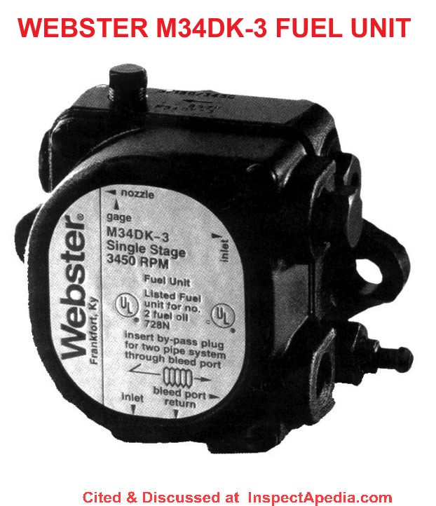
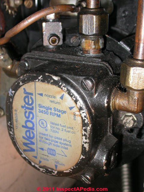
 Two common brands of widely used fuel units for oil burners are Danfoss Sunstrand or Suntec (photo at page top) and Webster (images at left and above-left). At left is a Webster single-stage 3450-rpm fuel unit.
Both companies make a range of excellent products that in our experience have proven durable and simple to install and maintain.
[Click to enlarge any image]
The single-stage Sunstrand J-pump and the two-stage Sunstrand H-pump were among the most widely used fuel units we encountered when servicing heating equipment in the Northeastern U.S. Webster's M-series fuel units are also widely used as OEM equipment on a variety of oil burners found on residential heating boilers, furnaces, and water heaters.
Manuals for oil burner fuel units are found
Single stage & two stage fuel unit operating capabilities
Quoting from Webster's description of their current product line we can read the typical capabilities of modern heating oil fuel pumping units:
Single and two stage models with 1725 and 3450 rpm operation feature compact design and field-proven reliability.
These units, rated @ 3 to 25 gph (11 to 57 1/hr.) @ 100 psi (6.9 bar), can be used on one or two pipe installations. ... Operating pressure [on heating oil fuel units] is factory [typically] set at 100 psi.
Commercial capacity oil burner fuel pumps
Larger, commercial-application fuel pumps are of course also available, such as Webster's R-series fuel pumps that can deliver up to 75 gph and even V-pumps capable of firing equipment at up to 260 gph (gallons per hour) - far larger than any home application.
Oil Burner Fuel Unit Rotation Direction - CW vs CCW or left hand vs right hand
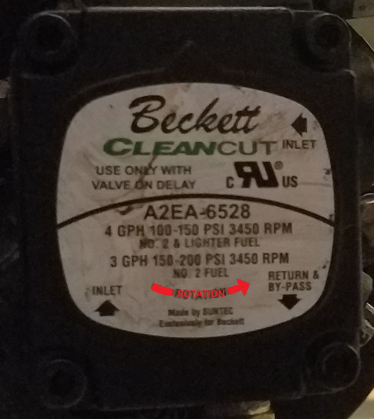
Fuel units for oil burners are sold in "left-hand" and "right-hand" rotation to meet different electrical motor and oil burner configurations.
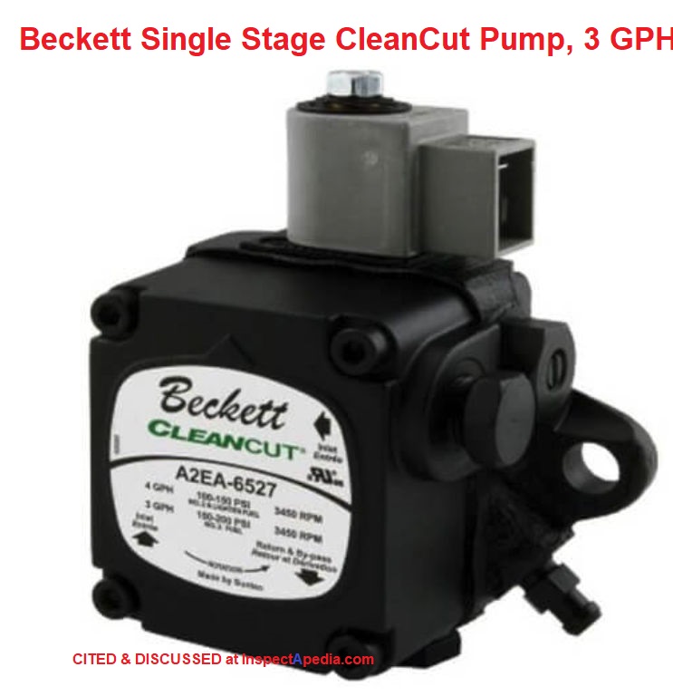
The direction of rotation of a fuel unit is marked on the fuel unit label (shows as our red arrow on this Beckett Clean cut oil burner fuel unit) or possibly on some older Sunstrand pumps as a casting into the fuel unit body.
The direction of rotation is interpreted by viewing the fuel unit from the shaft end.
Thus the fuel unit shown above is actually rotating in a clockwise direction (as it would be viewed from the other side, from the shaft end).
Installation & Adjustment Procedures for an Oil Burner Fuel Unit
What are the Connections or Ports on a Heating Oil Fuel Unit?
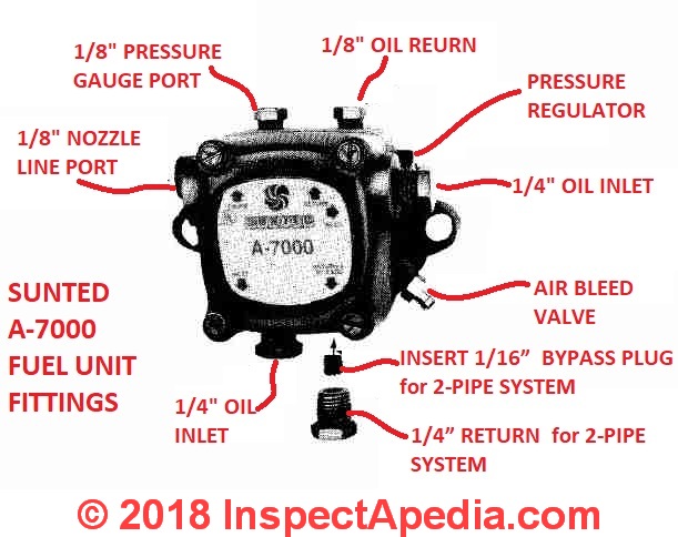
As we describe and illustrate (Suntec ports and components are illustrated at left, courtesy Suntec - click to enlarge any image) in this article a typical fuel unit or "heating oil pump" will have these connections and controls:
- An inlet port - feeds oil from the oil tank into the pump or fuel unit
- Oil delivery pressure to the burner (adjustment screw)
- Oil return or outlet port or external bypass port - can be used in a two-pipe hookup to return oil to the oil tank
- Pressure gauge port
- Nozzle line port - high pressure oil delivered to the oil burner nozzle
- Heating oil inlet port
- An internal bypass port or cover - possibly accessed through the bypass port, an internal plug can be installed or removed
- Air bleeder valve
These features will be reversed if the fuel unit rotation direction is reversed, and they may be in different positions on different models and brands of oil burner fuel units. Not directly accessible from outside the fuel unit are additional important parts found on most heating oil pumps (or if you want to sound like a pro, call it a "fuel unit").
- An internal check valve (discussed below)
- An internal filter screen (maintenance or service item on most units, discussed below)
Single-line Heating Oil System Fuel Unit Oil Piping Connections, Hookups
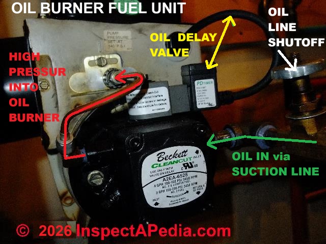 Where an indoor oil storage tank is installed on or close to the same level as the oil burner, it is common for a single heating oil line to bring oil from the oil storage tank to the fuel unit. In a single-line installation, an internal check valve found in the fuel unit prevents oil backflow into the oil lines when the fuel unit stops spinning.
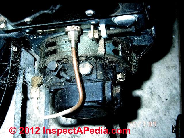
In our fuel unit photo (left) the green arrow marks the incoming oil from the oil tank and filter (under vacuum when the pump is running).
The red arrow indicates the high pressure oil being delivered from the fuel unit into the oil burner nozzle line.
This oil burner pump unit includes an oil delay valve , an electric solenoid switch connected through the burner tube over to the oil burner motor run circuit by an electrical wire. (yellow arrow).
The typical fuel unit used on modern oil burners does not have a high lift capacity - perhaps 6 feet would be a safe lift level for a one-line oil pipe installation.
Watch out: we have found single-line fuel unit hookups where a low or even a buried oil tank was installed. Such systems may "work" successfully for many years even though they violate good practice. Or the single-line hookup may work only if the oil level in the oil storage tank is kept pretty high (reducing the total lift required).
But on occasion we visited a property where there was recurrent loss of heat - a problem that was traced to the oil burner losing prime in the oil line.
The "fix" was to convert the system to a two-line oil pipe hookup described below.
Oil Burner Fuel Pump Lift Capacities, Flow & Oil Line Diameters
While individual manufacturer's oil burner pump (fuel unit) lift capacities vary by brand and model, in general the following table will apply to typical residential oil burners.
Oil Burner Fuel Unit Lift Capacities |
||
| Pump Type | Inches of Vacuum | Feet of Lift |
| Single-Stage Pump | 5-10" | 5-10 ft. |
| Two-Stage Pump | 10-15" | 10-15 ft. |
| Oil Line Piping Effects on Suction Line Lift | ||
| One Foot of Lift | 1" | -1 ft. |
| Each 90° Elbow | 1" | -1 ft. |
| Each foot of 3/8" ID Oil Line | 1" | -1 ft. |
Notes to the table above
Effects of oil line length on lift capacity and also on fuel flow capacity (table below) are in essence friction losses in the oil piping.
The Beckett CleanCut fuel unit may be installed with gravity feed or lift. The maximum allowable lift for a single pipe installation is 8 ft.
Sources:
- Beckett, INTRODUCTION to the BECKETT CLEANCUT FUEL UNIT PART I [PDF] retrieved 2019/12/3 original source: https://www.beckettcorp.com/support/tech-bulletins/an-introduction-to-the-beckett-cleancut-fuel-unit-part-i/
- NORA, FUEL UNITS & OIL VALVES [PDF] NORA, National Oil Heat Research Alliance, 600 Cameron Street
Alexandria, VA 22314 USA Tel: 703.340.1660 retrieved 2019/12/3 original source: https://noraweb.org/wp-content/uploads/2016/10/NORA-Silver-Chapter-4.pdf
Website Excerpt:
NORA stands for The National Oilheat Research Alliance, it was authorized by Congress in 2000 to provide funding that would allow the oilheating industry to provide more efficient and more reliable heat and hot water to the American Consumers. As a government sanctioned “check-off” program, $0.002 is collected at the wholesale level on every gallon of heating oil sold. While it is mandatory, the benefits greatly outweigh the minimal cost.
The four key arms of NORA are Consumer Education, Professional Education, improving energy efficiency and safety, and Research Consumer Education allows NORA to reach out to the consumer and show that oilheat is a clean, safe, efficient and modern form of heating. This communication is essential to the industry’s survival.
Professional education, through the Technician Certification Program, provides continuing education, training and certification for oilheat service technicians. Lastly, NORA funding has helped a number of manufacturers to develop highly efficient heating equipment, such as condensing boilers and furnaces, variable speed furnaces, variable burners and number of other technologically advanced, highly efficient products. - OIL TANK PIPING & PIPING DEFECTS - home
- OIL LINE VACUUM & PRESSURE TESTS
Oil Burner Fuel Line Diameters & Lift or GPH Capacity Losses |
|
| GPH Capacity | Oil Line O.D. |
| Up to 30 GPH | 1/2" OD |
| Over 10" vacuum w/ Single Stage Pump 2-Line System | Increase to next OD Size |
| Over 15" vacuum w/ Two-StagePump Two Pipe System | Increase to next OD Size |
Notes to the table above
Additional pipe diameter or pump capacity may be needed to overcome the resistance (or vacuum) created by the fuel unit's external oil filter, by additional elbows, sharp bends, and check valves.
Source: Webster FUEL PUMP PRESSURE DATA [PDF] retrieved 2019/12/30 original source: http://www.websterfuelpumps.com/pdffiles/tubeloss.pdf
Two Line Fuel Unit "Heating Oil Pump" Unit Piping Hookups
 A two-line fuel unit hookup simply means that there are two oil pipes between the fuel unit and the oil tank. A two-line oil piping system is generally required when oil is being pulled from the top of an above ground oil storage tank and it's always required when oil is being pulled from a buried or underground oil storage tank.
One line is the delivery line - from oil tank into the fuel unit, and the second line is the "return line" through which excess oil pumped by the unit flows back to the oil tank.
A two line oil piping system, required for buried oil tanks or oil tanks located below the oil burner, increases the "lift" capacity of the fuel unit and also nearly eliminates oil piping priming problems.
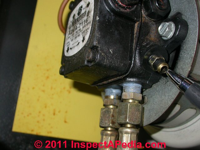
Our photo (left) shows a two-line oil piping hookup on a Suntec fuel unit - it's pretty easy to see since both the supply oil pipe and the return oil pipe connections are visible at the bottom of the fuel unit.
My pen is pointing to the air bleeder fitting on this fuel unit.
The oil inlet hookup is on the left and the oil "bypass" or "return" hookup is on the right. The label on the heating oil fuel unit face also will identify the various ports on the device.
A third oil pipe, the high pressure line from the pump outlet to the oil burner nozzle assembly is not clear in this photo, though you can make out a small brass tubing loop at the upper left in our photo - a part of the high pressure oil line.
Where a buried oil storage tank is installed or where the oil storage is significantly lower than the oil burner a two-line oil piping hookup is used to give added lift capacity to the fuel unit.
Watch out: check the fuel unit installation instructions and be sure that the internal check valve is set to the proper condition on the fuel unit when changing from a one-line to a two-line oil piping hookup, or vice versa.
Watch out: about installing a fusible link in the wrong place, causing an oil line blowout and fire contributor - as we discuss
at FIRE SAFETY CONTROLS
and
at OIL SUPPLY LINE SAFETY VALVES, OSVs, when a two-line oil piping system is in use, the fusible link oil safety valve should be installed only on the oil supply line. A check valve without a fusible link is typically installed on the oil return line.
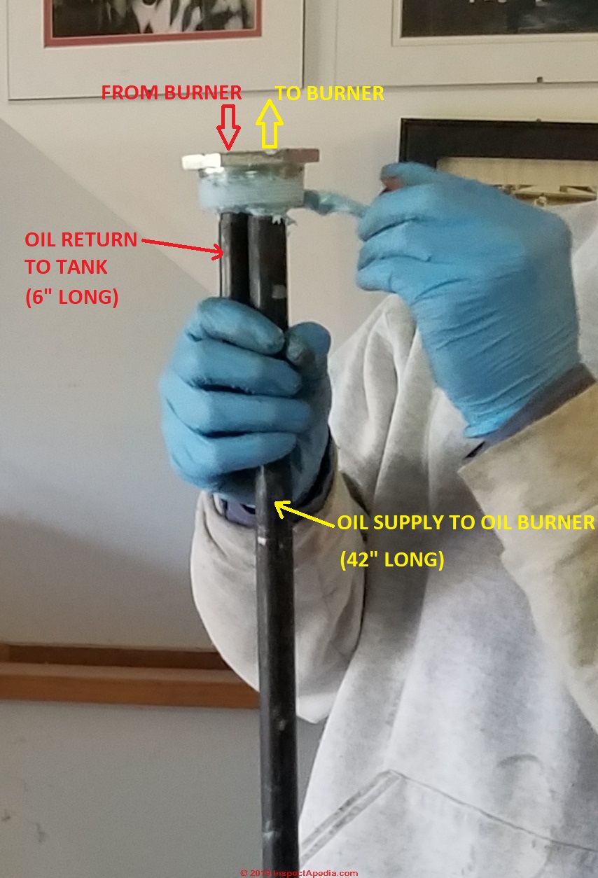
Above: preparing a two-line oil piping connection to be inserted into the oil tank.
On a typical 275 gallon 44-inch tall oil storage tank, the longer vertical pipe in our photo is a 42-inch long oil pick-up line that will deliver oil to the fuel unit at the oil burner, and a 6-inch long return line that delivers returning oil to the storage tank from the fuel unit.
The 42-inch long oil pick-up pipe thus stops about 2-inches from the bottom of the oil tank in order to avoid picking up water or sludge that may be present in the oil tank bottom.
Below: once the oil pick-up and return assembly has been installed in the oil tank top tapping the oil line supply and return lines are attached, as shown below. Here we are using 3/8" ID flexible L-copper oil piping encased in a polyethytlene protective sheath.
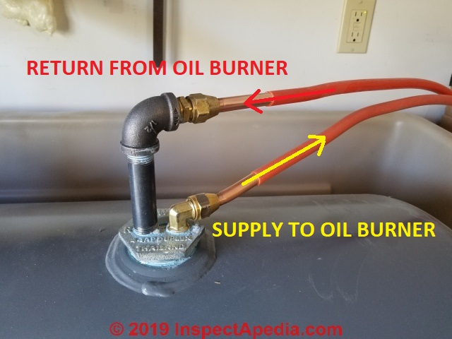
By attaching the oil supply line (to the burner) to the lower tank top connection the installer slightly-reduces the oil pump or fuel unit lift-height required, making life easier for the oil pump.
The oil return on the two line oil pipe system is fed to the taller of the two attachments shown in our photo above, simply to give working space to make the necessary oil line connections.
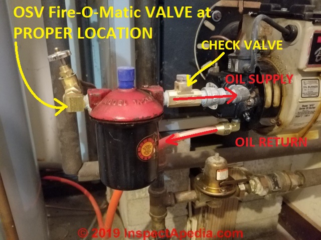
Above we show the two oil lines at the oil burner; the upper line supplies oil to the oil burner fuel unit, passing first through an oil safety valve or OSV, then through the oil filter, then through a check valve and into the oil burner's fuel unit or oil pump.
The lower oil line is the 2-line oil pipe system return line from the fuel unit to the oil storage tank.
See details at OIL SUPPLY LINE SAFETY VALVES, OSVs
Internal Fuel Unit Bypass Control - does the bypass plug go "in" or should it be "removed" ?
 Watch out: standard factory-set-up usually delivers a fuel unit with an "internal bypass" in the fuel unit "open". That's the set-up for a one-pipe oil piping hook-up.
When installing a two-pipe oil piping hookup to a fuel unit, an allen screw or plug is inserted into the fuel unit to close the internal bypass. The access to the internal bypass will be found beneath a service plug and will usually also be marked on a label on the fuel unit body.
A single-pipe heating oil system requires that the bypass plug is removed. Leaving the plug in the fuel unit will result in a blown seal, and oil leak, and loss of heat.
A two-pipe heating oil system requires that the internal bypass plug is inserted - in place. But kinked oil piping or piping blocked by sludge in the return line can still result in a blown seal in the fuel unit, an oil leak, and loss of heat. [8]
If a novice heating tech is having trouble remembering what to do with a bypass plug or port, just remember that we want only one excess pumped-oil return path - it's either inside the pump itself (an internal bypass is open on a one pipe oil piping system) or it's outside the pump and sends excess oil back to the oil tank (the internal bypass is then shut).
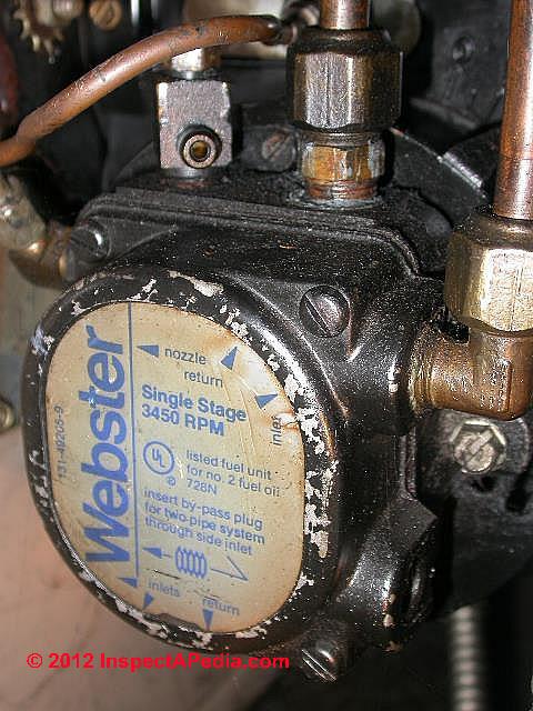
Our photo (above left) shows a modern single-stage 3450 rpm Webster fuel unit. If you are replacing the fuel unit on an oil burner you will need to note and match the following specifications:
- The rotation speed of the unit (1725 or 3450 "high speed")
- The direction of rotation (some pumps may be convertible) as "left hand" or "right hand" rotation direction.
At the bottom of the label in our photo above you can see a reference to the internal bypass plug along with a warning note and an arrow pointing to the threaded "plug" that is either installed (internal bypass closed, two pipe installation) or removed (internal bypass open, one pipe installation).
Our fuel unit shown above, also a Webster unit, tells a story without having performed any tests.
It appears from the dirt and cobwebs that no one has touched this device - a clue about its service history.
Typical Pressure Settings on Heating Oil Fuel Units
 When Carol Schnierer and I (DF) serviced heating equipment back in the dark ages, typical fuel unit pressure factory setting was to 100 psi.
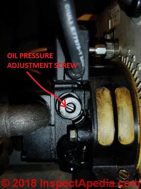
The pump output can be adjusted on most fuel units, typically within a range of about 100 psi up to 150 psi.
At oil burner school we learned to set the fuel unit pressure up to 110 or even 120, adjusting the nozzle size down to a smaller gph nozzle to keep the overall fuel delivery rate at the intended design point for the oil burner. That higher pressure gave better, finer oil spray delivery and more efficient oil burner operation.
Currently we see new oil fired heating equipment using 125 psi as a "standard" pressure setting.
Modern fuel units such as the Webster M34DK fuel unit is able to maintain its 3 gallon fire size throughout the 100 to 150 psi pressure range.
Our heating service tech Bob, from Bottini Oil, recently installed a replacement fuel unit on our lab's oil burner assembly.
In setting up the system, a 15 year old cast iron Peerless boiler with a Beckett oil burner, Bob set the oil pressure up to 140 psi, and the smoke was set first to "trace" and then (with a slight combustion air boost) down to "zero" - what he regards as current optimum settings for contemporary high speed oil burner units on newer heating equipment.
Watch out: check the labels or tags on your oil burner: the manufacturer will often specify the oil pressure at which the burner is designed to operate, as we illustrate just below.
Do not guess at the oil pressure setting. Unless you install an oil pressure gauge on the nozzle line side of the oil burner you will have no idea what the fuel unit's outlet pressure actually is.
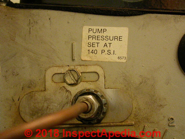
This oil burner fuel unit pressure data tag was fixed to the oil burner assembly just above the high pressure nozzle line inlet connector on a Beckett oil burner.
Also see OIL LINE VACUUM & PRESSURE TESTS
Bleed air out of oil piping and oil burner fuel units
Details are now found at OIL BURNER FUEL UNIT AIR BLEED PROCEDURE
Annual Fuel Unit Service & Repair Guide
Change-out of the Internal Filter Screen on Heating Oil Fuel Units
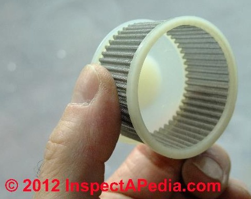 Oil burner fuel units typically use an internal filter/screen to help protect the pump internal parts and the oil burner nozzle.
While a proper heating system installation will include a canister-type oil filter on the oil piping ahead of the oil burner, for several reasons debris can escape the filter and enter the oil pump body.
This screen should be replaced as part of annual oil burner service. The screen comes with a new gasket that should also be used.
Watch out: if you fail to properly torque the four bolts holding the fuel unit cover over this screen assembly, air leaks in and oil leaks out at that location will prevent proper fuel unit operation.
Debris-clogging at the oil burner check valve
Watch out: when the fuel unit screen is never replaced, debris entering the oil pump can cause two common operating problems, both leading to improper and even unsafe oil burner operation:
Debris can clog the oil burner check valve (discussed just above) causing the valve to fail to stop oil delivery quickly when the oil burner stops running. The result can be a sloppy oil burner shut-down, oil burner nozzle clogging, and loss of heat or an oil burner puffback
Debris that prevents the internal check valve from closing may also allow oil from an oil storage tank to feed through the fuel unit by gravity, flooding the combustion chamber and risking a dangerous oil burner puffback, explosion or fire when the system re-starts.
During a service call on a very old oil burner in Poughkeepsie, NY in the 1980's, we found a low-speed oil burner that would keep right on going even after we turned off electrical power to the oil burner motor.
It was scary. The combination of heating oil feeding past the failed check valve and into the combustion chamber along with very hot combustion chamber liner components was enough to keep a "fire" going in the combustion chamber of the old boiler.
Vacuum Checks at the fuel unit
Annual service for the fuel unit also includes a vacuum check for proper pump operation and to check for leaks in the input line.
See OIL LINE VACUUM & PRESSURE TESTS for details.
Internal Check Valve on Heating Oil Fuel Pumps: leaks, repairs, oil delay valves
An internal check valve on the fuel unit is designed to rapidly stop the flow of oil out of the pump and to the oil burner nozzle when the electric motor stops spinning. If the check valve is not working, as the electric motor shaft slows below its full operating speed, oil may be otherwise delivered to the oil burner nozzle at low-pressure.
In turn, low pressure oil delivery means incomplete combustion of the oil in the combustion chamber (it is not fully atomized or broken into a fine spray). Incomplete combustion of heating oil in turn clogs the oil burner nozzle, leading to sooting and even loss of heat or a dangerous oil burner puffback.
Because a failed or "sticking" oil burner pump check valve causes serious operating problems and because this internal part is not easily repaired in the field there are two common repair approaches:
- Replace the entire oil burner fuel pump or fuel unit
- Install an oil delay valve -
see OIL LINE QUICK STOP VALVES for details.
An oil delay valve is an electric solenoid installed on the high pressure oil line between the oil pump outlet fitting and the oil burner nozzle tube.
The oil delay valve can help assure clean oil burner start-ups and shut-downs by making sure that the electric motor spinning the oil burner air intake blower as well as the oil pump are up to full operating speed before the solenoid opens to allow oil to flow to the oil burner nozzle.
This article series explains the installation & use of
- FUSIBLE LINK OIL SAFETY VALVES
- OIL SUPPLY LINE VACUUM-ACTIVATED OSVs & PRVs ,
- OIL SUPPLY LINE CHECK VALVES On Heating Oil Lines, and
- TIGERLOOP™ or similar oil line de-aerator/prime-protection devices.
- Oil delay valves, also called quick-stop valves and also referred to as oil safety valves, are discussed separately
at OIL LINE QUICK STOP VALVES.
Drive shaft connections for oil burner fuel pumps on boilers, furnaces, water heaters
An electric motor mounted on one side of the oil burner drives a shaft that in turn spins both a combustion air blower (that draws combustion air into the oil burner tube) and the fuel unit. Both of those components are connected in line on the drive shaft of the electric motor using a somewhat flexible rubber or plastic and rubber coupling.
Older "slow speed" oil burners used a motor that rotates at 1725 rpm, a speed that in turn determines the speed of the blower assembly and the fuel unit as well.
Modern "high speed" oil burners use a motor that rotates at 3450 rpm, a bit noisier but because of the additional combustion air that these systems can provide, high speed burners typically operate at a higher efficiency than the older models.
Watch out: a stripped or failed or loose coupling can result in slow burner blower assembly or fuel unit rotation and improper oil burner operation, or in no oil burner operation at all. A bad coupling or bad coupling alignment (everything should be in a straight line, motor, blower shaft, fuel unit shaft) will also be a cause of noise at the oil burner or fuel unit.
Drive Shaft Bearing Leaks on Oil Burner Fuel Units
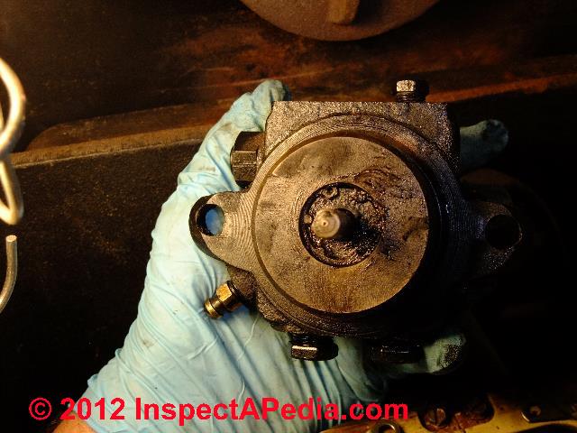
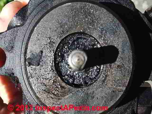
Damaged coupling joining the electric motor that drives the oil burner, the combustion air blower squirrel cage fan, and the shaft that turns the fuel pump unit itself.
In our photo, left, the heating service tech has removed the fuel unit (oil pump) from the oil burner to inspect for evidence of leaks around the oil burner's fuel unit drive shaft.
He did so after observing oil and debris and tar inside the burner tube assembly and on the oil burner's squirrel cage fan assembly. Because this fuel unit had a (small) leak around the fuel unit shaft, the entire unit was replaced.
In this CLOSEUP PHOTO of the fuel unit shaft leak you can see a tarry accumulation that convinced the tech (and us) of the leak problem.
What happens if we have even a small leak around the fuel unit drive shaft on an oil burner pump? Oil dripping into the oil burner tube soils the squirrel cage blower fan blades just enough that the blades accumulate and hold dust and debris.
The result is that while the fan may look ok, it is moving less air, leading to inadequate combustion air and a smoky sooty oil burner operation, eventually perhaps a puffback. Crud accumulating in the oil burner tube will eventually clog a small bleeder hole in the tube bottom, leading to still more oil and debris accumulation in this location.
The heating system articles provided at this website explain how to inspect and detect defects and hazards on heating systems, boilers, furnaces, and other equipment. Methods for saving on heating cost and on improving heating safety are included. Heating safety hazards such as carbon monoxide gas leaks, unsafe furnaces, furnace and boiler recalls are addressed.
Reader Question: leaks at Electro Oil Inter B9B burner in a Heatslave 15/19 boiler - Contacts for Danfoss Oil Burner Pumps
(Feb 21, 2014) Stewart Brown said:
Hi! We have an Electro Oil Inter B9B burner in a Heatslave 15/19 boiler.
Oil has started leaking, quite slowly, from the pressure adjustment screw on the front of the oil pump. Is there something I can tweak or tighten to cure this without turning a minor problem into a catastrophe?
Reply:
Hi Stewart.
What is the name brand on the oil pump? We ought to be able to look at its instruction manual to see what's sealable.
Typically there is a lock nut and a slotted screw that's turned to adjust the oil pressure, or on some units a recessed allen screw.
If yours is a Suntec fuel unit you can also contact Suntec’s
field service department at 800-367-7116.Keep me posted or send along a photo so I can ID and research your particular unit
(Feb 21, 2014) Stewart Brown said:
It has Danfoss on the front. The rest of the description is from the WEC Heatslave installation manual (Fig 24 on page 32). Sorry, can't fathom how to attach photo/manual extract.
(Feb 21, 2014) Stewart Brown said:
More sleuthing on the internet: It is very similar to a Danfoss BFP21. The front plate with the controls/adjusters is identical although the orientation of our main body (solenoid/bleed valve) is different.
Moderator Reply:
Stewart there are a number of Danfoss oil burner pump models and the company provides manuals online - though it sounds as if you've got one. From my scan of the documents I don't see an obvious cap or leak discussion.
If there is a faceted fitting at or around the pressure adjustment screw port you might try gently tightening that to be sure it's secure;
I would give Danfoss a call to ask about the leak you are observing: a concern is not just oil leaking out but the possibility of air leaking in - which can cause burner malfunction.
You don't say where you are located so I'm giving just contact information for North America; there is additional contact data for other countries
You'll see that for most of these fuel units there will be more than one way to hook up fuel lines, that may be the difference; also there are LH and RH rotation models that can be confusing to some. There ought to be a label on the unit giving model number, though on occasion the oil burner company or a service tech may have re-labeled.
If you want to use our CONTACT link to send me photos of the unit and a sharp closeup of where you see a leak I may be able to comment further.
(Feb 21, 2014) Stewart Brown said:
I have found the schematic! P1 on: heating.danfoss.com/PCMPDF/DKBDPD010E302.pdf but it doesn't answer the practical problem I have!
Moderator Reply:
give them a call and let me know what advice you receive; if you call a tech s/he will either just tighten something or will replace the unit. We don't know if there is a repairable seal.
(Feb 21, 2014) Stewart Brown said:
There is a slightly clearer document: oilburnerspares.com/products/images/pages/file/danfoss/Danfoss%20Oil%20Pump%20type%20BFP.pdf.
It is a deep seated screw with an allen key head.
Function: to adjust oil flow. The screw thread is adjustment rather than seal & it is starting to look as if the diaphragm in our unit has given up the ghost. I can't really complain about longevity but it is a nuisance nonetheless!
Reply:
Sounds as if a tech would at this point replace the fuel unit.
Be sure to get exactly the right one, including rotation direction; a service tech will know how to measure vacuum, adjust nozzle line pressure, and bleed air.
We give contact information for Beckett, Danfoss, Sunstrand, Suntec, and Webster oil pumps below.
Oil Burner Fuel Unit Suppliers, Manuals, Adjustment Guides
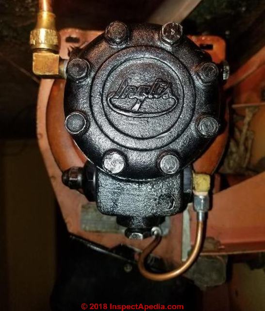 Shown here, an Inglis fuel unit, or oil burner pump, now branded as Sunstrand/Inglis fuel units, in essence the Sunstrand J-pump series.
Photo contributed by Inspectapedia.com reader Vladimir, rotated "upside down" to make the Inglis brand dlear. [Click to enlarge any image]
- OIL BURNER MANUALS provides links to manuals for oil burners, controls, fuel units, etc.
- [2] Beckett MODEL SR OIL BURNER INSTRUCTION MANUAL [PDF] R.W. Beckett Corporation, PO Box 1289, Elyria OH 44036 and R.W. Beckett Canada, Ltd., 430 Laird St., Guelph, Ontario, Canada N1G 3x7
- [3] Thanks to Bottini Fuel [website] service technician Bob for discussing the buzzing aquastat relay problem, 4/18/2012. Bottini Fuel is a residential and commercial heating oil distributor and oil heat service company in Wappingers Falls, NY and with offices in other New York locations. Bottini Fuel, 2785 W Main St, Wappingers Falls NY, 12590-1576 (845) 297-5580 more contact information for Bottini Fuel at http://www.bottinifuel.com/contact/
- [4] Beckett MODEL SF OIL BURNER INSTRUCTION MANUAL , op.cit.
- BECKETT CLEANCUT PUMP INSTRUCTIONS 5285-001 Service & Installation [PDF] (2020) www.beckettcorp.com,
USA: R.W. Beckett Corporation, 1-800-645-2876 -
Canada: R.W. Beckett Canada Ltd, 1-800-665-6972
Instructions for the Beckett fuel unit models CleanCut PF20322 CleanCut PF20323 CleanCut XL PF20422
Below: Beckett Single-Stage CleanCut pump Model No. A2EA-6527 showing the solenoid valve atop the fuel unit that assures a rapid and complete shut-off of oil flow when the pump stops.
- Danfoss, DANFOSS BURNER COMPONENTS SERVICE MANUAL [PDF] (2012) also see the company's website: burner.danfoss.com
- Danfoss, (older version of the above) DANFOSS OIL BURNER SERVICE MANUAL [PDF] (2010) U.K. version
- Danfoss, SERIES 90 PUMPS SERVICE MANUAL [PDF] (2020)
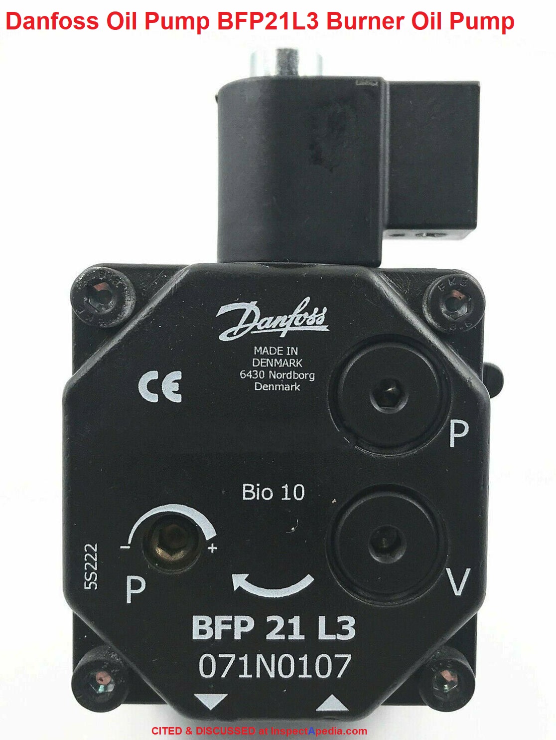
Below: Danfoss BFP 21 L3 Oil burner Pump model Bio 10
- Danfoss Hago Inc.
Customer Service 1120 Globe Ave.,
Mountainside, NJ 07092,
Phone: 908-232-8687
Toll-free: 800-710-HAGO (4246) Fax: 908-232-7246 E-mail: hago@danfoss.com Todd Vitali, Phone: 908-232-8687 X209, E-mail: tvitali@danfoss.com - Danfoss Inc. Heating Division Baltimore Office 11655 Crossroads Circle Baltimore, MD 21220 USA Website: https://www.danfoss.com Tel: 443-512-0266 Fax: 443-512-0270 E-mail: heatingsales@danfoss.com
- Danfoss Inc. Heating Division Toronto Office 6711 Mississauga Road, Suite 306 Mississauga, ON, L5N 2W3 Tel: 905-285-2050 Fax: 905-285-2055 E-mail: heatingsales@danfoss.com
- [5] Sunstrand Corporation - Sunstrand Fuel Units, 4949 Harrison Avenue
P.O. Box 7003
Rockford, Illinois 61125-7003
U.S.A.
Telephone: (815) 226-6000
Fax: (815) 226-5399
http://www.sundstrand.com
Note: Inglis fuel units or oil pumps are currently marketed under the brand Sunstrand/Inglis and are typically matched by Sunstrand J-Pumps.
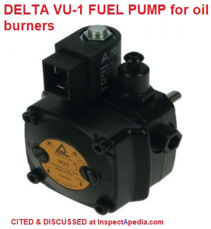
Below: a Delta VU fuel pump used in oil burner applications. On at least some Delta fuel units like the VU1 the rotational direction can be reversed without removing the pump cover. And like most fuel units there aer mounting ports for left-hand or right-hand nozzle port connections and the pump can be converted between 1-pipe and 2-pipe oil line installations.
Photo adapted from Anglo Nordic, a U.K. supplier of Delta fuel pumps. - Anglo Nordic Burner Products LTD 12/14 Island Farm Avenue West Molesey Surrey KT8 2UZ United Kingdom Website: https://www.anglo-nordic.com/
- Delta Pumps, DELTA Oil Burner FUEL UNIT Type CV, SV2 MANUAL [PDF] retrieved 2019/12/30 original source: http://www.patriot-supply.com/files/delta_cvsv_en.pdf Contact: Delta Pumps at www.deltapumps.com
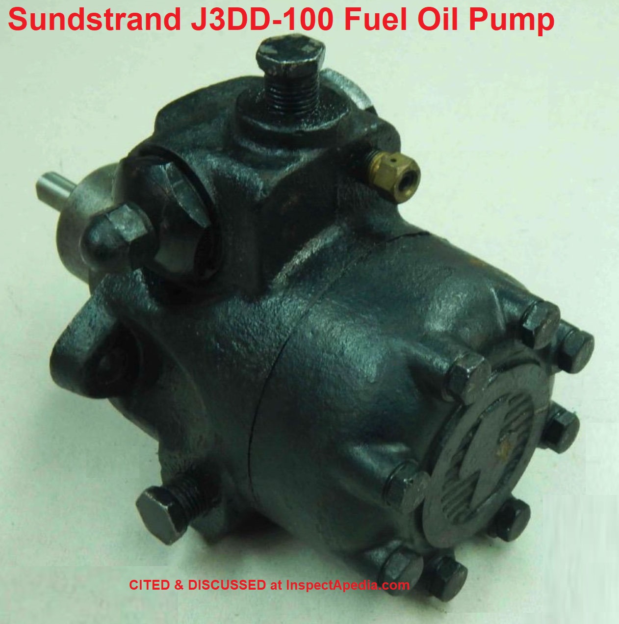
Below: an older Sunstrand oil burner fuel unit or "Sunstrand Suntec oil burner pump" - the SunTec Sundstrand J3DD-100 Fuel Oil Pump as for sale on eBay in 2021. Older Sunstrand pumps can be identified quickly by the raised "S" on the cast-iron pump cover. Often these older pumps were used on oil burners whose motors rotate at 1725 rpm - half the speed of modern "high-speed" oil burners spinning at 3450 rpm.
Watch out: when selecting a replacement fuel unit or oil burner pump be sure to match the pump's capacity, rotation direction, and operating speed to the original.
- [6] SUNSTRAND TRANSMISSION SERVICE MANUAL [PDF] May 1974, web search 08/19/2011, original source: http://www.cushmantrackster.com/pay-pdfs/sundstrand.pdf - Sunstrand Series 15 hydrostatic transmissions
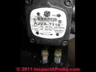
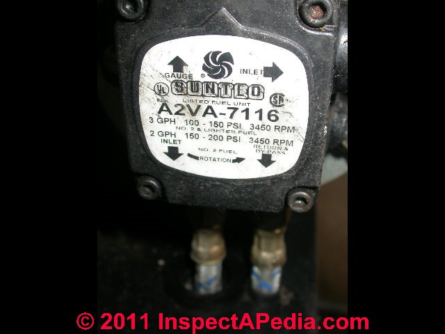
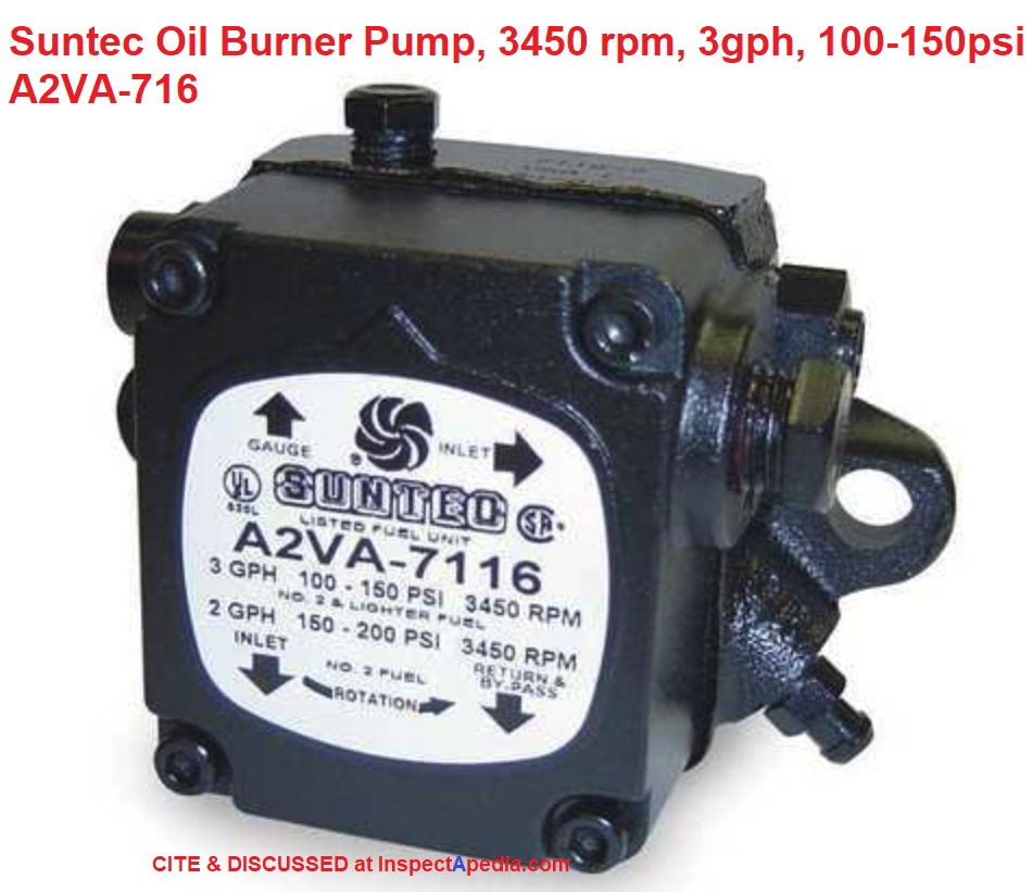
Below: Suntec Oil Burner Pump, 3450 rpm, 3gph, 100-150psi, model A2VA-7116 widely used on many oil burners. SunTec is a Sundstrand brand.
- [8] SUNTEC MODEL A-7400 Fuel Unit SOLENOID DUMPING PUMP [PDF]
Suntec Industries Inc., 60 Aberdeen Drive - PO Box 5000
Glasgow, KY 42142-5000 - USA
Tel : 270 651 7116 - Fax : 270 651 9276
e-Mail : info@suntecpumps.com and
Suntec Industries France, 1 Rue Lavoisier - B.P. 102 F-21603 LONGVIC Cedex - FRANCE Tel : +33 (0)3 80 70 60 70 - Fax : +33 (0)3 80 70 61 11 e-Mail : information@suntec.fr,
Also see SUNTEC SOLENOID OIL SAFETY VALVE BROCHURE [PDF] web search 4/19/12, original source: http://www.suntecpumps.com/Suntecus/PDFs/Form%202740%20 -%20Solenoid%20Dumping%20Pump.pdf - [9] SUNTEC MODEL PRV-38 OSV Oil Safety Valve Installation Information [PDF] Suntec Industries Inc., 60 Aberdeen Drive - PO Box 5000
Glasgow, KY 42142-5000 - USA
Tel : 270 651 7116 - Fax : 270 651 9276
e-Mail : info@suntecpumps.com and
Suntec Industries France, 1 Rue Lavoisier - B.P. 102 F-21603 LONGVIC Cedex - FRANCE Tel : +33 (0)3 80 70 60 70 - Fax : +33 (0)3 80 70 61 11 e-Mail : information@suntec.fr, You can download this file from Suntec's website.
Suntec's manuals for their fuel units are at www.suntecpumps.com/Technical%20Literature.htm
- Suntec, IDENTIFICATION MARKINGS on SUNTEC PUMPS [PDF] to identify the proper model and features of your oil Suntec fuel unit, for models AN, AE, AS, AL, ALE, AU, AR, AP and D pumps, and A 7000, A 3000, OL, B 8000 and B 4000 pumps, retrieved 2019/01/22, original source: http://www.suntec.fr/wp-content/uploads/2018/03/SB33EN_dec2018.pdf
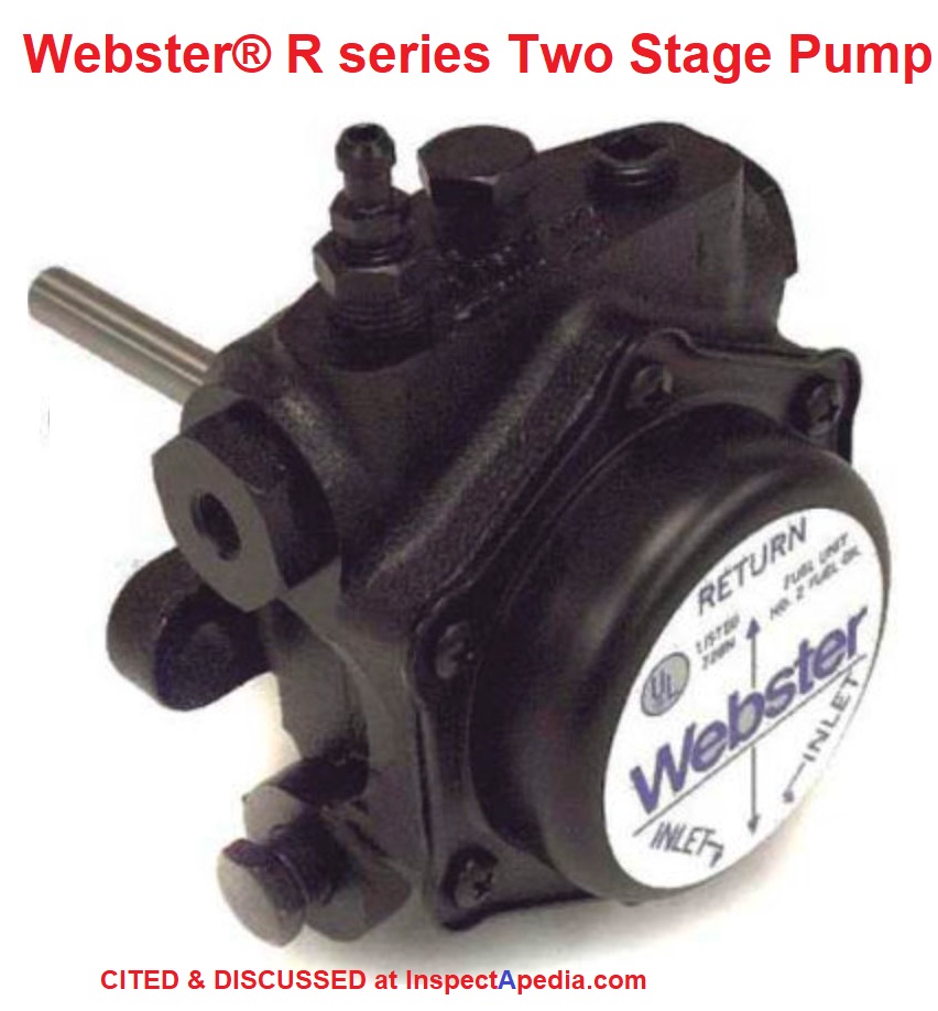
Illustration: Webster® R series Two Stage Pump 22R322D-5AA14, 3450 RPM, 34 GPH at 300 psi
- [7] Webster Fuel Pumps & Valves, Capitol City Tool, Inc., Tel: (800) 367-7116 Web: http://www.websterfuelpumps.com/ Email: czahalka@suntecpumps.com
See also Suntec - above.
Webster provides fuel pump IO & service manuals at the company's website: http://www.websterfuelpumps.com/pump_docs/pump_doc.htm - Webster, WEBSTER FUEL PUMPS & VALVES INSTALLATION & SERVICE MANUAL [PDF] Division of Capital City Tool, Inc.,
Excerpts:
This Webster ® Service Technician’s Handbook is supplied as a service to our customers, dealers and installers.
It represents our efforts to share with them our experiences of many years with our products in the field, and to also provide condensed catalog information to you on Webster products.
This booklet is not intended to be all-inclusive, or to be directly applicable to products manufactured by any other company.
The following list includes the terms which are most common to the oil heating industry. Single-stage fuel unit: unit with one set of gears for both suction and pressure. Two-stage fuel unit: unit with two sets of gears, one for suction and one for pressure.
One-pipe system: one line, an line, from tank to fuel unit.
Two-pipe system: two lines, one inlet and one return line, from tank to fuel unit.
Bypass plug: small hex socket head pipe plug used to close internal port and convert unit from one pipe to two pipe operation.
Bleed: to remove air from system. Lift: oil drawn from a level below pump expressed in feet of lift or inches of mercury.
Head of oil: column of oil over fuel unit expressed in psi or feet.
Inlet port: port which receives oil from tank.
Bypass port: port which discharges surplus oil back to tank in two-pipe system.
Return line port: same as by-pass port.
Valve differential: number of pounds per square inch the pump pressure must drop from operating pressure to close nozzle valve.
Delivery: gallons per hour pumped from the nozzle outlet assembly of the fuel unit.
Gear Set Capacity: Gear Set Capacity: Total amount of oil being displaced by the pumps gear set(s). - Webster, WEBSTER M-SERIES FUEL PUMP INSTALLATION MANUAL [PDF] LL7970 for Webster oil pump models: M34-3, 2M34-3 3 gph 1 gph — M34-6, 2M34-6 6 gph 3 gph — M34-15, 2M34-15 15 gph 13 gph — M17-6, 2M17-6 6 gph 3 gph — M17-15 15 gph 13 gph — M34DK-3 3 gph.
- Webster, WEBSTER R-SERIES FUEL PUMP INSTALLATION MANUAL [PDF]
- Webster, WEBSTER SPM-SERIES FUEL PUMP INSTALLATION & OPERATION MANUAL [PDF] (2021) retrieved 2021/11/08, original source: http://www.websterfuelpumps.com/pdffiles/spm_pump.pdf
- Webster, WEBSTER V-SERIES PUMP INSTALLATION & SERVICE MANUAL [PDF] for single & two stage high-capacity fuel pumps (1998)
Using Biodiesel B6-B20 vs. B-100 in Home Heating System Oil Burners
See BIODIESEL HEATING FUELS for details about using biodiesel or bioheat fuels in oil-fired heating equipment: oil burners used to heat boilers, furnaces, water heaters, etc.
Reader Comments, Questions & Answers About The Article Above
Below you will find questions and answers previously posted on this page at its page bottom reader comment box.
Reader Q&A - also see RECOMMENDED ARTICLES & FAQs
Question: how to connect a Yellow Jacket heating oil pressure gauge to my Becket Cleancut oil pump
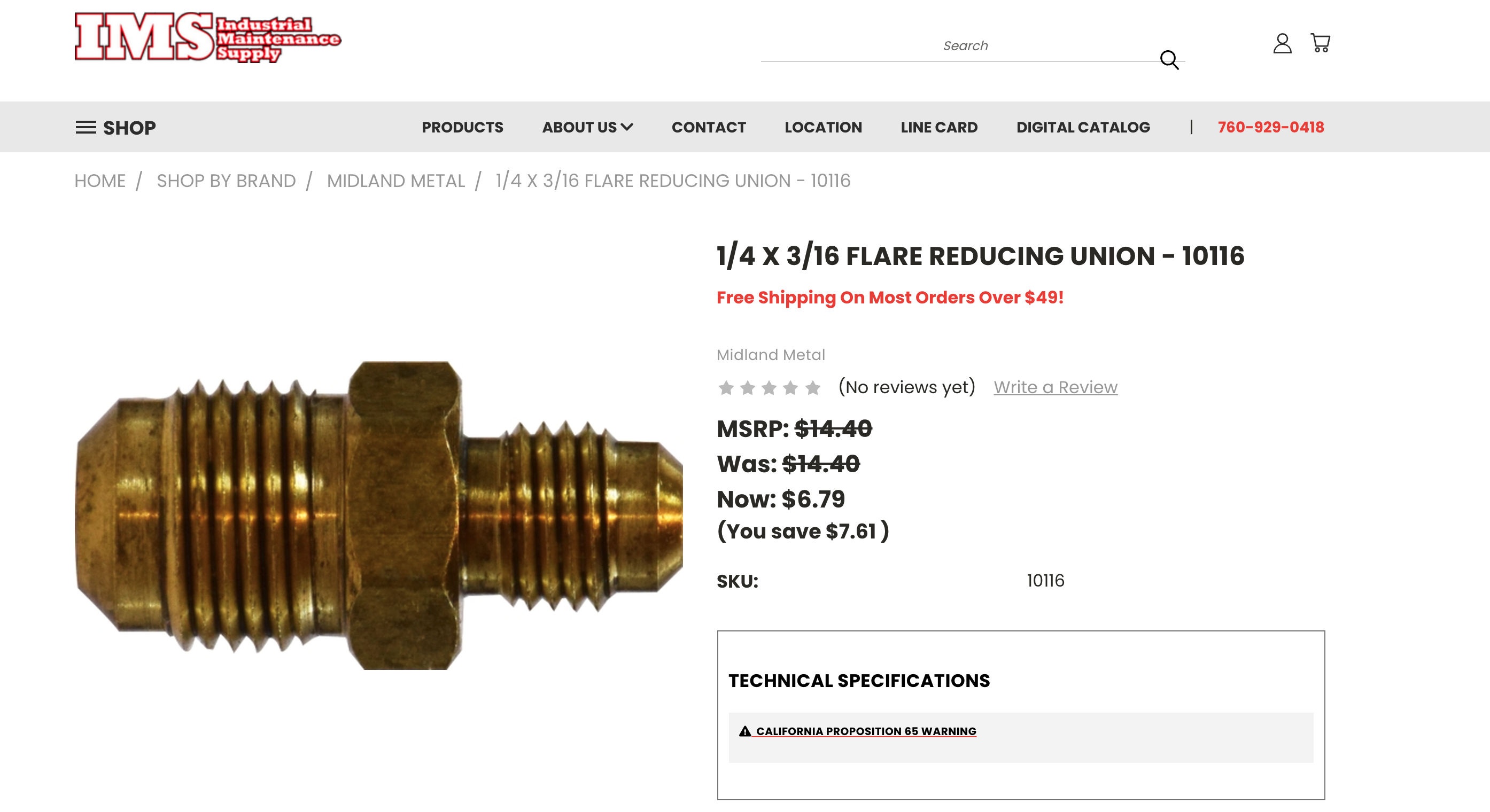
I'm trying to connect a Yellow Jacket heating oil pressure gauge to my Becket Cleancut oil pump. The gauge has a 1/4" hose with a female flare fitting and the pump has a male flare fitting (this is where the 3/16" nozzle line connects).
None of the supplied adapters work. If I could, I'd connect the gauge hose to the actual nozzle line which has a female flare at both ends, so either way, I'd be able to measure the pressure.
I CANNOT figure out how to make the connection from the 1/4" gauge hose to the 3/16" fitting on the pump. All suggestions are welcome; I'm frustrated.
Thank you.
Richard Garcia - 2021/09/09 [approx]
This Q&A were posted originally at HEATING SYSTEMS
Moderator reply: fitting an oil burner pressure test kit & gauge to a Beckett CleanCut fuel unit
I'm pretty nervous about this plan.
On the fuel unit output side (where I think you're planning to install a pressure gauge) the pressures can be well over 100 psi - up to 140 psi or more - so we want a dead reliable set of tubing and fittings between the fuel unit outlet and the nozzle line inside the burner head.
Watch out: A "hose" = sounds like rubber or plastic that can blow - leading to a catastrophe: an oil spill, oil spray all over the place, and a building fire. Be sure that any oil pressure testing setup uses hoses or tubing specifically rated for the application - as pressures at the outlet side an oil burner fuel unit can be well over 100 psi.
Where we see gauges installed on the high side of an oil system (and often even on the vacuum side) the best installation is using a tee through a shutoff valve, so that the metal tubing to the gauge is normally off - the valve is shut.
That worry expressed, I've sometimes had good luck with the larger suppliers like Grainger or IMS, companies that can provide flare fitting adapters between various tubing sizes. What you want to ask for is
at 1/4 X 3/16 FLARE REDUCING UNION like the one shown above, available at https://imsbolt.com/ and other plumbing and heating suppliers.
That plus a Tee, additional fittings, and a bracket to support your valve and gauge might work.
Reader follow-up:
Thank you. I didn't explain myself very well. The connection I described is between a simple, temporary hand-held pressure gauge with 8 inch rubber tube and the fitting on my Beckett oil pump. The measurement is to check the pressure setting (should be 100 psi) for a new oil pump.
The pumps are shipped set to 100 psi, but I just want to make sure it's set-up correctly. I need to attach the gauge hose to the 3/16" flare on the pump.
So I need a 1/4" male flare into the hose and the opposite of the union has to connect to the 3/16" male flare on the pump.
Yellow Jacket sells one for $35!!! that is for freon systems.
Thank you very much.
Richard
Moderator reply: example of oil burner pressure gauge set & parts
OK, sorry to be obtuse.
Yeah when I actually worked for a living I'd attache my gauge to the fuel unit outlet side to check the pressure.
You can buy a whole gauge set for less than the cost of that flare reducing union I cited above.
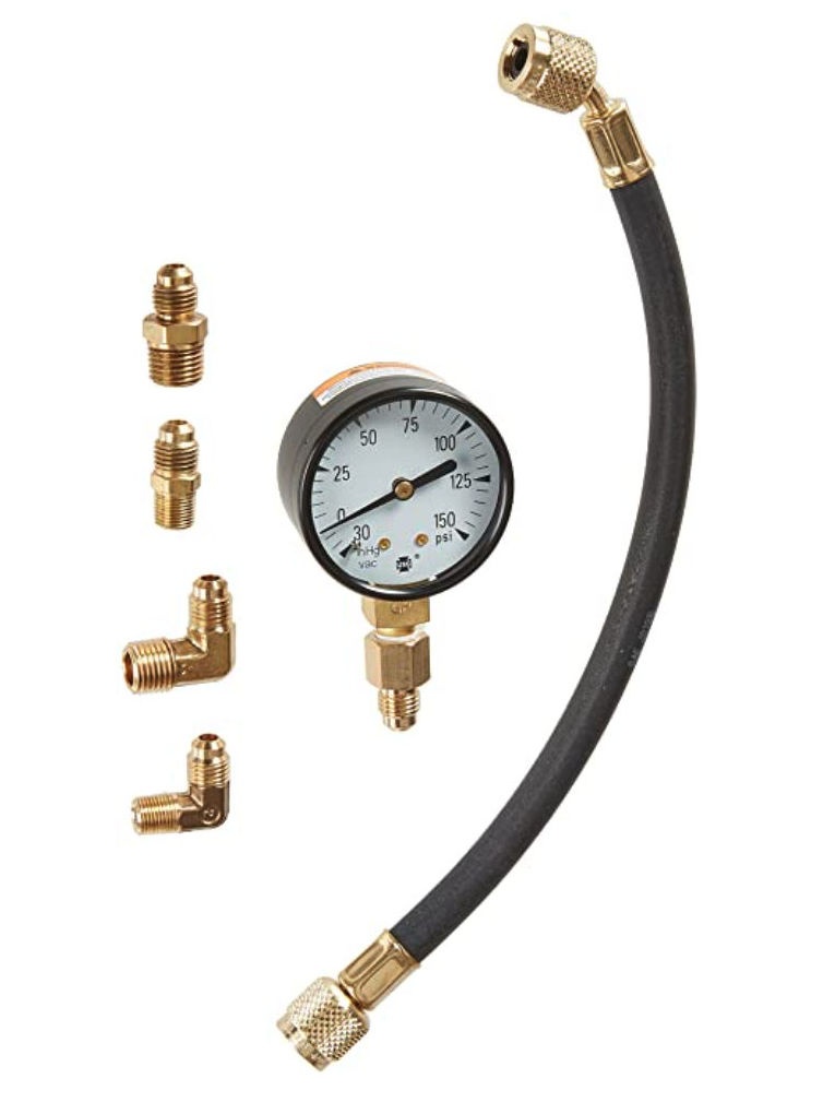
Your Yellow Jacket oil burner fuel unit pressure gauge test kit should have come with all the fittings you need to connect to the fuel unit. Exapels are in this screen shot from Amazon. That connects right to the outlet port on the fuel unit.
Watch out: without training and the full set of tools, even a handy homeowner can't properly tune and set-up an oil burner safely. Other measurements are needed such as CO2 or O2, smoke, and temperature.
Reader follow-up:
Thanks again Daniel. This is the exact kit I have, but none of the four adapters pictured connect to the 3/16" flare fitting on the oil pump. That's my problem. Westwood sells what I need but it's over $100 and I didn't know about it when I ordered the Yellow Jacket last year.
RG
Moderator reply:
RG
Usually you can unscrew the existing fitting on the fuel unit and screw in an NPT to flare that will connect to your hose.
Reader follow-up:
Thanks again. I tried that but the adapters I have to make this connection between the gauge hose and the oil pump are not the same. That confused me. I assumed it would be a standard NPT opening. I checked with a thread gauge. It doesn't seem right. I'll try again.
BTW, you've been very helpful and generous with your time. Thanks.
Richard
Moderator reply:
What are the brand and model oil burner? Usually we're going to find NPT.
Reader follow-up:
Beckett AFG (about 20 years old)
Moderator reply:
I think we are definitely doing something wrong here. That's exactly a very common oil burner and you should be able to do what you need let's make sure that your trying to make the connection at the right place. Do you have the service manual for your burner?
Reader follow-up:
Yes, of course.
I just re-measured the threads on oil pump nozzle port (flare adapter that the nozzle line attaches to). It is 24 treads/inch. My other adapters/unions of comparable size are all 18 threads/inch.
Moderator reply:
Check with your local plumbing supplier or give Grainger (1 800-GRAINGER) or Titan Fittings (866-533-4302 sales@titanfittings.com) a call to get an adapter that can convert 24 to 18 threads/inch in your diameter (1/4"?)
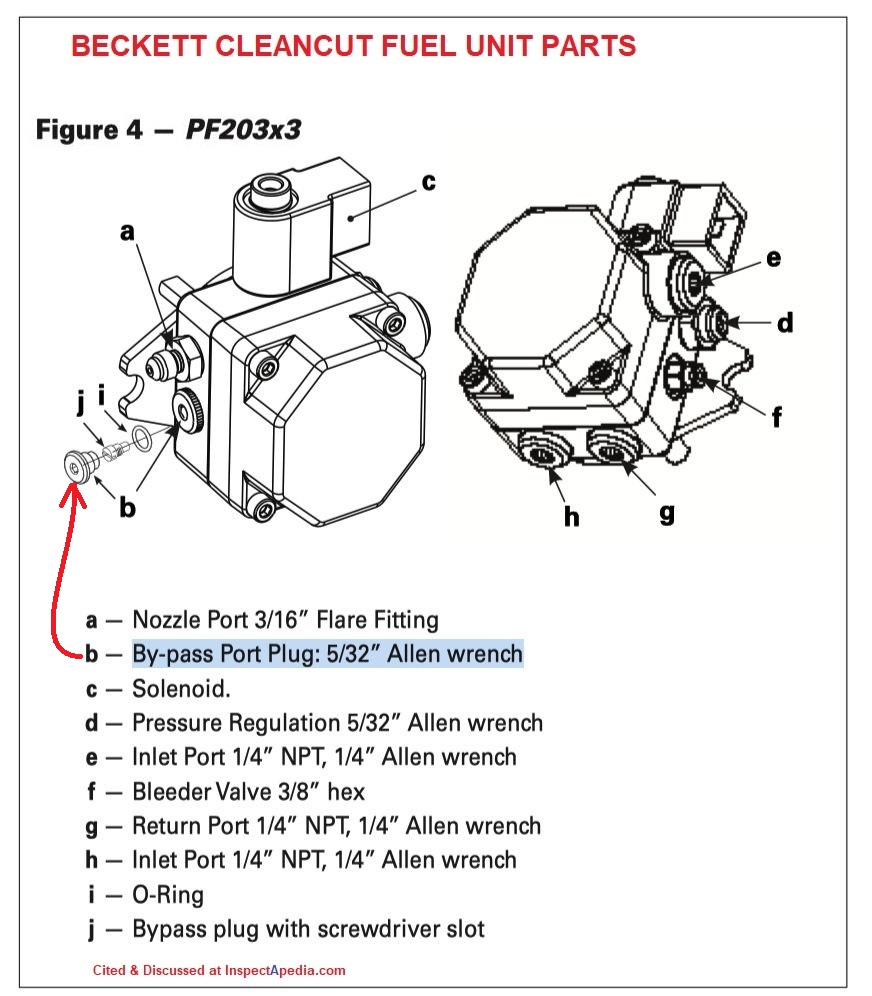
Reader follow-up: identify the bypass port plug on a Beckett Cleancut fuel unit oil pump
 Thanks Daniel.
One new question:
On the lower left side (as you face the Cleancut pump) there is a plug that is NOT identified in any diagrams.
What is it for? I'm not talking about the inlet plug for a two-pipe system. It is to the left of that at a 45 degree angle below the nozzle port. Thanks again.
Is it the bypass port plug?
Moderator reply:
Yes, Richard that's the bypass port plug - you'll see it identified on some Beckett Cleancut Oil Pump instructions such as this excerpt from the
BECKETT CLEANCUT PUMP INSTRUCTIONS 5285-001 Service & Installation [PDF] (2020) www.beckettcorp.com, USA: R.W. Beckett Corporation, 1-800-645-2876 - Canada: R.W. Beckett Canada Ltd, 1-800-665-6972
Instructions for the Beckett fuel unit models CleanCut PF20322 CleanCut PF20323 CleanCut XL PF20422Pleases see details about oil burner fuel units (oil pumps) at
where we will move this discussion
Question: my oil pump is using too much fuel
2021/07/31
My oil pump is too much diesel take to boiler so please tell me how to I will control to pump or just men diesel
- Anonymous by private email
Moderator reply:
This is more than fits in an email reply but if you go to our website inspectapedia.com and use the "on Page" InspectApedia search box to search for OIL BURNER FUEL UNIT and you will see a series of articles on diagnosing and repairing those pumps. I think however you may be barking up the wrong tree if you'll pardon the stupid pun.
What I mean is that the fuel unit output is controlled by of the pressure setting that you can adjust on the fuel unit but more importantly but more importantly by the size of the oil burner nozzle.
I found the pages you want,
start at
OIL BURNER FUEL UNIT - home also see
FUEL UNIT INSTALLATION & ADJUSTMENT PROCEDURES
Also see
And be sure to check the nozzle size range (in gph or lph) specified by the manufacturer of your heating boiler. That data is often also included on a sticker right on the oil burner.
On 2019-04-09 by Thomas Bruno - How do you adjust the rotation speed of an oil burner pump?
How do you adjust the rotation speed of an oil burner pump? Thank you
On 2019-04-09 by (mod) - The rotation speed of a oil burner fuel unit or oil pump is not adjustable.
Thomas
The rotation speed of a oil burner fuel unit or oil pump is not adjustable. The speed will be determined by the speed of the electric motor that drives the oil burner. That will normally be 1725 or 3450 RPM.
You can however adjust the fuel units output pressure. That adjustment is described in this article series.
On 2019-01-22 by Vladimir - where to find parts for an Inglis oil pump
Hey guys is anybody knows where I can find parts for Inglis oil pump or where I can buy it, thanks
IMAGE LOST by older version of Comments code - now fixed. Please re-post the image if you can. Sorry. Mod.
On 2019-01-22 by (mod) - Inglis fuel unit
Vladimir,
The Inglis fuel unit or oil pump brand is now part of the Sunstrand product line marketed as Sunstrand/Inglis.
Your fuel unit looks like the old Sunstrand J-pump so probably it can accept those parts - depending on just what you need, like a strainer or gasket.
If your pump is so old that no parts are available you can also replace the entire pump with a more modern Sunstrand J pump.
You will need to know the rotation direction of your unit, and you *might* need to replace the drive coupling between the oil burner motor and blower fan int he burner, and the pump itself.
If you're in the U.S. contact: SUNTEC Industries Incorporated 60 Aberdeen Drive GLASGOW, KY 42141 USA Tél : +1 270 651 7116 Fax : +1 270 651 9276 info@suntecpumps.com
In Europe contact SUNTEC Industries France Zone industrielle Dijon Sud 1 Rue Lavoisier CS 60102 F-21603 LONGVIC Cedex Tél : +33 (0)3 80 70 60 70 Fax : +33 (0)3 80 70 61 11 information@suntec.fr
On 2019-01-18 by Eric - trouble finding leak at oil pump on oil burner
I have a leak and can't pinpoint where it is coming from it only leaks a slight stream of oil when the pump shuts off
On 2019-01-19 by (mod) -
The danger with this kind of leak on the fuel unit is that when it's running your sucking air into the system which can ultimately lead to an improper flame and a proper oil burner operation even ultimately a puff back.
Wipe everything off thoroughly and perhaps try a dusting of talcum powder
On 2018-12-22 by scott - ticking sound at oil burner
i have a beckett oil burner .when it starts up .burns good.it has a ticking,hesing sound.for a few sec.it sounds like a dry injector
On 2018-12-22 by (mod) -
Scott
That's not a symptom I know how to diagnose without looking more carefully at the oil burner as it's operating: are we sure that the noise is from the burner and not a motor or motor coupling or from the burner's blower fan?
...
Continue reading at OIL BURNER FUEL UNIT DIAGNOSTIC FAQs or select a topic from the closely-related articles below, or see the complete ARTICLE INDEX.
Or see OIL BURNER FUEL UNIT DIAGNOSTIC FAQs - questions & answers posted originally on this page
Or see these
Recommended Articles
- FUEL UNIT BRANDS & PROPERTIES
- FUEL UNIT INSTALLATION & ADJUSTMENT PROCEDURES
- HEAT WON'T TURN ON
- OIL BURNER FUEL UNIT - home
- OIL BURNER FUEL UNIT AIR BLEED PROCEDURE
- OIL BURNER FUEL UNIT ANNUAL MAINTENANCE, SERVICE & REPAIR PROCEDURES
- OIL BURNER INSPECTION & REPAIR home page for oil burner diagnosis and repair
- OIL BURNER MANUALS
- OIL BURNER WONT RUN - Diagnostic Steps - what to check in what order
- OIL TANK PIPING & PIPING DEFECTS - home
- OIL LINE VACUUM & PRESSURE TESTS
Suggested citation for this web page
OIL BURNER FUEL UNIT at InspectApedia.com - online encyclopedia of building & environmental inspection, testing, diagnosis, repair, & problem prevention advice.
Or see this
INDEX to RELATED ARTICLES: ARTICLE INDEX to HEATING OIL, OIL BURNERS, OIL FIRED HEATERS, OIL TANKS
Or use the SEARCH BOX found below to Ask a Question or Search InspectApedia
Ask a Question or Search InspectApedia
Try the search box just below, or if you prefer, post a question or comment in the Comments box below and we will respond promptly.
Search the InspectApedia website
Note: appearance of your Comment below may be delayed: if your comment contains an image, photograph, web link, or text that looks to the software as if it might be a web link, your posting will appear after it has been approved by a moderator. Apologies for the delay.
Only one image can be added per comment but you can post as many comments, and therefore images, as you like.
You will not receive a notification when a response to your question has been posted.
Please bookmark this page to make it easy for you to check back for our response.
Our Comment Box is provided by Countable Web Productions countable.ca
Citations & References
In addition to any citations in the article above, a full list is available on request.
- [1]AUDELS OIL BURNER GUIDE, INSTALLING, SERVICING, REPAIRING, [PDF online copy of this book] Frank D. Graham, Theo. Audel & Co., New York 1946, 1947, 1955 (out of print, copies occasionally available from antique book dealers and on EBay). Use THIS LINK to read a free online copy of this helpful classic textbook.
- Fuel Oil & Oil Heating Magazine, 3621 Hill Rd., Parsippany, NJ 07054, 973-331-9545
- Domestic and Commercial Oil Burners, Charles H. Burkhardt, McGraw Hill Book Company, New York 3rd Ed 1969.
- The ABC's of Retention Head Oil Burners, National Association of Oil Heat Service Managers, TM 115, National Old Timers' Association of the Energy Industry, PO Box 168, Mineola, NY 11501. (Excellent tips on spotting problems on oil-fired heating equipment. Booklet.)
- In addition to citations & references found in this article, see the research citations given at the end of the related articles found at our suggested
CONTINUE READING or RECOMMENDED ARTICLES.
- Carson, Dunlop & Associates Ltd., 120 Carlton Street Suite 407, Toronto ON M5A 4K2. Tel: (416) 964-9415 1-800-268-7070 Email: info@carsondunlop.com. Alan Carson is a past president of ASHI, the American Society of Home Inspectors.
Thanks to Alan Carson and Bob Dunlop, for permission for InspectAPedia to use text excerpts from The HOME REFERENCE BOOK - the Encyclopedia of Homes and to use illustrations from The ILLUSTRATED HOME .
Carson Dunlop Associates provides extensive home inspection education and report writing material. In gratitude we provide links to tsome Carson Dunlop Associates products and services.
 | HOME | ABOUT | ASK a QUESTION | CONTACT | CONTENT USE POLICY | DESCRIPTION | POLICIES | PRIVACY | |
| © 2024 - 1985 Publisher InspectApedia.com - Daniel Friedman | |||||||||