
InspectAPedia® FREE Encyclopedia of Building & Environmental Construction, Diagnosis, Maintenance & Repair |
Question? Just ask us! InspectAPedia
|
 Radiant Heat System Controls, Definitions, Terms

- POST a QUESTION or COMMENT about radiant heat system controls, definitions, terms, features
Radiant heating system key components, terms, definitions:
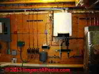
This article describes key controls, devices, & terms used with radiant heating systems. Our page top photo illustrates the heating boiler, circulators & mixing controls for a multi-zone radiant floor heating system installed during reconstruction of a home in Tivoli, NY.
InspectAPedia tolerates no conflicts of interest. We have no relationship with advertisers, products, or services discussed at this website.
Radiant Heating System Controls & Components
A radiant heating system used in buildings is comprised of heating elements embedded in building surfaces and a heat or energy source for those elements.
Electric radiant heat, popularized in the U.S. in the 1950's was installed in ceilings, using either flat electrical resistance heaters atop ceiling drywall or in special gypsum-board panels containing electric resistance heat wiring.
Similar systems were occasionally installed in poured concrete floors or under tile floors. But as most widely used in modern installations, radiant heat is installed in or beneath building floors using flexible tubing heated by water or a water-antifreeze mix that is in turn heated by a heating boiler.
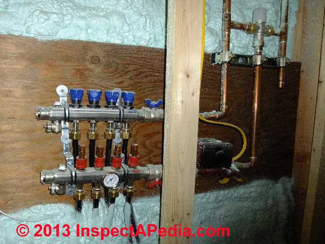
Our photo (above left) illustrates a four-circuit radiant heat installation and shows the supply and return manifolds at left and the mixing valve (gray control, upper right) in a Tivoli, NY home. Photo courtesy Ralph Arlyck, Timed Exposures.
To make a radiant heat floor system work well, in addition to normal controls found on any heating boiler (varying by boiler type: electric, LP or natural gas, oil fired, or possibly passive solar-heated) additional controls are usually found including these:
Article Contents
- RADIANT HEAT AIR ELIMINATORS / PURGERS
- RADIANT HEAT SYSTEM ANTIFREEZE
- RADIANT HEAT CIRCULATORDS, COUPLINGS, HEADERS, MANIFOLDS, ZONES
- RADIANT HEAT TEMPERATURE CONTROLS & SAFETY DEVICES
- RADIANT HEAT PRESSURE SETTINGS & GAUGES
- RADIANT HEAT RECOVERY RATE
- RADIANT HEAT CIRCUIT DESIGN, RESISTANCE & FLOW BALANCING
- RADIANT HEAT, CLOSED vs OPEN DESIGNS
- RADIANT HEAT TROUBLESHOOTING
...
Radiant Heat System Air Eliminators & Air Purgers
The air eliminator, typically part of an expansion tank and air purge kit, is a device used to vent air from the radiant heat tubing and piping system.
Without an automatic air purger on a hot water circulating heating system it is easy for water flow through the heating tubing to become blocked or air-bound.
The problem of air-bound heating systems is not unique to radiant heating, nor are its solutions, but as we explain below, in radiant floor heating applications it's easy to mistake an air-blockage in the system for other heating system problems.
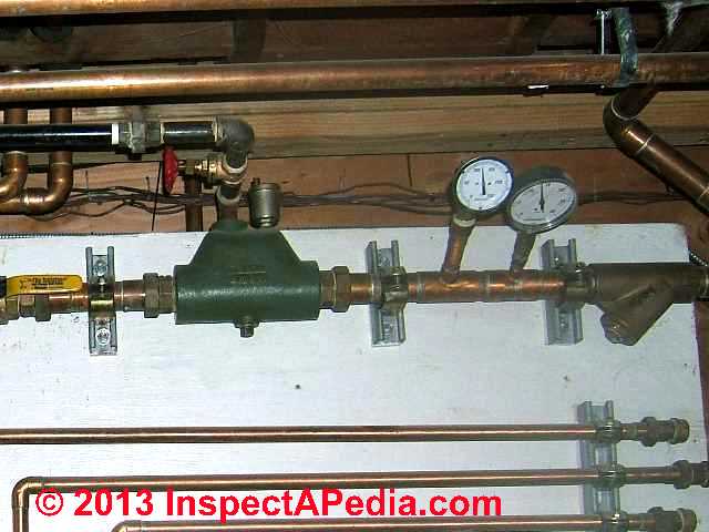
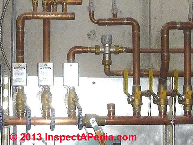
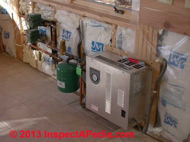
In our photo (above left) you can spot the air scoop/air purge device - the green device near photo center. on the top right of that air scoop you can see the brass-colored automatic air bleed valve that removes air collected in the air scoop or piping. At middle right of the photo you can see pressure and temperature gauges installed on the system.
Air bleeder valves are used with an expansion tank and air purge "kit" to manually remove air from the radiant heat tubing during installation.
While these components are found on other hydronic heating systems, often a factory-packaged radiant heating system installation will include a factory-designed plumbing package that includes all of the necessary fill and drain valves, expansion tank, air purge or air eliminator valve.
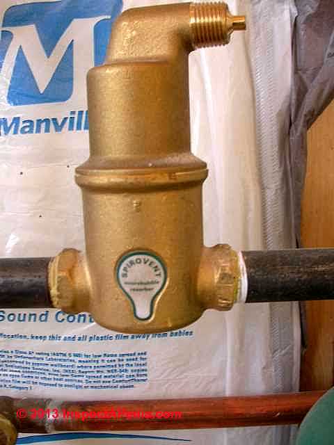
Our photo (left) shows a Spirovent air purger eliminator installed on a radiant heat floor system.
Watch out: while just about every hydronic-type radiant floor or ceiling heating system includes one or more air purging device, air in the tubing loops can reduce heat output or even prevent sections or entire heating zones from delivering heat. Air in the tubing may accumulate during a system shut-down, from leaks, or other defects.
See AIR BOUND RADIANT HEAT where we present a case history that documents diagnosing & repairing air-bound tubing loops in one zone of a three-zone radiant floor heating system.
Details about air bleeders and air purge devices
- AIR BLEEDER VALVES - types of air bleed valves, how they are used & installed
- AIR BOUND RADIANT HEAT - steps in diagnosing the problem of air blockage in one zone of a three-zone radiant floor heating system.
- AIR SCOOPS PURGERS SEPARATORS
- AIRBOUND HEAT SYSTEM REPAIR by WATER FEED VALVE
- EXPANSION TANKS
...
Radiant Heat System Antifreeze
Antifreeze is often included in the heating fluid mix for radiant heat installations. Installers may use either propylene glycol (non-toxic food-grade antifreeze, recommended where a tankless coil is used on a heating boiler and in some other cases), or ethylene glycol (automotive type and highly toxic antifreeze).
Details are at ANTIFREEZE for BOILERS.
...
Radiant Heat Circulator Pump(s)
A circulator pump is used to force heated water through the circuits of the radiant heat tubing. As with other hydronic heating systems, design may use a single circulator pump and multiple zone (or circuit) control valves or it may use multiple circulator pumps, one for each heating zone.
To provide zone heat control, each zone has its individual room thermostat that in turn operates the zone valve or circulator pump.
Details are at CIRCULATOR PUMPS & RELAYS.
Radiant Heat Adapters, Couplings, Headers & Zone Manifolds
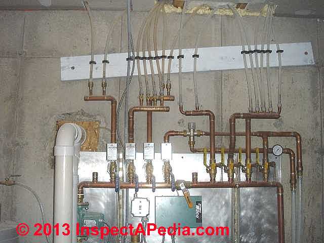
Our photo shows that there are four heating zones (we see four zone valves grouped on the left side of the manifold).
[Click any image to see an enlarged, detailed version.]
Special fittings are required to connect the radiant heat tubing (typically rubber or polyethylene or PEX) to copper piping that is required close to the heating boiler itself.
A header or manifold is a connecting device that feeds multiple radiant heat tubing loops from a single larger (usually copper) pipe that is in turn fed with hot water from the heating boiler. Each radiant heat tubing loop, routed through a particular heating zone or floor area, is referred to as a circuit.
A header may be used at either or both the supply and return ends of the radiant heating system piping. The advantage of using a header is the greater ease with which flow can be controlled and balanced among the various loops or zones in the radiant heat system.
A zone manifold for radiant heating systems (photo above left) combines the manifold itself, used to connect radiant heating circuits to the hot water supply with a pre-packaged assembly of circulator pumps, flow balancing valves, pressure testing gauge, and controls.
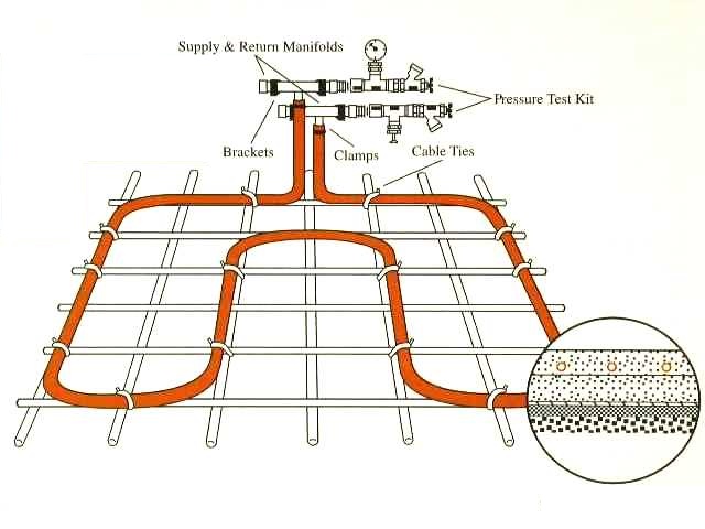
The sketch above shows a simple radiant heat floor installation diagram, courtesy Entran radiant heating, illustrating the pressure test kit connections to a radiant heating circuit.
But the system in our "real world" photograph (above left) is trickier than that. Look at that left-most zone and you'll see that its feed splits off into two sub-circuits or loops, both on the same zone;
The next-to-leftmost zone valve feeds four circuits, and so-on.
Most likely the installer did this either to distribute heating circuits within individual rooms or to try to balance circuit resistance. Each circuit has an individual balancing valve or control - all of which we observed were in the full "open" position.
Radiant heating control manifolds or "slab manifolds" provide from one to six individual circuit connection points.
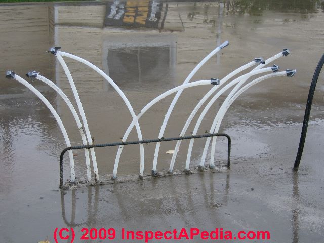
Manifolds for radiant heat circuit connections may be wall-mounted near the heating boiler or some installers actually place the manifold into the concrete slab itself, though it must be protected from actual contact with the concrete (to avoid corrosion issues and to assure access for inspection, maintenance, repair, adjustment).
We were a little worried when we saw this Two Harbors MN radiant heat tubing manifold arrangement as it was not obvious that a copper or brass manifold had not been buried in the concrete - but, then, the installation was incomplete.
Perhaps there were only a series of 90's in the concrete and the manifold was yet to be installed.
...
Radiant Heat Temperature Controls
Radiant Heat Installation & Operation & Temperature Guides are described and links to radiant heat temperature control devices and their installation and use are given here.
Radiant Heat Safety Devices, Controls: Temperature/Pressure Relief Valves, Mixing Valves, Temperature Controls
The water circulated through radiant heating system tubing is almost always required to be at a lower temperature than the normal output temperature of the heating boiler itself.
There are several reasons for the dichotomy: a heating boiler is generally more efficient when operated at higher temperatures; radiant heated floors would be uncomfortably hot and might also be damaged if water circulating through the radiant heat tubing is too high in temperature.
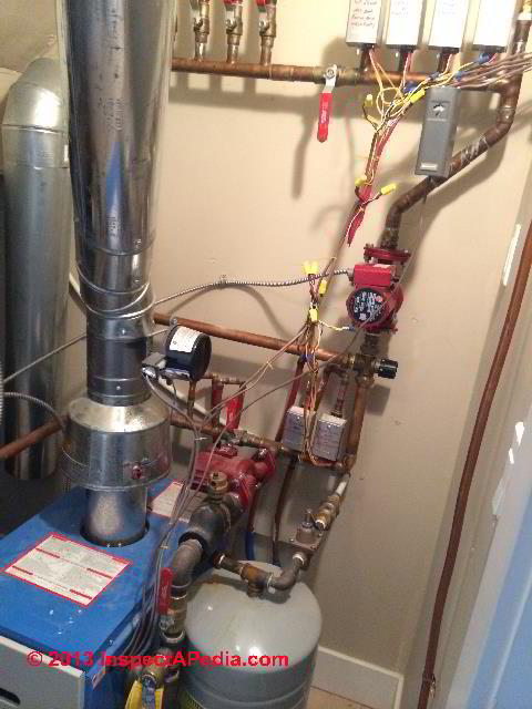
In our photo (left) we have circled the mixing valve installed between the cold return side and the hot feed size of the heating circuits.
Typically water leaving a conventional heating boiler is at 160-180 deg F.
The mixing valve mixes a small amount of very hot water from the heating boiler into the cold or returning water at the end of the heating loop, so that the temperature of water sent onwards through the radiant floor heating loop will be re-heated but not raised to an excessive temperature.
In addition, for some heating loops and heating conditions, the returning hot water (at the end of the heating loop) is still warm enough to re circulate, sending additional heat into the occupied space, without having to re-heat the water by turning on the boiler.
Below are instructions and other resources for popular radiant heat system temperature controls including thermostats, mixing valves and manifold controls .
- Azel Technologies, Inc., P.O. Box53138 Thornhill ON L3T 7R9 Canada Tel: 905-223-5567 Email: info@azeltec.com Web: azeltec.com- controls, temperature gauges & thermostats for radiant heating systems provides a wide range of radiant heat controls including examples and manuals provided at
RADIANT HEAT DESIGN & INSTALLATION MANUALS - PDF downloads in addition to those listed just below.

- TACO RMB-1 RADIANT HEAT TEMPERATURE CONTROLLER INSTRUCTIONS [PDF] (shown above)
- THERMAL IMAGING, THERMOGRAPHY an introduction to thermography and what to expect when using thermal scans to study radiant heat floor problems

- WATTS Series 1170, LF1170, L1170 and LFL1170 INSTRUCTIONS [PDF] (2010) (illustrated just above)

Below: Watts illustration (edited by IAP) showing how the LF1170 or LFL1170 is plumbed when used to control temperatures in a radiant heat system.

Watch out: Don't confuse radiant heat mixing valves and temperature controls when used as radiant heat system temperature controls and often the same devices when used to control the temperature of domestic hot water (for washing and bathing) - below.

Temperature control device manuals and installation instructions are
at ANTI SCALD VALVES & TEMPERATURE CONTROL / MIXING VALVES - home
...
Radiant Heat Pressure, Pressure Testing, Pressure Gauges
A closed type radiant heating system typically operates at 15 psi and never over about 27 psi - a pressure close to that at which the TP valve on the heating boiler would open.
An open type radiant heating system (see below) operates at house water pressure, typically between 20 psi and 70 psi.
The piping in a radiant heat system should be pressure -tested for leaks before the system is placed in service, particularly as finding and fixing a leak later can be so troublesome.
The manifold or header assembly installed to connect the heating boiler to the several radiant heat tubing circuits will typically include a pressure gauge that can be monitored to check the system for leakage before it is placed into service.
A pre-acceptance pressure test is quite simple: a specific pressure is set in the system, the boiler is left off, and the pressure is monitored for at least 24-hours. If pressure does not drop then the presumption is that the system is not leaking.
...
Radiant Heat System Recovery Rate Definition
The recovery rate for radiant heating is defined as the length of time necessary for the heating system to raise the water temperature back from its cooled-off state (while heat was off or hot water was not circulating because a room thermostat was satisfied) up to the normal operating temperature of the system.
Cool water from the radiant heat tubing may be at a temperature of 65-50 °F. (during the heating season) when the room thermostat next calls for heat, and may involve 20-40 gallons of water/antifreeze-mix at that temperature.
The boiler has to then re-heat that water volume back to its output temperature (180F) or if a water heater is used water is typically heated back up to around 125 °F. The length of time required for the heater to achieve this temperature rise is defined as the recovery rate.
Details are at Water Heater Recovery Speed Comparisons
...
Radiant Heat Circuit Resistance, Flow Rates (GPM) & Flow Balancing
In an ideal radiant heat system installation, all of the individual circuits would be of the same length, thus giving the same flow resistance, making balancing heating easy.
But often this is not the case and heating circuit lengths may vary. The radiant heat manifold will include flow balancing valves to permit necessary adjustments so that heat is not inadvertently distributed unevenly in the building when multiple heating zones are calling for heat at once.
Flow balancing valves are used on most hydronic heating systems, not only for radiant heating.
Our photo (above-left) shows two flow balancing valves on two individual radiant heat circuits. Interestingly the right-hand valve is in the fully-closed position while the one at left is in the fully-open position.
Radiant Heat Floor Circuit Flow Rates, Tubing Sizes & Design Guides
The recommended or required flow rate in a radiant heat floor loop varies depending on several factors including loop length and building insulation and heat loss rates.
But a ballpark radiant heat tubing flow rate in gpm for a residential bedroom might be 0.5 to 0.8 gpm, or mor generally, where using 1/2" PEX (typical size for residential radiant heat floor installations), you'd figure about 0.25 gpm per 100 ft. of tubing.
For commercial or more-demanding radiant heat floors using 3/4" PEX you'd figure 0.50 gpm/100 ft or for high demand, as much as 2.5 gpm.
In general the gallons per minute flow rate in any hydronic heating system, expressed in an over-simplified formula, is
GPM = Heating Load in BTUs per Hour / 500 ^T
where ^T is the temperature difference between the supply and return sides of the heating loop
and 500 is a constant for the property of water at 60 degF (1 gallon of water at 60 degF and a weight of 8.33 pounds for one hour or 60 minutes to get gpm). Note that this formula will have to be adjusted for the warmer temperatures required in an actual heating system loop.
Here are some radiant heat system design guides that speak to flow rate and other heating loop design and layout and control needs:
- ASHRAE provides flow rates and other radiant heat design data in its ASHRAE Handbook Chapter 55 Radiant Heating and Cooling - https://handbook.ashrae.org/Handbook.aspx
- Heat-Sheet, Understanding PEX Pipe Sizing with Hydronic Floor Heating [PDF] Heat-Sheet is manufactured in Kansas and in British Columbia and Winnipeg. Web: heat-sheet.com/ - retrieved 2023/12/13 original source: heat-sheet.com/understanding-pex-pipe-sizing-with-hydronic-floor-heating/
- Uponor, RADIANT FLOOR SYTEM DESIGN [PDF] - Complete Design Assistance Manual, 8th Edition, Hydronic radiant systems, Chapter 8, Radiant floor system design, from Uponor, 5925 148th Street West
Apple Valley, MN 55124 USA, Customer services T: 888.594.7726 E: customer-service@uponor.com, Technical services
T: 888.594.7726
E: NASupport@uponor.com Web: uponorgroup.com/
Radiant heat products Website: uponor.com/en-us/products?application_ids=application_ids-3 - retrieved 23023/12/13, original source: uponor.com/getmedia/598113b2-1497-4e0c-bbed-4d60aa97eaa1/cdam chapter 8 radiant floor system design.pdf?sitename=Canada
Excerpt:
Although it is easiest to quickly and accurately create a radiant design with a software program, it’s essential to understand how to design a system manually to help make decisions and alterations to optimize system performance. To design a radiant floor system, one must determine the:
BTU/h/ft2 heat loss for each room
Floor surface temperature
Project installation method
Piping type and size
Finished floor material R-value
Piping on-center distance
Supply water temperature
Loop length, including leader distance
Fluid flow in gpm
Pressure loss or head - Warboard, WARMBOARD-S PANEL INSTALLATION GUIDE - Warmboard - warmboard.com/wp-content/uploads/2022/03/InstallGuide_Warmboard-S.pdf
Excerpt: Warmboard-S is a structural, tongue and groove hydronic radiant subfloor panel made from 7-ply plywood with a conductive .025" thick 1070 aluminum alloy skin bonded to the entire top surface.
Each panel type is stamped with a series of aluminum channels on the top surface to accommodate the installation of 1/2" PEX or PEX-AL-PEX tubing. Warmboard-S consists of four, modular panel types, each measuring 4'x 8' x 1 1/8" thick and weighing approximately 100lbs.
In a completed assembly, Warmboard-S weighs 3.2lbs per square foot, which includes the panel, tubing and water. Warmboard-S is typically installed over joist (24" OC maximum), though also over concrete or subfloor. Non-aluminum filler panels are also available. - Westlund, Ryan, Don't Just Go With the Flow: Creating hydronic radiant equipment schedules is the key to successful radiant projects [PDF] Rehau,Leesburgh, VA Mechanical and Plumbing: United States Eastern US (800) 297-6371 Western US (800) 944-1011 Canada Maritimes (800) 561-9609 Québec (800) 361-0830 Ontario (800) 561-9609 Western Canada (800) 561-9609, retrieved 2023/12/13, original source: rehau.com/downloads/483580/radiantdesigndontjustgowiththeflow-hpac022013-rehau.pdf
...
Closed vs. Open Radiant Heating System Designs
In a closed system radiant heating design, a closed loop (or loops) of piping circulate heating water through radiant heat tubing installed (typically) in or beneath the building floors, arranged in one or more heating zones or circuits.
The system is "closed" because hot water (or water and antifreeze mix) is contained within dedicated heating piping and the heating boiler itself.
Our photo (left) illustrates a Thermolec electric boiler installed to supply a radiant heat floor slab system. Sadly the system never worked and had to be abandoned, not from a problem with the boiler but because of improper tubing depth and incomplete slab insulation. Details are
In an open system radiant heat design a portion of the hot water supplied a domestic water heater, used to supply hot water for washing and bathing, is routed through radiant heat tubing installed in one or more floor circuits where it is used to provide heat to the occupied space before continuing onwards to provide hot water for plumbing fixtures like sinks, bathtubs or showers.
While some radiant heat designers refer to this as an "efficient" system because we've avoided installing a separate heating boiler for heating building floors, in our OPINION the design may violate the warranty of your water heater and by increasing its duty cycle may also shorten its life. In addition, in areas where water is high in mineral content there may be an added risk of ultimately very costly mineral clogging of radiant heat tubing or piping in the building.
...
Radiant Heat Piping & Control Troubleshooting & Repair Q&A
Reader Question: figuring out the control valves on radiant heating piping systems
Hi there, thanks for your informative site.
I've combed your sited for help on one specific thing but found no answers.
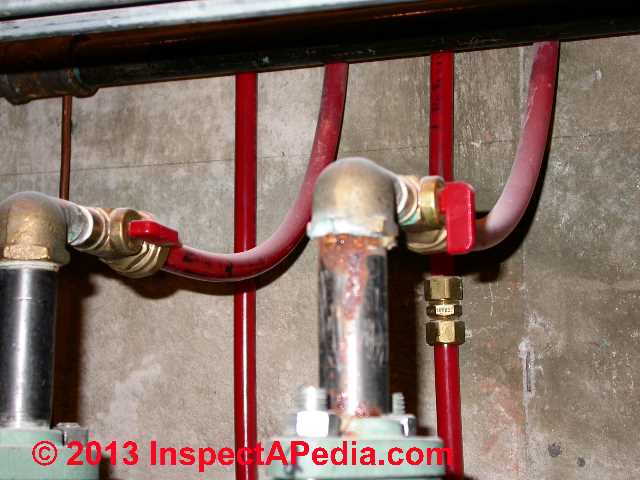
They being on the on/off valves for my heating system. I've attached a picture of it below- what Im referring to is the two red shut off valves- one on top between (now off) where water flows upstairs to the radiant flooring and the other below (between where the water flows to then basement heat)- also in off position.
My question is are these suppose to be in a off position or on position during regular heating? - J.C. 11/20/2013
Reply:
I need to see more of the piping in and out of the boiler and entering and exiting the room.
Are your baseboards or radiators all getting hot. Some? None?
What type of heating system are we looking at: baseboards, radiators, radiant?
Reader follow-up:
 On the right leads to the upstairs top floors radiant flooring. On the left is the return supply. I currently have both water valves closed. It seems to be working by heating up the house- but when they are closed this seems to only work for a day or two and then the floor-house cools down as if the heat is turned off?
I know this could be even an underlying issue wit h a part and might not even have to do with the two water tee shut off valves
[Click to enlarge any image]
Attached is the best i can do. On the right leads to the upstairs top floors radiant flooring. On the left is the return supply. I currently have both water valves closed.
It seems to be working by heating up the house - but when they are closed this seems to only work for a day or two and then the floor-house cools down as if the heat is turned off?
I know this could be even an underlying issue with a part and might not even have to do with the two water shut off valves .
But Im also worried by having them closed im doing damage to something by not letting water pass through the right way. The temp and psi pressue of the heater istelf has been constent and working. Sorry if to vague- thanks though for the reply and getting back to me nonetheless. Jake
Reply:
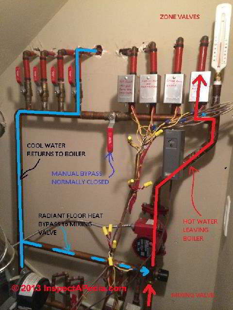
You need that valve shut, Jake, as far as I can make out. It seems to be a bypass valve. Based on noticing a red dot I see on the mixing valve that usually indicates the valve's "HOT" side, I think I've marked the water flow direction on an edited version of your photo immediately above.
[Click the labeled image above to see text details explaining the piping layout, bypass, mixing and zone valves.]
If I'm right about the water flow direction the system is laid out in a common pattern for radiant heat flooring systems, though in general we prefer to put the circulator and zone valves on the return side or cooler side of the heat piping loop where they may have a longer life. But since radiant heat systems flow cooler water through the valves, at least those fellows care less than in other hydronic heating system designs.
In any event, even if I'm wrong in my guess about direction of water flow, that valve between the zone valves and the return lines should normally be shut. That manual bypass is there for the service tech as an over-ride for the thermostatically controlled mixing valve labeled and shown in your photo at lower right.
Your system has a separate bypass and mixing valve (as I note in my edited photo) that tempers the hot water leaving the boiler with fairly warm water returning from the zones - a common practice especially where radiant heat floors are used but one also used in some other hydronic heating systems.
Finally, the fact that your system heats adequately at times and not others is basis for a service call to see what's going on with the controls.
...
Continue reading at RADIANT HEAT DEFECTS LIST or select a topic from the closely-related articles below, or see the complete ARTICLE INDEX.
Or see these
Recommended Articles
- RADIANT HEAT - home
- CARPETING IMPACT on RADIANT HEAT FLOOR
- DRIVEWAY & WALK DE-ICING SYSTEMS
- MIXING VALVE USE on RADIANT HEATING SYTEMS
- RADIANT HEAT AIR BOUND
- RADIANT HEAT CONTROLS
- RADIANT HEAT DEFECTS LIST
- RADIANT HEAT DESIGN & INSTALLATION MANUALS
- RADIANT HEAT INSTALLATION
- RADIANT HEAT MISTAKES
- RADIANT HEAT TEMPERATURES
- RADIANT HEAT TEMPERATURE CONTROL / MIXING VALVES
- RADIANT HEAT TEMPERATURE NIGHT SETBACK
- RADIANT SLAB FLOORING CHOICES
- RADIANT SLAB TROUBLESHOOTING
- RADIANT SLAB TUBING & FLUID CHOICES
- RADIANT SLAB TUBING LEAKS
- SLAB INSULATION, RADIANT / PASSIVE SOLAR
- THIN FILM RADIANT HEATING SYSTEMS for Ceilings & Floors
- WOOD FLOOR RADIANT HEAT
- WOOD FLOOR RADIANT HEAT DAMAGE
Suggested citation for this web page
RARadia CONTROLS at InspectApedia.com - online encyclopedia of building & environmental inspection, testing, diagnosis, repair, & problem prevention advice.
Or see this
INDEX to RELATED ARTICLES: ARTICLE INDEX to RADIANT HEAT
Or use the SEARCH BOX found below to Ask a Question or Search InspectApedia
Ask a Question or Search InspectApedia
Try the search box just below, or if you prefer, post a question or comment in the Comments box below and we will respond promptly.
Search the InspectApedia website
Note: appearance of your Comment below may be delayed: if your comment contains an image, photograph, web link, or text that looks to the software as if it might be a web link, your posting will appear after it has been approved by a moderator. Apologies for the delay.
Only one image can be added per comment but you can post as many comments, and therefore images, as you like.
You will not receive a notification when a response to your question has been posted.
Please bookmark this page to make it easy for you to check back for our response.
Our Comment Box is provided by Countable Web Productions countable.ca
Citations & References
In addition to any citations in the article above, a full list is available on request.
- Ralph Arlyck, Timed Exposures, Tivoli, NY. Mr. Arlyck is a documentary film maker and producer/director of Timed Exposures, an independent film production company, Timed Exposures has produced more than a dozen critically-acclaimed documentaries which span a broad spectrum of subjects. These films have been broadcast widely in the United States and Europe, and have won top prizes at American and international festivals. Email: ralph@timedexposures.com
- Steve Bliss's Building Advisor at buildingadvisor.com helps homeowners & contractors plan & complete successful building & remodeling projects: buying land, site work, building design, cost estimating, materials & components, & project management through complete construction. Email: info@buildingadvisor.com
Excerpts from his recent book, Best Practices Guide to Residential Construction, Wiley (November 18, 2005) ISBN-10: 0471648361, ISBN-13: 978-0471648369, appear throughout this website, with permission and courtesy of Wiley & Sons. Best Practices Guide is available from the publisher, J. Wiley & Sons, and also at Amazon.com - Calorique Radiant Heating Floor & Ceiling Systems, Calorique LLC, 2380 Cranberry Highway,
West Wareham, MA 02576 USA, Tel: 800 922-9276,
produces thin film radiant heating panel systems used for interior building heating (ceilings or floors), snow melting, de-icing, drum and tank heaitng, agricultural uses, pet heating systems, and consumer end products.
The company provides radiant floor heating systems in several designs including specifically for use below laminate flooring, carpeting, and tile floors. - Thanks to reader Jim O'Dowd for suggesting this resource. - Entran radiant heat:
- FloorHeat 3130 Sovereign Drive, Lansing, MI 48911, 888-265-5455, Email: info@FloorHeatCompany.com) radiant floor heating panels,
- Heatshield Panels, 27354 Valley Center Road, Valley Center, California 92082 USA, 800-750-3978
- Nuheat Industries, 3105 - 6900 Graybar Road, Richmond, BC Canada V6W 0A5, electric radiant heat systems for use under tile, stone, and laminate flooring, Web: nuheat.com Tel: 800-778-WARM (9276) Email: info@nuheat.com
- ASHRAE 25 Heating, Refrigeration, and Air Conditioning engineering standards
- ASHRAE 90.1-2004 User's Manual, instructions for the design of commercial and high-end residential buildings "to ensure their compliance with ANSI/ASHRAE/HESNA Standard 90.1-2004 including the application of principles of effective energy conserving design..."
- CarbonicHeat radiant heat flooring products, Web: carbonicheat.com Tel: 866.786.1806 Email: sales@carbonicheat.com, [no mailing address]
- Olesen, B.W., et al. 1980. “Thermal comfort in a room heated by different methods.” ASHRAE Transactions 86(1):34–48.
- Olesen, B.W. 1977. “Thermal comfort requirements for floors occupied by people with bare feet.” ASHRAE Transactions 83(2):41–57.
- Olesen, B.W. 1994. “Comparative experimental study of performance of radiant floor heating system under dynamic conditions.” ASHRAE Transactions 100(1):1011–1023.
- John Siegenthaler, is a professional engineer specializing in radiant heat designs and heat transfer theory in buildings. Mr. Siegenthaler principal of Appropriate Design, a consulting engineering firm specializing in hydronic heating design.
He is the author of Modern Hydronic Heating and Radiant Precision (available from the Radiant Panel Association (www.radiantpanelassociation.org, 800-660-7187). His work is discussed here
at
RADIANT HEAT MISTAKES (not John's mistakes, rather those of other radiant heat system installers) - In addition to citations & references found in this article, see the research citations given at the end of the related articles found at our suggested
CONTINUE READING or RECOMMENDED ARTICLES.
- Carson, Dunlop & Associates Ltd., 120 Carlton Street Suite 407, Toronto ON M5A 4K2. Tel: (416) 964-9415 1-800-268-7070 Email: info@carsondunlop.com. Alan Carson is a past president of ASHI, the American Society of Home Inspectors.
Thanks to Alan Carson and Bob Dunlop, for permission for InspectAPedia to use text excerpts from The HOME REFERENCE BOOK - the Encyclopedia of Homes and to use illustrations from The ILLUSTRATED HOME .
Carson Dunlop Associates provides extensive home inspection education and report writing material. In gratitude we provide links to tsome Carson Dunlop Associates products and services.
 | HOME | ABOUT | ASK a QUESTION | CONTACT | CONTENT USE POLICY | DESCRIPTION | POLICIES | PRIVACY | |
| © 2024 - 1985 Publisher InspectApedia.com - Daniel Friedman | |||||||||