
InspectAPedia® FREE Encyclopedia of Building & Environmental Construction, Diagnosis, Maintenance & Repair |
Question? Just ask us! InspectAPedia
|
 Guide to Stack Relay Switches on Oil Fired Heating Equipment
How the RA116A / RA117A / RA817A protectorelays work & are reset
- POST a QUESTION or COMMENT about oil heating equipment stack relay installation, diagnosis, repair, re-set procedure & replacement options
Stack relay switch guide for oil fired heating equipment:
In this article series, beginning here we explain how to inspect, test, reset, or clean the stack relay switch used as a flame detection/safety device for primary control on oil fired heating systems (boilers and furnaces). Included is an explanation of the operation of the Honeywell RA116A, RA117A, and RA817A protectorelays, a primary control that senses heat to confirm that the oil burner is operating successfully.
This article series answers most questions about central heating system troubleshooting, inspection, diagnosis, and repairs. We describe how to inspect, troubleshoot and repair heating and air conditioning systems to inform home owners, buyers, and home inspectors of common heating system defects.
InspectAPedia tolerates no conflicts of interest. We have no relationship with advertisers, products, or services discussed at this website.
A Guide to Stack Relay Control Switches on Boilers, Furnaces, or Water Heaters
Articl Contents
- DEFNITION of STACK RELAY SWITCH - PROTECTORELAY
- STACK RELAY MOUNTING POSITION
- STACK RELAY OPERATION
- STACK RELAY RESET BUTTON OPERATION
- STACK RELAY INTERNAL RE-STEPPING the CONTACTS
What is a "Stack Relay" or (Honeywell) Protectorelay switch and how does it work?
A "stack relay" is a primary heating system safety control mounted on the flue vent connector close to an oil fired heating boiler, furnace, or water heater.
This switch includes a bimetallic spring that responds to the presence of heat in the flue vent - indicating that the oil burner has achieved and is maintaining proper flame ignition.
If the stack relay does not sense successful ignition within a short period (typically 75 seconds), the switch "opens" to cut off line voltage to the oil burner, effectively shutting off the system to avoid a harmful or dangerous situation.
This switch handles loss of oil burner flame either at start-up or during ongoing operation of the heating appliance.
Following a safety shut-down, most stack relay switches must be re-set manually by pushing a reset button, illustrated and explained below.
Oil Burner Stack Relay Switches (Protectorelay® type controls), Detailed Explanation
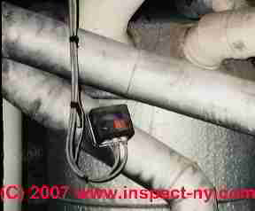
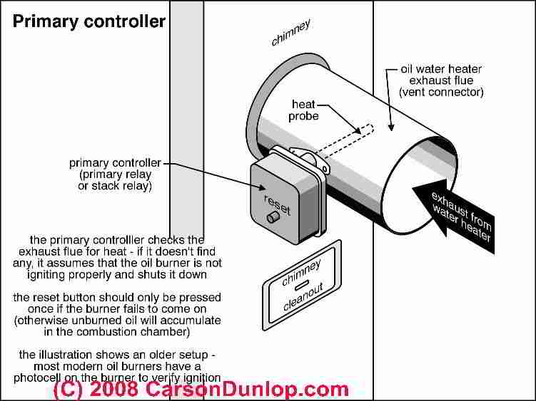
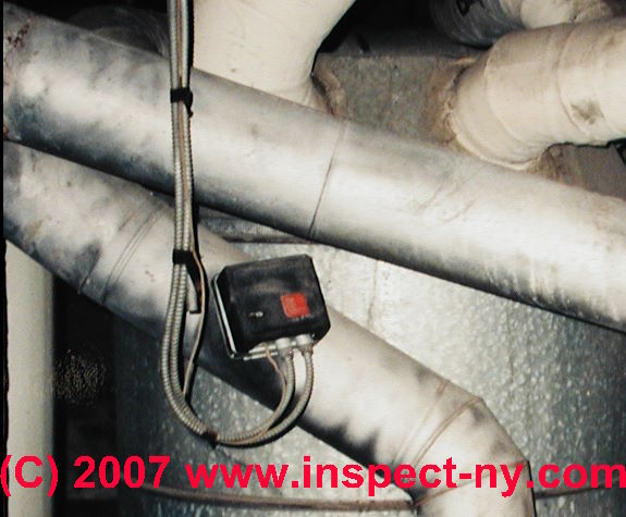
The stack relay switch shown in the photograph at page top and illustrated in Carson Dunlop's sketch, above, is attached at the flue vent connector which in turn passes flue gases from an old "octopus" type furnace to the chimney. (See the black box with its red reset button.) This same switch might also be found on some oil-fired heating boilers (hot water, hydronic, baseboard, or radiator heat) not just on furnaces (hot air heat)
Older oil burners used to heat a warm air furnace, a heating boiler, or a water heater may use a stack relay switch as a primary controller to prevent sending fuel into the oil burner if the oil burner flame has not been successfully ignited.
Stack relays are an older type of flame sensor than the CAD CELL RELAY SWITCH, but they accomplish the same purpose (turn off the oil burner if the flame is not established).
Where to Mount the Primary Control Protecto Relay or Stack Switch
The "stack relay" uses a bimetallic spring (also called a bimetallic helix) inserted into the flue vent connector located usually quite close to the heating boiler between the boiler top and the chimney.
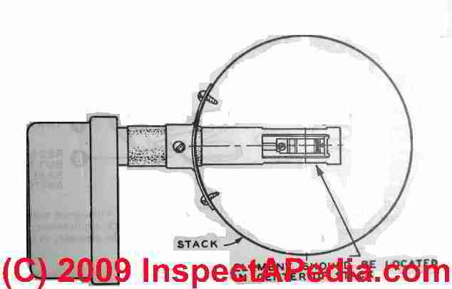
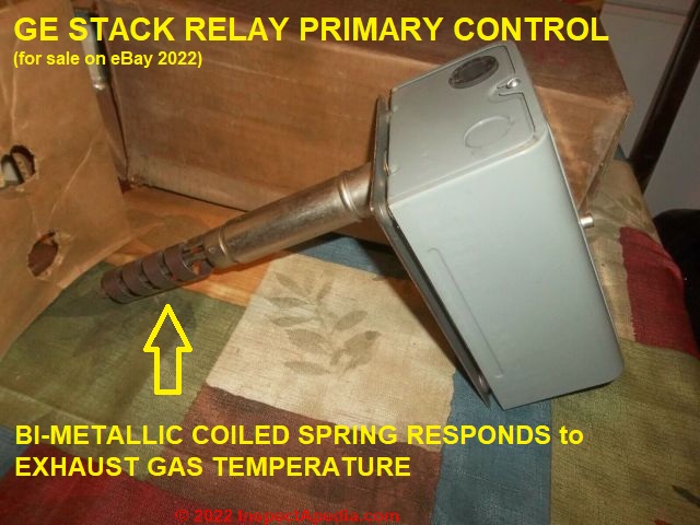
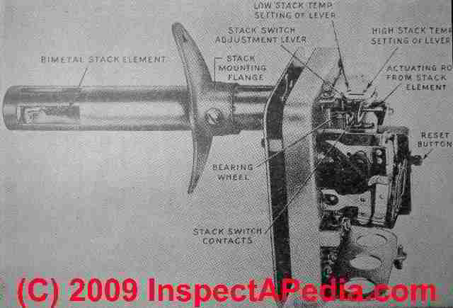
The round tube containing the bimetallic temperature sensing spring is inserted into the heating appliance flue stack so that it is located in the center of the path of flue gases. (Audel sketch at left, edited and illustrated below in this photo of a GE Stack Relay primary control where we show the bi-metallic spring key to the operation of this control).
Taking advantage of the fact that two different metals laminated together will expand at different rates, the bimetallic spring moves in response to the presence or absence of heat inside of the flue vent connector ("smoke pipe" or "stack") of an oil fired boiler or furnace.
Sensing heat in the stack is a means of assuring that the burner flame is present.
Protecto Relay RA116A RA116A RA817A Manuals
are given as PDF downloads at STACK RELAY MANUALS
How Stack Relay Safety Switches Work on Oil Fired Heating Equipment
How Stack Relay Switches Work: Older oil burners may use a Stack Relay to accomplish the same purpose (turn off the oil burner if the flame is not established).
The "stack relay" is a bimetallic spring inserted into the flue vent connector located usually quite close to the heating boiler between the boiler top and the chimney.
If the oil burner fails to ignite or if the flame is intermittent, too small an cool, or lost entirely, this safety control will sense the loss of oil burner flame by sensing the drop of temperature in the flue.
As the bimetallic spring changes shape in response to cooling, it mechanically operates a primary control safety-off switch to turn off the oil burner motor (so that we don't keep pumping un-burned heating oil into the combustion chamber).
Similarly to failure to ignite at boiler or furnace start-up, if the flame is lost during oil burner operation this control will also turn off the oil burner motor.
The Type RA 116A or Type RA117A primary control is also designed to automatically re-start the oil burner after a cool-down cycle of a minute to a minute and a half after an abnormal shutdown. If multiple re-start attempts fail to get the oil burner operating satisfactorily the system will shut down entirely in "SAFETY OFF" condition.
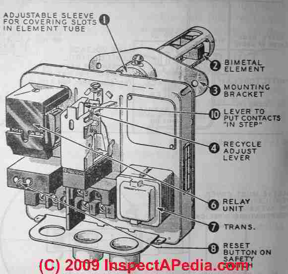
This control includes a red safety reset button (#8 in the drawing) that pops out if the control has caused a safety shut down of the oil burner. Here we explain when, how, and how-often to press the red reset button to try re-starting the oil burner.
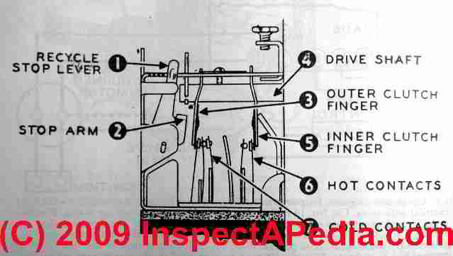
Our sketches (above from Audel) of a Type RA 116A / RA 117A Primary Control, also called a Stack Relay or a Protectorelay, shows the cover removed and identifies the principal components of this heating system control.
The Type RA 116A primary control was used on constant-ignition oil burners that fired heating boilers, warm air furnaces, and water heaters. You will still find this old control on older oil fired heating equipment, though not on newer oil-fired equipment which is more likely to use
a CAD CELL RELAY SWITCH Flame Sensor to detect the successful ignition of the oil burner.
The bimetallic spring warms in response to hot oil burner exhaust, confirming that combustion is taking place. If combustion is not occurring a timer inside the stack relay turns off the oil burner to prevent flooding of the combustion chamber with un-burned oil.
The stack relay switch shown in the page top photograph and in the sketch above is attached at the flue vent connector which in turn passes flue gases from an old "octopus" type furnace (in our photograph) to the chimney.
(See the black box with its red reset button.) This same switch might also be found on some oil-fired heating boilers (hot water, hydronic, baseboard, or radiator heat) not just on furnaces (hot air heat).
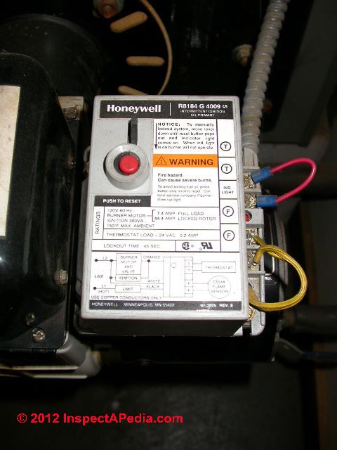
How to Reset the Honeywell Oil Burner Stack Relay - Using the Reset Button
 A gray box with a red reset button housing the stack relay and its reset switch will be found mounted
on the flue vent connector if this control is in use.
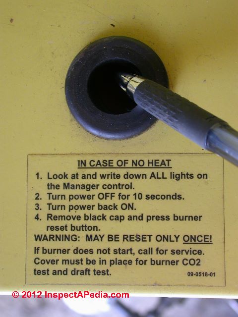
The first is simply to press the red reset button that protrudes through the cover of the stack relay box itself.
A gray box with a red reset button housing the stack relay and its reset switch will be found mounted
on the flue vent connector if this control is in use.
The first is simply to press the red reset button that protrudes through the cover of the stack relay box itself.
The primary control reset button on a Delco master control is labeled at the center right of the illustration at left. A primary control stack relay reset button is also pointed out by arrow #8 in our sketch above.
This red button should project through a small hole in the primary control's cover.
If you don't see the red button but you see the hole in the control cover, it's possible that a plastic reset button extension has broken off and been lost, but the actual working reset button and switch can still be found inside the control cover and it can still be pressed.
Knowing how to reset the stack relay can avoid a costly no heat service call or it can keep the heating boiler running sufficiently to keep the building warm while waiting for the heating service technician.
There are actually two resets that can be performed on an oil burner stack relay.
A second stack control reset might be necessary - we discuss it
at HOW TO RESET the Oil Burner Stack Relay below.
How many times can I press the reset button on the oil burner primary controller?
Watch out: Most heating technicians and inspectors will tell you to only press the reset button once. That's because we worry that a homeowner will keep pressing the button even though the oil burner flame is never igniting.
Watch out: sometimes the red plastic button on older heating equipment primary controls can break off.
At RESET SWITCH, HEATER REPAIR we show how to reset the equipment safely if this happens to you.
How do I Find the Reset Button on the Stack Relay?
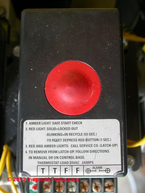
You can see the "reset button" illustrated in sketch earlier on this page. Note: the "reset button" on some primary safety controls is actually a round red button protruding through the control cover. Usually when the control has locked out the oil burner, this button "pops out" to project further through the control cover.
Using a cad cell relay as a model we illustrate that the safety control red reset button may be a small (5/16" diameter) round plastic button protruding up through the control cover (below left) or it may be a larger round red rubber button such as the cad cell reset switch (below right).
 ...
... 
Finding the Primary Control Reset Switch
Where the Heck Are The Various Reset Buttons on Heating Equipment?
If you are looking for the main reset button on heating equipment you'll want to see:
- AQUASTAT CONTROL FUNCTIONS and
- CAD CELL RELAY SWITCH (hot water boilers and some water heaters),
- STACK RELAY SWITCH On older oil fired boilers and furnaces, [This Article]
- FLUE GAS SPILL SWITCH TRIPPING & RESET (gas fired equipment), and
- LOW WATER CUTOFF CONTROLS On steam heating systems.
- At ELECTRIC MOTOR OVERLOAD RESET SWITCH we discuss the thermal overload switch and reset button that is found on many electric motors including those operating air conditioning fans, heating system oil burners, and furnace blowers and motors.
Watch out: on many primary controls, the red plastic reset button is actually a plastic button and spring-assembly mounted to the control cover itself.
Just to make things tricky, on some controls the reset switch is black and even recessed, such as on the Energy Kinetics cover shown at left.
But other manufacturers know we're seeing red if we've lost heat - and most of them make the reset button red.
Below we discuss other reset functions peculiar to the Stack Relay Switch, also called the Primary Controller on older oil fired heating equipment. But first we make a brief warning about puffbacks.
Oil Burner puffback Problems & Warning
Watch out: There is a reason that instructions for a homeowner tell you to push the primary heating control reset button just "once". If you keep pushing it the oil burner will indeed keep trying to start, spraying more heating oil into the combustion chamber at each "try".
If you flood the heater's combustion chamber with un-burned oil which later does ignite, the result can be a dangerous puffback which blows soot and smoke into the building, can damage the equipment, is unsafe, and could even start a fire.
So as with cad cell relays and other heating system "reset" buttons, if the oil burner does not turn on and run continuously and normally (no smoke, no loud noises, etc.) for at least 5 or 10 minutes after resetting the relay or pressing the reset button, DO NOT keep resetting the system since doing so can flood the combustion chamber with un-burned heating oil - a dangerous condition as we just explained.
See OIL BURNER SOOT & PUFFBACKS for details.
How to Reset the Honeywell Oil Burner Stack Relay - Using the Internal Relay Stepping Lever to Re-Step the control
 Why might you need to remove the cover and look for a second, "internal" reset lever inside of this control? Sometimes simply pressing the reset button through the cover of the stack relay switch will not turn on
the oil burner, but the problem could be in the switch itself, not the burner.
Why might you need to remove the cover and look for a second, "internal" reset lever inside of this control? Sometimes simply pressing the reset button through the cover of the stack relay switch will not turn on
the oil burner, but the problem could be in the switch itself, not the burner.
Honeywell explains:
The detector contacts are actuated by a friction clutch that is mounted on a rod connected directly to the heat actuated element. Occasionally, this clutch becomes out of step after a long period of idleness.
To place the clutch and the contacts in step [... you will need to pull and release the lever shown at left and explained below] [6]
This procedure is called "re-stepping" the Protectorelay or Type RA 116A Primary Control (which we call the "stack relay" because its bimetallic spring sensor is inserted into the oil-fired boiler or furnace "stack pipe" (flue vent connector) where it senses the heat from a successful oil burner ignition and flame.
This second and more thorough reset of the stack relay (after tying just pressing the reset button found on the switch cover) can be accomplished by removing the cover on this control box.
Watch out: (SAFETY WARNING LIVE VOLTAGE electrical connections are inside this box - a shock hazard
Simple Procedure to Re-step the Pyrostat Detector Relay
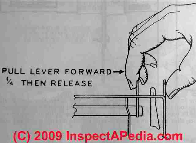 The stack relay bimetallic spring assembly can be "reset" by removing
the cover of the assembly and pulling the (visually obvious) reset lever out away from the flue vent connector (it will move about 1/4 of an inch), and then
carefully and gently releasing it again.
The stack relay bimetallic spring assembly can be "reset" by removing
the cover of the assembly and pulling the (visually obvious) reset lever out away from the flue vent connector (it will move about 1/4 of an inch), and then
carefully and gently releasing it again.
Put the cover back on and push the red safety reset button.
If electrical power is on to the system and if there is an oil supply and the oil valve is open, and if the thermostat is calling for heat, the oil burner should start.
Watch out for sensitive stack relays: sometimes these switches trip off during oil burner testing or operation and they can be tricky to re-set.
If you're able to get the system running again by using this internal reset, but if the relay switch tends to trip off if you simply tap on the outside of the relay switch when its cover has been replaced, then there is a problem needing further investigation, either with an electrical connection in the switch, or with the switch itself.
In this case the stack relay switch may need replacement, but before replacing it see our note below on cleaning the stack relay switch.
Watch out: Honeywell warns to be careful not to bend any of the switch parts such as contact arms or stops on the "pyrostat" detector mechanism (the bimetallic spring, relays, sensors) and also warns not to try making any adjustments other than those given in the installation instructions for the equipment.[6]
How to Re-set the GE Stack Relay Primary Control - Use the Reset Dial
The General Electric Master Oil Burner Control GE CR7865 A101B2, CR7865A101 was for sale on eBay in 2022. In our photo we mark the re-set dial and its simple instructions.
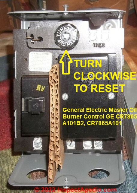
Remove the GE primary control cover, turn the dial at upper center towards the right, then release it. This will re-step the relay that is in turn controlled by the movement of the bimetallic spring that senses stack temperature.
Question: is there a high limit built into the RA-116 Stack Relay Control?
 (Oct 5, 2016) Bud said:
Really informative, Thank You, but no mention if there is a high limit built into the control, my old oil furnace control kicks out just before it reaches set temp on thermostat.
What would cause this? Filters dirty? Fan not blowing enough air? Bud budnpat@telus.net
Reply:
The stack relay only monitors stack temperature in an effort to confirm that the burner has ignited.
High temperature limits on a furnace like yours will be built into the fan limit switch.
A too-high plenum temperature ought to shut off the burner. But the stack relay typically used on older oil fired heating equipment will not, itself provide that additional function. As Honeywell explains in their publication on Oil Heat controls,
Critical Operations:
Failure to Light: If the burner fails to light, the cold contacts will not open. The safety switch will continue to heat until it trips and locks out. Flame Fails During Run Cycle: If the flame fails during the run cycle, the drop in stack temperature causes the detector’s hot contacts to open and drop out relay 2K, shutting down the burner.
After two to three minutes, the cold contacts close, energizing the safety switch heater. If the thermostat is still calling for heat, the burner and ignition will come back on to restart the burner. If a flame is not established within 70 seconds, the safety switch will lock out.
Other Notes:
As Fig. 14 shows, the stack relay uses one set of contacts in Start mode and another in Run mode. When the cold (Start mode) contacts are closed, they close the safety switch circuit, energizing the safety switch heater. When the hot stack gases heat the bimetal, the drive shaft moves, breaking the cold contacts (and the safety switch heater circuit) and making the hot contacts that complete the run circuit.
Thermal flame detectors may be separate from the primary control (as in the R8189/C550D combination that is continuing to be used although now obsolete) or included with the primary as in the RA117.
Whether it is included or separate, however, the very basis of the thermal relay is the Honeywell PyrostatÆ Flame Detector. The parts shown above are common to all Pyrostat® Flame Detectors although some details may vary.
The bimetal element is inserted in the stack where it is exposed to rapid changes in the temperature of the stack gases.
On an increase in stack temperature, the bimetal straightens, moving the drive shaft outward. This outward movement of the drive shaft is transferred to the hot and cold contacts through the clutch fingers.
As the drive shaft continues to move, the cold contacts are opened and the hot contacts are closed.
The clutch fingers ride on the drive shaft and must be free to slide, although there must be enough friction so they will move the contacts. If there is too much friction because of dirt buildup, the clutch fingers will not slide freely and the contacts will not be correctly sequenced.
The RA116 and RA816 Primary Controls and the C550D Detector have only one set of contacts that acts as both hot and cold contacts. The contacts must be closed when cold.
- "Controls for Oil Fired Heating", Honeywell Training Materials, Honeywell Controls, retrieved 2016/09, original source: customer.honeywell.com/resources/techlit/TechLitDocuments/71-0000s/71-97406.pdf
Reader Comments, Questions & Answers About The Article Above
Below you will find questions and answers previously posted on this page at its page bottom reader comment box.
Reader Q&A - also see RECOMMENDED ARTICLES & FAQs
On 2020-12-09 - by (mod) - try re-stepping the stack relay internal control
 John
John
Probably not.
I was looking for the case in which the burner runs, plenum heats up, fan starts, air flow is too weak, plenum gets too hot, system shuts down.
your case is probably a burner cleaning and adjustment issue, or potentially a bad wire, connection, relay, or control board.
By "Stack box" and by your identification of your primary control as the Honeywell RA117A, you're referring to what I call a stack relay - a primary control that monitors temperature in the flue vent connector, detailed at
STACK RELAY SWITCH
You will want to take a look at that article because it describes re-stepping the relay control - it an be a bit finicky.
Sometimes that's all that's needed to get the oil burner running properly again.
A stack relay is less reliable than a modern cad cell primary control, and can usually be replaced by a cad cell relay. There's a bit more to do - adding a cad cell eye and bracket in the burner assembly but any oil heat service tech ought to be able to do that.
Do me a favor and post a sharp photo of your stack relay as installed, and in a separate comment (one image per comment) a photo of the control with its cover removed. Be sure to see the warnings and details in the article I cited above.
This Q&A were posted originally at OIL BURNER WONT RUN
On 2020-12-09 by John
Upon further review, it's starts and stops before the blower ever gets going... Would that still be a filter issue... Also, if it is the stack box, is there a quick fix there... Those things are hard to find and very expensive... Thanks again for the help! It's a Honeywell RA117A
On 2020-12-09 - by (mod) -
Watch the limit control dial - if the furnace is shutting off on the HI LIMIT then it's overheating - possibly a dirty air filter, blocked air flow in ductwork, even a bad sensor.
On 2020-12-09 by John
Oil furnace short cycles for a bit, then will kick on as normal for a bit, then go back to short cycling. Been through everything with this "A Christmas Story" type furnace, just hoping it's something simple that I'm overlooking... It has an oil primary stack mount control, which looks ok. Thanks in advance.
On 2019-02-15 - by (mod) -
Jan
Watch out: DO NOT keep re-starting your oil burner; doing so when the unit has not run long enough to heat up and consume the startup spray of heating oil in the combustion chamber risks a dangerous PUFFBACK EXPLOSION at the boiler or furnace.
Clearly some service or repair is needed. I can't say from your note if the issue is a sooty RA117A stack relay, or a relay that has not bee properly re-set using its internal control lever, or perhaps improper, sooty oil burner operation.
Call your heating service company, tell them you have not heat and possibly an unsafe heating control, and ask for help from an experienced oil heat service technician.
Let us know what you're told and what the tech reports.
On 2019-02-15 by Jan
I have an old oil burner with a RA117A stack relay. I have no heat - when I push red reset button furnace fires up then shutts off after about a minute. Even aft a tech left relay pulled from flu, shld I cont. To push button
Reader comments:
(Aug 7, 2011) Dennis said:
very helpful information. Thank you
Question: is there a smoke measuring device that will give alarm if the oil burner is operating improperly?
Does anyone make a smoke measuring device, if stack smoke is out of a calibrated range it will alarm? To prevent puff backs. - Gerald 4/30/12
Reply:
Gerald
Presuming you are talking about measuring the level of smoke inside the flue vent connector of an oil fired heating appliance, the answer is of course.
A smoke tester, which uses a hand pump and filter paper, is standard equipment used by oil heat service technicians in testing and adjusting the combustion air and draft settings for the system.
There are also (much more expensive) electronic heating equipment test tools that measure all of the heating system tune-up parameters including temperature, CO and CO2 levels, draft, etc.
But those are manually operated devices used for system servicing, not devices that are permanently mounted to sound an "alarm" as you suggest.
Rather, different safety features on oil fired heating equipment monitor the flame itself, at the burner (a cad cell relay) or the temperature inside the flue vent connector (a stack relay). These primary safety controls will shut down the oil burner if improper conditions are detected.
Shutting down the equipment is what is needed, not sounding an alarm.
To prevent puffbacks be sure that your heating system is cleaned and serviced annually and that it is properly adjusted. That step will eliminate many but not all causes of puffbacks.
Read OIL BURNER SOOT & PUFFBACKS (article links listed at the ARTICLE INDEX the bottom of this article ) for details, and for advice on preventing puffbacks.
Question:RA116A won 't stay re-set
(Nov 17, 2012) larry lewis said:
I have a ra116a. turn the thermostat to 80 furnace will not start push the relay furnace runs fine till it reaches temp then shuts down but will not restart on its own. cannot read current at thermostat or at red and white terminals at ra116a.
11/11/14 Anonymous said:
Installed a new RA116A. At call for heat, the furnace starts and the pyrostat moves within the first 10 seconds and opens the contacts. Furnace runs with a clean crisp flame for about 5 minutes and then the red button trips. When the button trips the pyrostat is still at full extension and keeping the contacts open. Do I have a defective RA116A ?
(Oct 21, 2015) Darek said:
Hello I have Burnham oil boiler/ furnace I have to press reset switch to start the furnace every day then it runs good over night I think it a relay problem I can hear it click but unit doesn't start only after I press reset it has old Honeywell control
Reply:
Anon
Have you re-stepped the contacts? If pressing the external reset button doesn't fix a problem the RA116A or similar controls, you probably need to re-step the internal contacts. It's easy. Turn off the electrical power to the system, then
See
Darek: if re-stepping the contacts (described in the article above) doesn't fix this problem you need a professional service call.
...
Continue reading at STACK RELAY SERVICE & TEST PROCEDURES or select a topic from the closely-related articles below, or see the complete ARTICLE INDEX.
Or see these
Heating System Fire & Safety Control Articles
- CAD CELL RELAY SWITCH - test by using the safety switch, a small black plastic or metallic lever found next to the reset button on some primary heating system controls including stack relays and cad cell sensors.
- FIRE SAFETY CONTROLS
- OIL BURNER WONT RUN
- STACK RELAY SWITCH - home
- DEFNITION of STACK RELAY SWITCH - PROTECTORELAY
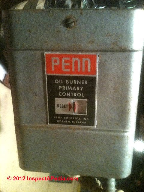
- PENN OIL BURNER STACK RELAY OPERATING DETAILS for a guide to a similar stack relay produced by Penn
- STACK RELAY MOUNTING POSITION
- STACK RELAY OPERATION
- STACK RELAY RESET BUTTON OPERATION
- STACK RELAY INTERNAL RE-STEPPING the CONTACTS
- STACK RELAY MANUALS
- STACK RELAY SERVICE & TEST PROCEDURES - separate article
- STACK RELAY, WHEN to CLEAN
- STACK RELAY DELAY TIME ADJUSTMENT
- STACK RELAY REPLACEMENT CROSS REFERENCE CHART - separate article
Suggested citation for this web page
STACK RELAY SWITCH at InspectApedia.com - online encyclopedia of building & environmental inspection, testing, diagnosis, repair, & problem prevention advice.
Or see this
INDEX to RELATED ARTICLES: ARTICLE INDEX to HEATING SYSTEMS
Or use the SEARCH BOX found below to Ask a Question or Search InspectApedia
Ask a Question or Search InspectApedia
Try the search box just below, or if you prefer, post a question or comment in the Comments box below and we will respond promptly.
Search the InspectApedia website
Note: appearance of your Comment below may be delayed: if your comment contains an image, photograph, web link, or text that looks to the software as if it might be a web link, your posting will appear after it has been approved by a moderator. Apologies for the delay.
Only one image can be added per comment but you can post as many comments, and therefore images, as you like.
You will not receive a notification when a response to your question has been posted.
Please bookmark this page to make it easy for you to check back for our response.
Our Comment Box is provided by Countable Web Productions countable.ca
Citations & References
In addition to any citations in the article above, a full list is available on request.
- [2]AUDELS OIL BURNER GUIDE, INSTALLING, SERVICING, REPAIRING, [PDF online copy of this book] Frank D. Graham, Theo. Audel & Co., New York 1946, 1947, 1955 (out of print, copies occasionally available from antique book dealers and on EBay). Use THIS LINK to read a free online copy of this helpful classic textbook.. Originally this 364 page guide to oil burner installation, operation, diagnosis, and repair sold for $1.00 - one dollar.
- [3] RA116A and RA117A Protectorelay®, Oil Burner Controls, Honeywell, 1985 Douglas Drive North, Golden Valley MN 55422-3992, Tel: 800-3456770 x 423, Website: customer.honeywell.com or in Canada: Honeywell Limited, 35 Dynamic Dr., Toronto, Ontario M1V 4Z9, website: www.honeywell.com, June 2000. Web search 4/3/2012, original source: http://customer.honeywell.com/techlit/pdf/63-0000s/63-9421.pdf
- [4] Domestic and Commercial Oil Burners, Charles H. Burkhardt, McGraw Hill Book Company, New York 3rd Ed 1969.
- Our recommended books about building & mechanical systems design, inspection, problem diagnosis, and repair, and about indoor environment and IAQ testing, diagnosis, and cleanup are at the InspectAPedia Bookstore. Also see our Book Reviews - InspectAPedia.
- In addition to citations & references found in this article, see the research citations given at the end of the related articles found at our suggested
CONTINUE READING or RECOMMENDED ARTICLES.
- Carson, Dunlop & Associates Ltd., 120 Carlton Street Suite 407, Toronto ON M5A 4K2. Tel: (416) 964-9415 1-800-268-7070 Email: info@carsondunlop.com. Alan Carson is a past president of ASHI, the American Society of Home Inspectors.
Thanks to Alan Carson and Bob Dunlop, for permission for InspectAPedia to use text excerpts from The HOME REFERENCE BOOK - the Encyclopedia of Homes and to use illustrations from The ILLUSTRATED HOME .
Carson Dunlop Associates provides extensive home inspection education and report writing material. In gratitude we provide links to tsome Carson Dunlop Associates products and services.
 | HOME | ABOUT | ASK a QUESTION | CONTACT | CONTENT USE POLICY | DESCRIPTION | POLICIES | PRIVACY | |
| © 2024 - 1985 Publisher InspectApedia.com - Daniel Friedman | |||||||||