
InspectAPedia® FREE Encyclopedia of Building & Environmental Construction, Diagnosis, Maintenance & Repair |
Question? Just ask us! InspectAPedia
|
 Water Feeders, Pressure Reducing Valves on Hot Water (Hydronic) Heating Boilers
Automatic boiler water feeder valves

- POST a QUESTION or COMMENT about heating boiler pressure reducing valves, water feed valves, check valves: operation and repair
Heating boiler pressure reducer valves - sometimes mis-named as boiler water feeder valves:
Here we explain hot water boiler (hydronic heat) pressure reducing valves and types of manual and automatic water feeder valves used on hot water heating boilers, including when and how to add makeup water to a boiler.
A chart illustrates the adjustment to heating boiler operating pressure as a function of building height or the number of floors in a building being heated.
We include photographs of common pressure reducer valves and water feeders used on hot water heating boilers to aid in product identification, links to installation manuals, safety warnings, installation and pressure reducer / water feeder safety and maintenance tips.
InspectAPedia tolerates no conflicts of interest. We have no relationship with advertisers, products, or services discussed at this website.
Hydronic (hot water) Heating Boiler Water Feed Valves
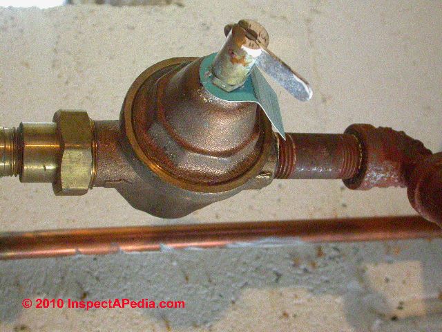
 The photo above shows a modern automatic pressure-reducing water feeder valve on a hydronic (hot water) heating boiler - one of the safety controls which we discuss in this article.
Contact us to suggest text changes and additions and, if you wish, to receive online listing and credit for that contribution.
The photo above shows a modern automatic pressure-reducing water feeder valve on a hydronic (hot water) heating boiler - one of the safety controls which we discuss in this article.
Contact us to suggest text changes and additions and, if you wish, to receive online listing and credit for that contribution.
[Click to enlarge any image]
Article Series Contents
- WATER FEEDER VALVE, HYDRONIC BOILER - CONTENTS: Water feeder valves & pressure reducing valves on hydronic (hot water) heating boilers - how to install, adjust, maintain, repair
- MANUAL WATER FEEDER VALVES ON HOT WATER BOILERS
- AUTOMATIC WATER FEEDER VALVES ON HOT WATER BOILERS
- AUTOMATIC HEATING SYSTEM AUTOMATIC WATER FEEDER BUILT-IN BACKFLOW PREVENTER
- IS THE B&G PRESSURE REDUCER AN AUTOMATIC WATER FEED VALVE
- ADD A LOW WATER CUTOFF SAFETY VALVE?
- MAKEUP WATER REQUIREMENTS - HYDRONIC HEAT VERSUS STEAM HEATING BOILERS
- PRESSURE REDUCING VALVE (AUTOMATIC WATER FEEDER) HAS TWO ADDITIONAL FEATURES
- PHOTO GUIDE TO HEATING BOILER PRESSURE REDUCING VALVES
- WATER PRESSURE SETTING FOR A PRESSURE-REDUCING VALVE OR WATER FEEDER ON A HOT WATER HEATING SYSTEM
- AUTOMATIC WATER FEEDERS BUILT-INTO EXPANSION TANKS
- PRESSURE REDUCING VALVE TROUBLESHOOTING, INSPECTION, SERVICE & REPAIR PROCEDURE
- PRESSURE REDUCING VALVE (BOILER) CLOG REPAIR
- PRESSURE REDUCING VALVE DISASSEMBLY
- PRESSURE REDUCING VALVE REPAIR KIT
- PRESSURE REDUCING VALVE WATER FEEDER INSTALLATION
Manual water feeder valves on hot water boilers
Hydronic (hot water boilers) in proper condition do not normally consume any water. Once the boiler and the baseboard, radiator, or convector piping are connected and filled with water, that same water remains in the system indefinitely.
The water in the boiler is heated and circulated through the occupied space to provide heat to the building occupants.
Water may be lost from a hot water heating system, however, due to a small leak that may be un-noticed, or water may be removed from the system during servicing.
Some older heating systems may not have an automatic water feeder and may only provide a manually operated valve to add water to the boiler. To maintain the water level in these heating systems, water can be added from the building water supply piping manually by simply opening a make-up valve.
A manual valve will simply be a shutoff valve that can be opened by hand to force water into the heating boiler.
Automatic water feeder valves on hot water boilers
 On many heating boilers
the expansion tank and water feeder valve are separate physical units.
On many heating boilers
the expansion tank and water feeder valve are separate physical units.
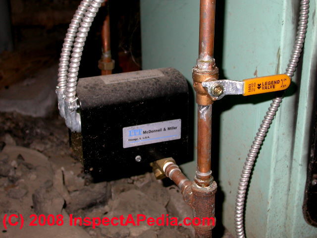
On these older systems the "automatic water feeder" is often a bell-shaped device which opens and sends makeup water into the heating boiler and its piping whenever the heating system's internal water pressure falls below a normal level (perhaps 12 psi when the boiler is cold).
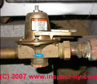
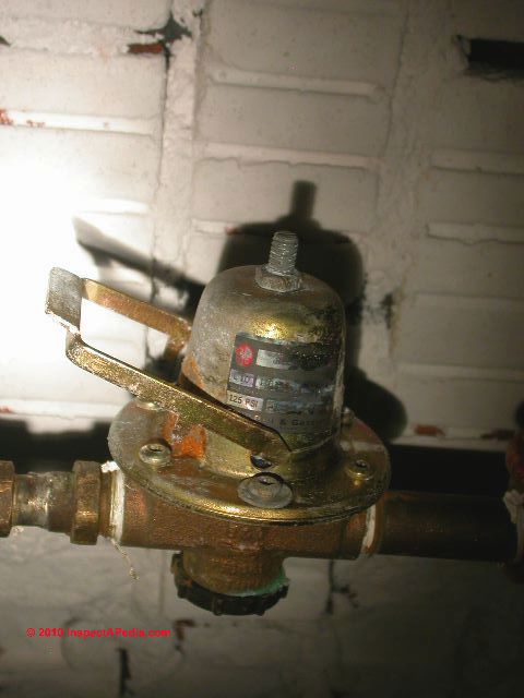
In our photo at left the gold colored bell-shaped device pointed to by the red arrow is an automatic pressure-reducing & water feed valve for a hot water boiler.
An arrow cast into the valve base shows the direction of water flow (from building supply at right into the boiler at left in this photo).
The screw and lock nut on top of this valve permit adjustment of the automatic water feeder valve pressure (it's normally set to 12 psi).
The horizontal lever is a bypass that will send water through the valve on to the boiler at full building pressure (it's normally left "off" in the position shown here).
The separate heating system backflow preventer / check valve indicated by our green arrow in the photo above is discussed in more detail
at BACKFLOW PREVENTER VALVE, HEATING SYS.
Automatic Heating System Automatic Water Feeder Includes Built-In Backflow Preventer
The device to the right of the automatic pressure reducer (water feed valve) in our photo above is a back-flow preventer that is required in some municipalities. The back-flow preventer makes sure that water from inside the heating boiler cannot flow backwards into the building (and community) water supply. This prevents back-contamination of potable water piping from the boiler should the building water pressure fail.
See CHECK VALVES, HEATING SYSTEM for more information about backflow preventers and other heating system check valves.
 An automatic water feeder used on hot water heating boilers performs two functions:
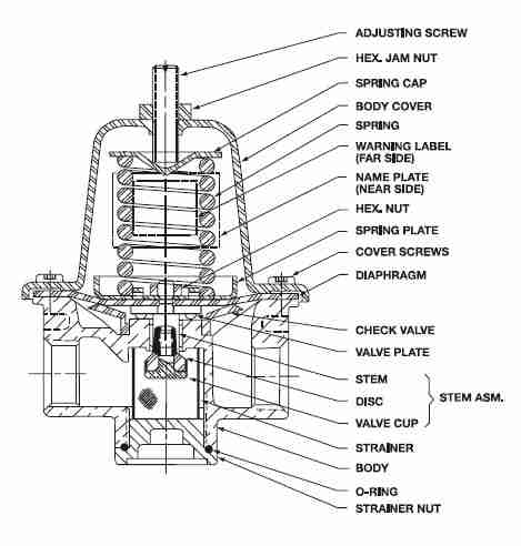
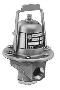
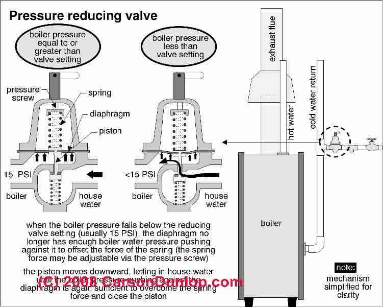
Bell & Gossett's sketch of their pressure reducing valve is shown at left.
- The automatic water feed valve reduces the incoming water pressure from the building supply side down to (typically) 12 psi.
That's because the normal in-boiler water pressure, when the heating boiler is cold, is about 12 psi in a normal residential system. A tall building may need to start with higher cold-system water pressure to be able to push hot heating water to upper floors.
[click to enlarge any image] - The water feed valve adds water to the boiler when needed: If water pressure in the heating boiler drops below 12 psi, the water feeder valve will add makeup water to the system automatically, until it reaches 12 psi inside the boiler.
So is the B&G Pressure Reducer an Automatic Water Feed Valve or Not?
Well yes, and no. The valve can automatically feed water into a hot water heating boiler whose pressure falls below the set-pressure (12 psi at factory setting) if the water shutoff valve for the boiler has been left "on".
The B&G pressure reducing valve shown at left includes a bypass lever shown in the "up" or "open" position in the illustration. In this position water is fed into the boiler at street pressure.
When the valve is "down" in the "closed" position, IF the shutoff valve before the pressure reducer is open, water is fed to the boiler if its pressure drops below the valve's pressure setting (adjusted by the lock-nut and screw on the valve top).
But the manufacturer warns that the purpose of the pressure-reducing (and automagic water feeding) valve is to fill heating boilers after installation or servicing. The company says
"It is not a safety device and is not intended to be used as as a water feed valve to control boiler water at a safe operating level".
OPINION: this is interesting since for closed-system hydronic heating boilers (not steam boilers) that's how lots of service techs and inspectors view this device.
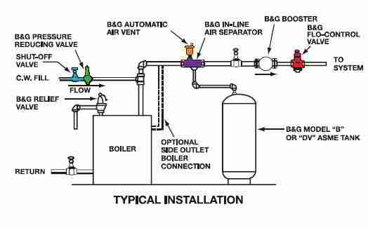
In the company's service manual you'll see on the installation piping sketch (edited) for the pressure reducing valve (green, to the right of the blue shutoff valve at the left side of the sketch below) that they expect the installer to include a water shutoff valve (blue at the left end of the sketch below) before this pressure reducer.
Keep the manual water feed shutoff valve closed?
B&G wants you to keep the boiler water supply valve shut except during service - as a precaution that allows easy detection of a boiler leak by noticing the reduced water pressure in that system.
The company also points out that too-frequent feeding of water into a heating system can increase the effects of corrosion and system damage.
In my [DF] opinion, a typical building owner or occupant almost never thinks to check the water level in a hydronic heating system (hot water boiler) until there is some indication of a problem (like no heat or a damaged leaky boiler).
 In our experience most hydronic heating boiler installers and service techs leave that shutoff valve "open" or "on" so that the boiler won't be at risk of being ruined or unsafe by operating at low or no-water level - their experience may be similar to mine.
The manufacturer is telling you what's safe in some regards, but they may not have the same view of what people actually do in the field.
Add a low water cutoff safety valve
A safety improvement on hydronic boilers that gets around this argument is to add a low-water cutoff on residential hydronic heating boilers (hot water heating boilers).
That device, always present on steam boilers, is required by local codes in some jurisdictions for hydronic heating boilers too.
See LOW WATER CUTOFF VALVES.
OPINION: on a hot water heating boiler that does not have a low-water cutoff valve installed, we would be reluctant to leave the building unattended for weeks or months during the heating season with the boiler water supply shutoff valve in the closed position.
We would think about leaving the water supply valve open - not what B&G recommends. That way if a small leak develops we're not at risk of destroying the boiler by firing it without adequate water in the system.
This violates the B&G installation instructions for their pressure reducing valve - so be sure to review this concern with your trained, heating service company service manager.
Differences in Makeup Water Requirements - Hydronic Heat versus Steam Heating Boilers
In normal use, a hydronic or hot water heating system does not consume any water. Only if there is a leak (or during service) would the water level in a hot water heating system drop and need replenishment.
That is an abnormal condition, and one that means the system needs to be repaired.
Keep in mind that devices like the B&G Pressure Reducer (notice they don't call it a "water feeder" even though it feeds water to the boiler) is intended for hot water or hydronic heating boilers.
But a hot water heating system might have a tiny, small, even hard-to-find water leak that goes un-noticed for some time, especially if the boiler water supply valve is kept open so that the pressure valve also feeds a little makeup water into the boiler when needed.
Conversely, on a steam heating system the boiler is expected to consume water at every operating cycle - the feed frequency is therefore much greater on a steam boiler and this B&G pressure reducer/water feeder would not be the proper device to use for water feeding.
For water feeders used on steam boilers,
see WATER FEEDER VALVE, STEAM.
The Pressure Reducing Valve (automatic water feeder) has two additional features:
- Pressure Reducing Valve Override: Lifting the lever over the valve body (B&G valve shown at page top) will overcome the 12-psi feature and force water into the heating boiler at building pressure.
This feature is not normally used, but it's useful during some service procedures such as refilling a boiler that has been drained (more rapidly than otherwise) or for temporarily forcing water into a heating boiler at high pressure for diagnostic reasons or to attempt to force air out of an air-bound hot water heating system.
Watch out: forcing cold water into a hot heating boiler can cause it to crack or be ruined.
Keep this "shutoff valve" or override lever closed except during initial filling of the boiler or when manually adding fill to a cool or cold boiler as part of service.
Installing the proper automatic pressure reducer water feeder should prevent this problem by feeding water to the boiler before boiler water pressure (or level if proper controls are added) is too low, and at a slow enough rate.
As B&G puts it NEVER ADD WATER TO AN OVERHEATED BOILER. Failure to follow those instructions could result in serious personal injury or death and property damage.
Watch out: constant addition of fresh makeup water to a heating boiler that is leaking can make discovery of the leak more difficult, and by constantly introducing fresh water, can lead to mineral deposits, clogging, or boiler damage.
Watch out: take a look at the funny lever position on the pressure reducing valve in our photo (above-left). Is it closed, off-bypass (down) or is it partly open (up)? We weren't sure, but this very valve was blamed for a major house flood causing thousands of dollars in damage from mold.
The building was unattended and the valve fed water into the structure for days, resulting in flooding and mold contamination. We wondered if the house-watcher made a mistake or was messing around with this device before the flood.
Watch out: yep one more. The manufacturer warns that
The Bell & Gossett Pressure Reducing Valve is designed for filling hot water boilers and associated piping systems to a properly controlled pressure after boiler installation or system servicing.
It is not a safety device and is not intended to be used as a water feed valve to control boiler water at a safe operating level.
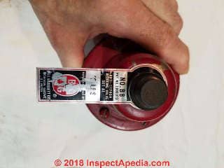
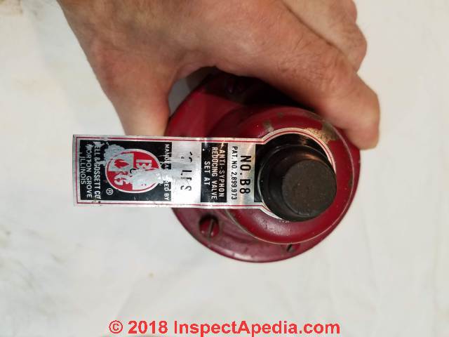
They are factory set at specified limits although adjustment is easily made. They are equipped with a built-in strainer and low inlet pressure check valve. [4] - Pressure Reducing Valve Set-pressure Adjustment: The incoming water pressure setting of 12 psi can be adjusted up or down by the service technician.
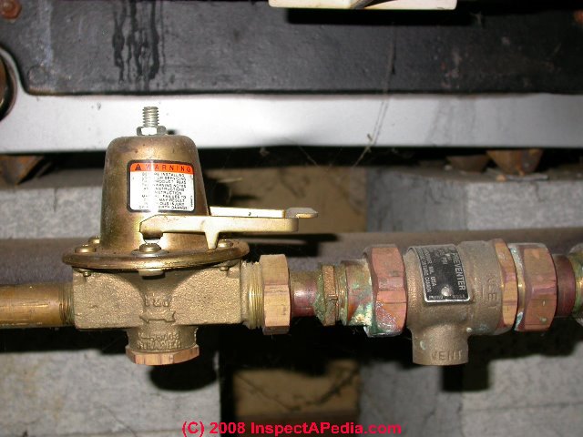
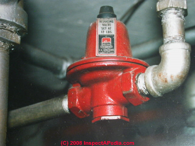
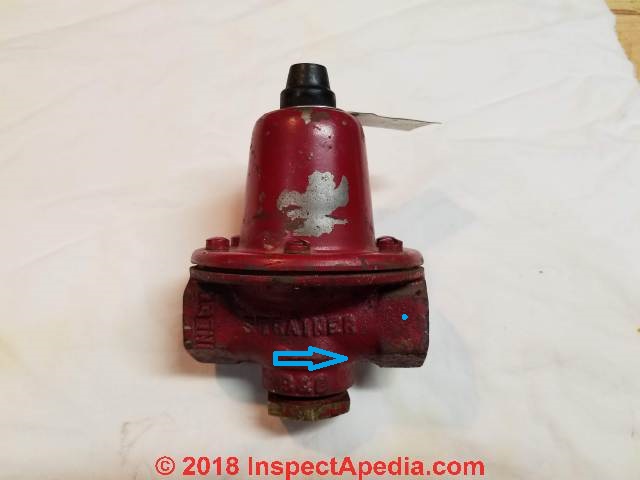
The red Armstrong™ pressure reducing valve shown here includes a black plastic cap covering its adjustment screw under the black plastic cap on top of the valve.
You'll see a similar screw (and lock nut) on the B&G water feeder valve in the photos above on this page.
Loosening the lock nut and then turning the screw on the top of the pressure-reducing valve "in" or "clockwise" increases the set pressure of the control. See B&G's "Reducing Valves Installation, Operation, & Service Instructions" linked-to
atReferences or Citations below.
Photo Guide to Heating Boiler Pressure Reducing Valves
 ...
... 
[Click to enlarge any image]
Our photo at above left shows an Armstrong™ pressure reducing valve. The schematic at above right, courtesy of Carson Dunlop Associates, explains how this pressure reducing valve works.
Our photo (left) shows another model of pressure reducer valve on the water supply line to an Energy Kinetics oil fired heating boiler.
The lever on the top of this valve combines a full-open bypass (when the lever is vertical) and a set-pressure adjusting locknut (below the round lever body).
Safety note: If the pressure reducing valve is combined with a pressure relief valve, for safety these parts must be installed in the correct position.
As Carson Dunlop Associates shows in the sketch above,
and as you'll also see in the B&G installation piping sketch,
the pressure relief valve should always be installed closest to the heating boiler so that it can respond to an overpressure in the heating system.
What is the proper water pressure setting for a pressure-reducing valve or water feeder valve on a Hot Water Heating System?
 What is the normal operating pressure of a hot water heating system boiler?
Hydronic heating systems (hot water) typically operate at about 12 psi cold and see a pressure increase to somewhere just under 30 psi when the system is at maximum temperature.
If you set the water feeder pressure too high it's likely that when the boiler heats-up to operating temperature, the water pressure will exceed the safety limit (30 psi) and the boiler relief valve will open to discharge excess pressure and water.
[click to enlarge this or any image]
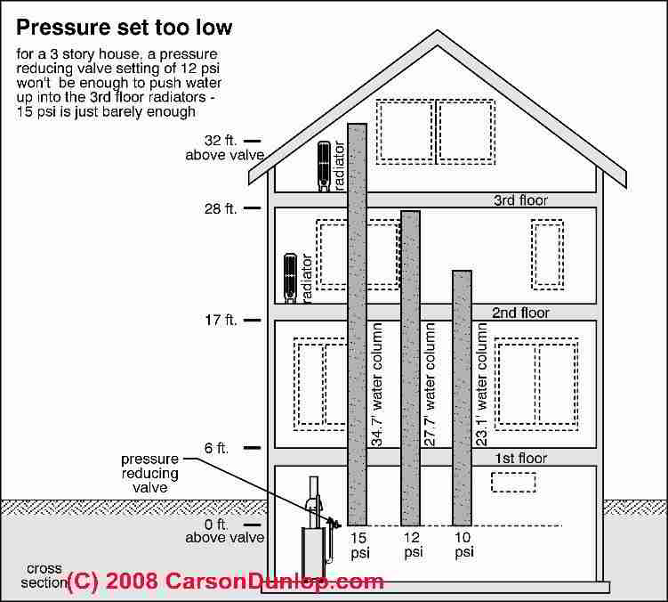
Because a hydronic heating system's circulator pump has little "lift" capacity (it just pushes the water around the loop of boiler and heating piping and radiators), the heating system depends on its internal water pressure to lift hot water to radiators (baseboards, or convectors) on upper floors in the building.
A higher building may therefore need higher heating system water pressure in order to be able to circulate heat adequately to upper floors.
The sketch, courtesy of Carson Dunlop Associates, explains that a three-story building will need heating system pressure set up to at least 15 psi. when the heating boiler is cold.
But in most cases you should leave the water feeder at the psi set by the installer (typical factory setting is 12 psi) unless the building has unusual conditions (such as more than two stories) that require a higher in-boiler starting water pressure.
Automatic Water Feeders Built-Into Expansion Tanks
 An automatic water feeder valve is included as part of some heating system expansion tanks on hydronic heating boilers - in a single unit such as those provided by Amtrol™, Extrol™, Fill-Trol™, or
similar expansion tanks.
An automatic water feeder valve is included as part of some heating system expansion tanks on hydronic heating boilers - in a single unit such as those provided by Amtrol™, Extrol™, Fill-Trol™, or
similar expansion tanks.
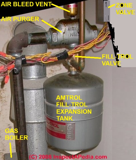
The water feeder is the brass assembly found attached to the expansion tank where piping from the boiler enters the tank on these units.
In our photo at left you can see the brass valve on top of the Fill-Trol™ expansion tank and underneath the cast iron air purge valve (red arrow).
The vertical copper pipe is feeding water from the building supply, at building water pressure into the brass valve and through it, upwards into the heating system distribution piping through the silver painted cast iron air purge valve.
This automatic water fill valve is not adjustable by the consumer and is factory-set to add water to the heating boiler whenever the system pressure falls below 12 psi.
The tank below the red arrow is, of course, an expansion tank. We discuss expansion tanks and their troubleshooting or maintenance
at EXPANSION TANKS.
Steam Boiler Water Feeder Valves, Automatic & Manual
 Details about automatic water feeders for steam heating boilers are
at WATER FEEDER VALVE, STEAM. Excerpts are just below.
Keeping the proper amount of water in a steam boiler is a critical function for both safety and to avoid damaging the boiler itself. So on a steam boiler we consider the automatic water feeder to serve as a safety device too. Water feed valves on steam heat systems operate under very different requirements than those on hot water (hydronic) heating systems.
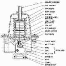
Automatic water feed valves on steam boilers (such as the McDonnell & Miller automatic water feeder shown at left) perform functions similar to the valve described earlier for hot water boilers.
Residential steam heating systems are mostly "low pressure" systems operating at less than 2 psi.
In fact if you see the pressure set higher on a residential system it is often an indicator that the occupants/technician have been having trouble getting the steam heat to locations where it's needed.
All steam heat systems all consume some water which escapes from radiator air vents during the time that the steam (heat) is first rising in the building. So unlike a hydronic water feeder, the steam boiler water feeder is going to be much busier, regularly adding makeup water to the steam boiler, but operating at low water pressures.
Steam heating systems without an automatic water feeder are less safe and risk serious boiler damage should boiler water be lost and should there be no low water cutoff installed on the system.
That's why all modern steam heating boilers can be expected to include at least a low water cutoff valve.
Low water cutoff valves are discussed in detail
Pressure Reducing Valve Troubleshooting, Inspection, Service & Repair Procedures
 Inspect & Check the Pressure Reducer for Proper Operation, Clean the Strainer if Needed
B&G offers some excellent tips on how to check the pressure reducer for proper operation, and how to fix some common problems.
- Check for corrosion, damage, or leaks at the pressure reducing valve.
Watch out: if you find corrosion, damage, or leaks at the pressure reducer valve, these should be taken as a very serious warning that the valve is about to cause serious damage, leakage, rupture, and unsafe conditions.
This valve should be inspected periodically, in our OPINION [DF] no less than at annual heating system service time. Unsafe heating equipment or controls can cause injury, death, or property damage. - Check to see if the valve is feeding water into the boiler: feel the temperature of the pressure reducer valve body: put your hand on the bell-shaped body of the pressure reducer or on the piping before and after the valve.
If the metal is cold to the touch in those areas, then the valve is "passing water" into the heating boiler.
This should not be happening if at the same time the heating boiler is already up to its operating temperature.
Possible causes:- improper reducing valve pressure setting
- a leak "downstream" from the pressure reducing valve, in the heating system piping or boiler or its controls
- a faulty pressure reducing valve that is not closing when it should - we illustrate this problem
at PRESSURE REDUCING VALVE DISASSEMBLY
Where you will see the strainer on the valve was completely clogged and the valve's internal moving parts were jammed solid. - A tankless coil leaking into the boiler - nothing to do with the pressure reducer
see TANKLESS COIL INTERNAL LEAKS INTO the BOILER
- If the relief valve on the heating boiler periodically leaks or discharges water, on a hydronic heating system (hot water boiler) the expansion tank may be waterlogged - losing the "air cushion" intended to accommodate thermal expansion.
Details offering more thorough diagnostics are
at RELIEF VALVE, TP VALVE, BOILER
and
at RELIEF VALVE, TP VALVE, STEAM BOILER and of course
also
at EXPANSION TANKS.
But one tip for waterlogged expansion tanks that use an internal bladder is one we hand neglected to mention: pump a bit of air into the expansion tank,
then put a dab of water (we recommend spit) on the opening of the air valve found on the bladder-type expansion tank. If the spit bubbles the valve is leaking.
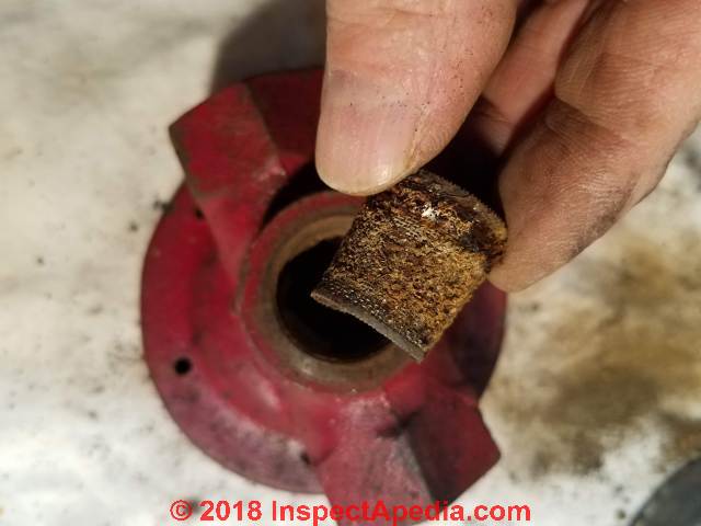
- Check for a clogged strainer in the Pressure Reducer/Feeder Valve
if the pressure reducer will not feed enough water into the boiler to reach the desired cold-pressure setting, before messing with re-adjusting the valve's feed pressure nut and screw, consider that the internal strainer in the valve may have become clogged.
See details about dis-assembling a pressure reducer to remove and clean or replace its strainer
at PRESSURE REDUCING VALVE (BOILER) CLOG REPAIR
Water Pressure-Reducing Feed Valve Inspection Tips
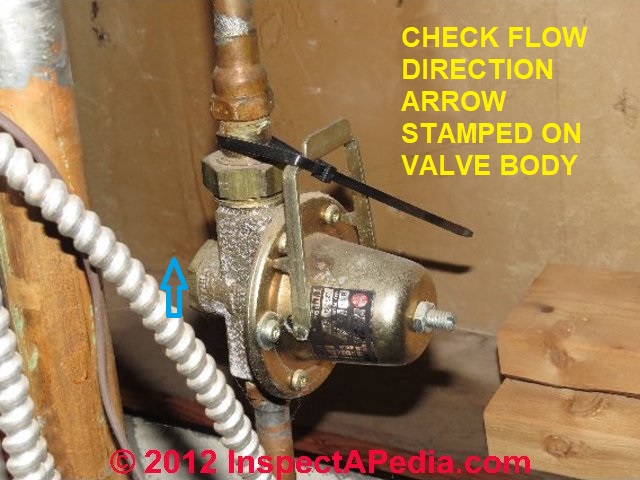
 Reader Question: What should we report if finding a water feed valve tied off as shown in this photo?
Tom Sherman - President, Absolute Home Inspection, Inc., 315-673-1755 provided this photo of a tied-off pressure-reducer water-feed valve and asked what we'd say about it, for an ASHI home inspector newsletter.
Home inspectors are expected to be competent to recognize conditions at a home that are improper, unsafe, not functional, etc. provided that the problem or component is readily accessible, visible, and under some other conditions.
In this photo we have a pressure-reducing water feed valve typically used on a hot water or hydronic heating system.
The valve valve, this one is a B&G model, has the job of feeding makeup water to the heating boiler should the water pressure in the heating system fall below the set-pressure on the valve - typically 12 psi for most one or two story residential buildings, though the set pressure may need to be higher in taller structures.
The water feed valve's override lever in the photo has been secured to the water pipe by a black plastic tie.
The override lever is used to put the water feed valve into "bypass mode" by lifting the lever to a 90-degree position above the water piping and valve body - meaning that the valve is manually forced "open" to allow water to enter the heating boiler at whatever pressure is on the inlet side of the valve.
(The heating boiler, not shown here, is always on the outlet side of the valve, and on most of these controls an arrow cast into the valve body indicates the intended direction of water flow.
In our photo we've drawn a blue arrow showing the direction of water flow for this valve. Click the image to see an enlarged version.
If the valve were in manual OPEN mode, the lever would be at right angles to the piping and valve body - its handle would be over the adjustment screw shown in the center of the valve top. So this valve is in the CLOSED position.
Why would someone put a plastic tie on the automatic water feed valve override lever to hold it in the CLOSED position?
Perhaps the heating service technician was annoyed by an owner's emergency service call complaining that the pressure / temperature relief valve was spilling and perhaps the tech found that the owner had been messing with the valve and over-pressurizing the boiler. If you set the boiler water pressure too high when cold then when the boiler heats up the pressure will exceed the (roughly 30 psi) pressure at which the relief valve will open.
But a more likely reason this valve was tied OFF or CLOSED was that it was leaking, feeding excess water pressure to the boiler on its own. One of the failure modes of these valves is that the valve begins to feed water when it should not. That can happen due to dirt and debris in the valve or for other reasons. Someone was trying to force the valve to behave itself.
Functional & Safety Worries with a Bad Behaving Water Feed Valve
Watch out: this is not only an improper heating system operating setup, it is potentially (though subtly) quite dangerous:
- If the valve has to be tied shut because it was feeding water when it shouldn't it needs to be repaired or replaced. But there's more to consider:
- If the boiler has been suffering from overpressure, causing the relief valve to spill frequently, there is a risk that the relief valve will have become clogged with mineral deposits - which in turn can cause the valve to fail to open in a true overpressure or over temperature emergency - the result can be a BLEVE or boiler explosion!
- If the homeowner has been opening this valve, for example during a DIY attempt to correct an air bound heating system, I'd give him or her a good spanking. And if there indeed has been a recurrent problem with the heating system becoming air-bound,
I'd look further for a problem with the automatic air bleed valve(s) that should be found at strategic locations on the boiler itself and perhaps on some sections of baseboards or other heat radiating devices. - If I were the service person, I would replace this water feeder, and I would either satisfy myself about the condition of the pressure / temperature relief valve (including that it has not been spilling) or I'd replace that part as well.
- The maintenance of proper water level and pressure in a hydronic heating boiler and its piping is critical not only for proper delivery of heat to the building, it is also critical to avoid overheating, damage, and unsafe operation should the boiler water level drop too low or be lost entirely.
Watch out: The manufacturers of this type of automagic water feed valve recommend that additional manual control valves be included in the piping system, so in some installations you might also find that the automatic water feeder is not really so automatic.
... the manufacturer warns that the purpose of the pressure-reducing (and automagic water feeding) valve is to fill heating boilers after installation or servicing. The company says
"It is not a safety device and is not intended to be used as as a water feed valve to control boiler water at a safe operating level".
Which is pretty interesting since so many people in the trades as well as among inspectors consider it a safety device.
This article series answers nearly all questions about Heating System Boiler Controls on central heating systems to aid in troubleshooting, inspection, diagnosis, and repairs.
How to Install an Automatic Pressure Reducing Valve / "Water Feeder"
The discussion of how to install a pressure reducer / water feeder has moved
to PRESSURE REDUCING VALVE WATER FEEDER INSTALLATION
The discussion of how to fix a clogged pressure reducing valve has moved
to PRESSURE REDUCING VALVE (BOILER) CLOG REPAIR
...
Continue reading at PRESSURE REDUCING VALVE WATER FEEDER INSTALLATION or select a topic from the closely-related articles below, or see the complete ARTICLE INDEX.
Or see WATER FEEDER VALVE / PRESSURE-REDUCER FAQs - questions posted originally at this page
Or see these
Recommended Articles
- CHECK VALVES, HEATING SYSTEM
- PRESSURE REDUCING VALVES
- PRESSURE REDUCING VALVE (BOILER) CLOG REPAIR
- PRESSURE REDUCING VALVE DISASSEMBLY
- PRESSURE REDUCING VALVE REPAIR KIT
- PRESSURE REDUCING VALVE WATER FEEDER INSTALLATION
- STEAM BOILER FLOODING / SURGING REPAIR
- WATER FEEDER VALVE, HYDRONIC BOILER - forced hot water heat
- WATER FEEDER VALVE, STEAM - steam heat: yours is a steam boiler
Suggested citation for this web page
WATER FEEDER VALVE, HYDRONIC BOILER at InspectApedia.com - online encyclopedia of building & environmental inspection, testing, diagnosis, repair, & problem prevention advice.
Or see this
INDEX to RELATED ARTICLES: ARTICLE INDEX to HEATING SYSTEMS
Or use the SEARCH BOX found below to Ask a Question or Search InspectApedia
Ask a Question or Search InspectApedia
Try the search box just below, or if you prefer, post a question or comment in the Comments box below and we will respond promptly.
Search the InspectApedia website
Note: appearance of your Comment below may be delayed: if your comment contains an image, photograph, web link, or text that looks to the software as if it might be a web link, your posting will appear after it has been approved by a moderator. Apologies for the delay.
Only one image can be added per comment but you can post as many comments, and therefore images, as you like.
You will not receive a notification when a response to your question has been posted.
Please bookmark this page to make it easy for you to check back for our response.
Our Comment Box is provided by Countable Web Productions countable.ca
Citations & References
In addition to any citations in the article above, a full list is available on request.
- [1] Thanks to Mark Cramer, Tampa Florida, for assistance in technical review of the "Critical Defects" section and for the photograph of the deteriorating gray Owens Corning flex duct in a hot attic. Mr. Cramer is a Florida home inspector and home inspection educator.
- [3] B&G Flo-Control Valves - installation, operation, and service instructions manual - original source Bell & Gossett, 8200 N. Austin Ave., Morton Grove IL 60053, USA - Tel 847 966-3700 Fax 847 965-8379 . www.bellgossett.com/BG-Literature-Detail.asp?LiteratureID=607
- [4] B&G / ITT Reducing Valves, Instruction Manual V55999: Reducing Valves Installation, Operation, & Service Instructions, Bell & Gossett Air Separators and other heating system components, Bell & Gossett, 8200 N. Austin Ave., Morton Grove IL 60053, USA - Tel 847 966-3700 Fax 847 965-8379. Original source www.bellgossett.com/literature/files/610.pdf
- Fuel Oil & Oil Heating Magazine, 3621 Hill Rd., Parsippany, NJ 07054, 973-331-9545
- Domestic and Commercial Oil Burners, Charles H. Burkhardt, McGraw Hill Book Company, New York 3rd Ed 1969.
- National Fuel Gas Code (Z223.1) $16.00 and National Fuel Gas Code Handbook (Z223.2) $47.00 American Gas Association (A.G.A.), 1515 Wilson Boulevard, Arlington, VA 22209 also available from National Fire Protection Association, Batterymarch Park, Quincy, MA 02269. Fundamentals of Gas Appliance Venting and Ventilation, 1985, American Gas Association Laboratories, Engineering Services Department. American Gas Association, 1515 Wilson Boulevard, Arlington, VA 22209. Catalog #XHO585. Reprinted 1989.
- The Steam Book, 1984, Training and Education Department, Fluid Handling Division, ITT [probably out of print, possibly available from several home inspection supply companies] Fuel Oil and Oil Heat Magazine, October 1990, offers an update,
- Principles of Steam Heating, $13.25 includes postage. Fuel oil & Oil Heat Magazine, 389 Passaic Ave., Fairfield, NJ 07004.
- The Lost Art of Steam Heating, Dan Holohan, 516-579-3046 FAX
- Principles of Steam Heating, Dan Holohan, technical editor of Fuel Oil and Oil Heat magazine, 389 Passaic Ave., Fairfield, NJ 07004 ($12.+1.25 postage/handling).
- "Residential Steam Heating Systems", Instructional Technologies Institute, Inc., 145 "D" Grassy Plain St., Bethel, CT 06801 800/227-1663 [home inspection training material] 1987
- "Residential Hydronic (circulating hot water) Heating Systems", Instructional Technologies Institute, Inc., 145 "D" Grassy Plain St., Bethel, CT 06801 800/227-1663 [home inspection training material] 1987
- "Warm Air Heating Systems". Instructional Technologies Institute, Inc., 145 "D" Grassy Plain St., Bethel, CT 06801 800/227-1663 [home inspection training material] 1987
- Heating, Ventilating, and Air Conditioning Volume I, Heating Fundamentals,
- Boilers, Boiler Conversions, James E. Brumbaugh, ISBN 0-672-23389-4 (v. 1) Volume II, Oil, Gas, and Coal Burners, Controls, Ducts, Piping, Valves, James E. Brumbaugh, ISBN 0-672-23390-7 (v. 2) Volume III, Radiant Heating, Water Heaters, Ventilation, Air Conditioning, Heat Pumps, Air Cleaners, James E. Brumbaugh, ISBN 0-672-23383-5 (v. 3) or ISBN 0-672-23380-0 (set) Special Sales Director, Macmillan Publishing Co., 866 Third Ave., New York, NY 10022. Macmillan Publishing Co., NY
- Installation Guide for Residential Hydronic Heating Systems
- Installation Guide #200, The Hydronics Institute, 35 Russo Place, Berkeley Heights, NJ 07922
- The ABC's of Retention Head Oil Burners, National Association of Oil Heat Service Managers, TM 115, National Old Timers' Association of the Energy Industry, PO Box 168, Mineola, NY 11501. (Excellent tips on spotting problems on oil-fired heating equipment. Booklet.)
- Our recommended books about building & mechanical systems design, inspection, problem diagnosis, and repair, and about indoor environment and IAQ testing, diagnosis, and cleanup are at the InspectAPedia Bookstore. Also see our Book Reviews - InspectAPedia.
- In addition to citations & references found in this article, see the research citations given at the end of the related articles found at our suggested
CONTINUE READING or RECOMMENDED ARTICLES.
- Carson, Dunlop & Associates Ltd., 120 Carlton Street Suite 407, Toronto ON M5A 4K2. Tel: (416) 964-9415 1-800-268-7070 Email: info@carsondunlop.com. Alan Carson is a past president of ASHI, the American Society of Home Inspectors.
Thanks to Alan Carson and Bob Dunlop, for permission for InspectAPedia to use text excerpts from The HOME REFERENCE BOOK - the Encyclopedia of Homes and to use illustrations from The ILLUSTRATED HOME .
Carson Dunlop Associates provides extensive home inspection education and report writing material. In gratitude we provide links to tsome Carson Dunlop Associates products and services.
 | HOME | ABOUT | ASK a QUESTION | CONTACT | CONTENT USE POLICY | DESCRIPTION | POLICIES | PRIVACY | |
| © 2024 - 1985 Publisher InspectApedia.com - Daniel Friedman | |||||||||