
InspectAPedia® FREE Encyclopedia of Building & Environmental Construction, Diagnosis, Maintenance & Repair |
Question? Just ask us! InspectAPedia
|
 Pressure & Drip Dosing Septic Design Specifications
& List of types of septic dosing systems
- POST a QUESTION or COMMENT about pressure dosing septic system designs
Pressure dosing septic system design guide:
This document discusses types of effluent pressure dosing septic systems, including gravity dosing, pressure manifold dosing, rigid pipe pressure dosing, and dripline effluent dosing systems for septic system effluent final treatment and disposal.
Gravity dosing septic system designs, Manifold dosing septic system designs and applications, Rigid pipe dosing septic system designs and applications, Pressure Drip Effluent Dosing Systems - Dripline septic systems for septic effluent disposal. Using Pressure Dosing as a Component of Alternative Septic Systems for Difficult Sites
InspectAPedia tolerates no conflicts of interest. We have no relationship with advertisers, products, or services discussed at this website.
Pressure Dosing & Drip Dosing Septic System Designs
 The purpose of septic effluent "dosing" systems is to place septic effluent in the absorption system or drainfield
at intervals rather than continuously. In effect, the effluent dosing chamber forms a "buffer" which receives and
stores septic effluent flowing (or being pumped) out of the septic tank until a desired dosing quantity is reached.
The purpose of septic effluent "dosing" systems is to place septic effluent in the absorption system or drainfield
at intervals rather than continuously. In effect, the effluent dosing chamber forms a "buffer" which receives and
stores septic effluent flowing (or being pumped) out of the septic tank until a desired dosing quantity is reached.
Then the effluent is dispersed to the absorption system in one "dose."
By distributing effluent at intervals rather than on a more nearly continuous or irregular basis the absorption system can "rest" between cycles, extending its life and possibly increasing its ultimate effluent treatment and disposal capability.
Not only does the rest interval permit the absorption system more time to dispose of its effluent, also the exposure of the system to air between doses can reduce the rate of clogging of the drainfield.
[Click to enlarge any image]
Article Contents
- HOW EFFLUENT IS DISTRIBUTED
- PRESSURE DOSING SPECIFICATIONS
- MANIFOLD DOSING SYSTEMS
- RIGID PIPE DOSING SYSTEMS
- DRIP DOSING SYSTEMS
- PRESSURE DOSING SYSTEM DESIGN CODES & GUIDES
How and When Septic Effluent is Moved Through a Septic System
Methods For Septic Effluent Distribution Using Gravity Systems
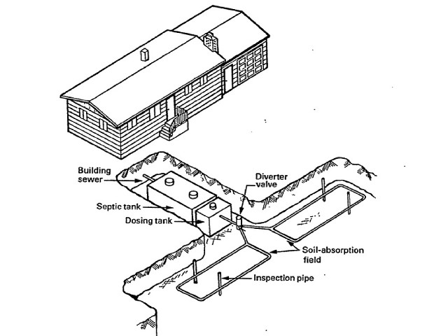
Our sketch (above left, edited by us, origianal courtesy USDA) shows a generic septic effluent dosing system, combining a septic tank, a dosing tank, a diverter valve,and two septic efflent dispersal loops through a soil absorption field.
Septic effluent is distributed to a system final treatment and disposal using either gravity methods (which depend on terrain slope -
see GRAVITY/SIPHON DOSING SYSTEMS)
or pressure methods - PRESSURE DOSING SYSTEMS (which use a pump to move effluent to its destination treatment and disposal area).
Effluent from the septic tank may be distributed for final soil absorption by several methods listed here:
- Single Effluent Line:
A 4" perforated PVC pipe receives effluent by gravity from the septic tank. The pipe is buried in a gravel trench and may be run in a straight line or a loop. - Distibution Box/Network of Lines:
A distribution box receives effluent by gravity from the septic tank and routes it to a network of perforated pipes. The network is made of multiple independent trenches which maybe on a flat or sloped site. - Serial relief line:
multiple, serially connected trenches are built on a sloping site and used serially. - Drop box:
multiple independent trenches are built on a sloping site, connected from drop boxes.
Methods For Controlling Septic Effluent Distribution Using Pressure Dosing Systems
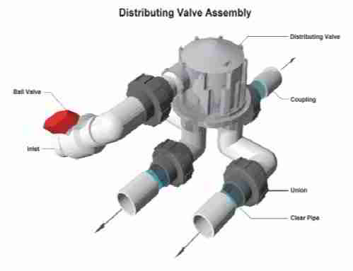
The Pressure Dosing Controls Shown Below include a Pressure Dosing distribution manifold (below left) and a pressure dosing distributing control valve. Images courtesy Washington State DEHS.
Each septic effluent dosing system has its particular operating characteristics, so one type may be more suitable than others to a particular site. These types of pressure dosing septic systems are discussed here:
- Pressure Dosing Methods
permit effluent to be dispersed over the entire absorption field more uniformly than with gravity dosing systems, making maximum use of the absorption system capacity and avoiding the problem of local area or point overloading in the absorption field. - Pressure manifold:
multiple independent trenches on sloped sites or multiple independent trenches receive effluent from a larger manifold pipe which is fed by an effluent pump from a pumping chamber. - Rigid Pipe Pressure Network:
multiple independent trenches at the same elevation receive effluent from an effluent pump and pumping chamber. - Dripline Pressure Dosing Network:
multiple independent pressure drip trenches on flat or sloping sites receive effluent from a pump and pumping chamber at low pressure (potentially even by gravity) where effluent is fed through small pipe openings permitting it to drip at a slow, controlled rate, into the trench and soils.
Controlled vs Uncontrolled Effluent Flow Control When Septic Effluent is Moved Through a Septic System
Wastewater effluent is distributed for final treatment over time either by uncontrolled, or controlled methods.
Uncontrolled septic effluent flow
A conventional gravity septic system and drainfield is "uncontrolled". When waste enters the septic tank, it forces the same volume of effluent out of the tank and into the leach field. Some experts call this a continuous or trickling septic system. Conventional septic tank and drainfields use this approach. The timing of effluent movement or "trickle" into the absorption field is based simply on when people are using the building plumbing and thus based simply on when wastewater flows out of the building into the septic tank.
Controlled septic effluent flow:
in controlled systems effluent is sent to the final treatment and disposal system such as an absorption field under either mechanical control such as a tipping or siphon system or under pump control, such as by use of a dosing system which makes use of a gravity dosing method or a pressure dosing method such as septic effluent pressure manifold, rigid pipe distribution, or a septic effluent drip network.
In some large wastewater treatment systems with a significant if not uniformly continuous inflow, outflow of the system may be continuous in some designs.
But many system use an intermittent effluent dosing method which operates by a pump controlled perhaps by a float in an effluent receiving chamber, or by a siphoning or tipping bucket mechanical system (gravity systems).
Pressure Distribution and Pressure Dosing Septic System Design Specifications

Pressure-dosed Drainfield Septic Systems use a separate effluent pumping chamber and an effluent pump such as the system in this sketch.
The
effluent pumping station is located downstream from the septic tank and is used to move septic effluent into a
pressure-fed network of distribution pipes. In some designs the effluent is pumped to move it up to
the absorption field where it then moves by gravity. Other systems pressurize the entire piping network.
Pressure dosing is used in a variety of
disposal field designs including mounds and sand beds, and have the advantage of being able to distribute effluent
uniformly throughout the absorption system, and the disadvantage of added system cost and complexity, along with
the requirement for electricity for system operation.
An alternative but possibly less long-term reliable version of a drainfield dosing system that does not require electricity is the siphon system. The sketch shows a generic pumping station of the type used with many pressure dosing systems, source US EPA and Purdue University.
Source for the following is New York State regulations on wastewater treatment and design for individual household septic systems (Note b below) and from the U.S. EPA Wastewater Manual.
(1) These methods permit the rapid distribution of effluent
throughout
the absorption system followed by a rest period during which no effluent
enters the system. The maximum length of absorption lines used in
conjunction with these methods shall be 100 feet.
(i) Pressure distribution utilizes a sewage effluent pump
to move the effluent through the pipe network and into the soil. The volume discharged in each cycle will exceed the volume available in the pipe network and will be discharged from the pipe under pressure.(ii) Dosing involves the use of a pump or siphon for pressure dosing septic systems
to move the effluent into the pipe network. Discharge from the pipe is by gravity. The volume of effluent in each dose should be 75% to 85% of the volume available in the pipe network.
(2) Dosing or pressure distribution is recommended for all septic systems
as it
promotes better treatment of wastewater and system longevity.
(3) In absorption fields, single pressure dosing units are required when
the
total trench length exceeds 500 feet. Alternate dosing units are
required when the length exceeds 1,000 feet.
(4) The use of manually operated siphons or pumps for pressure dosing septic systems is not acceptable.
(5) Pipe used in pressure dosing septic systems distribution shall
have a minimum diameter of
1.5 inches and a maximum diameter of three inches. Pipe for siphon
dosing is sized to conform with the volume of the dose and can range
from three to six inches in diameter based upon the volume of each dose.
The ends of all pipes shall be capped.
(6) Only pumps for pressure dosing septic systems
designated by the manufacturer for use as sewage effluent
pumps shall be used.
(7) Pump chambers for pressure dosing septic systems shall be equipped with an alarm
to indicate
malfunction. Siphon dosing systems normally include an overflow to the
distribution laterals. Pressure distribution systems shall not be
equipped with an overflow.
(8) Pump chambers for pressure dosing septic systems shall be sized
to provide a minimum of one day's
design flow storage above the alarm level. Siphon chambers shall have a
minimum total storage of one day's design flow below the overflow pipe.
Footnote (b):
The preceding example septic pressure dosing system design and descriptive data for septic effluent pressure distribution and pressure dosing systems is from Appendix 75-A to Public Health Law, 201(1)(1) New York State Wastewater Treatment Standards - Individual Household Septic Systems, Wastewater Treatment Design and Regulation Section, specifically
chapter 75-A.7 Distribution lines, distribution boxes, gravity flow, pressure distribution, dosing, siphons
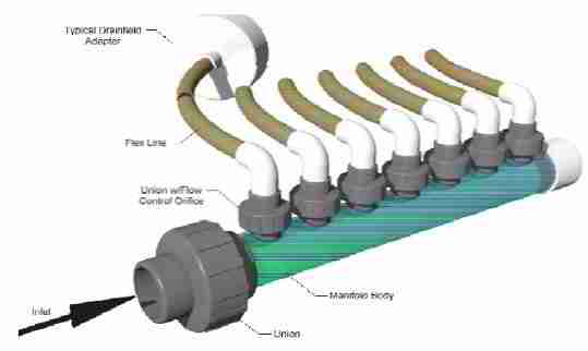
Manifold Pressure Dosing Effluent Dispersal Systems
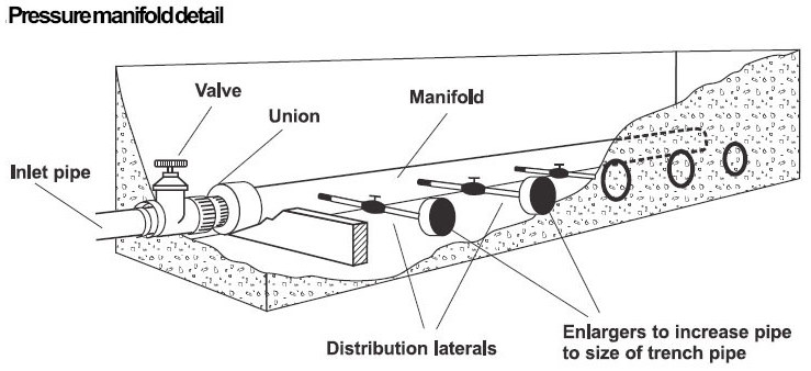
This sketch shows a closeup of the effluent distribution manifold.
The effluent pump moves effluent from the dosing chamber to this manifold under pressure. Pressurized septic effluent leaves the manifold through the small diameter black tubes or "distribution laterals".
Notice that each lateral has an individual control valve permitting the user to balance flow or even to manually alternate which distribution laterals are to be in use and which are to be left at rest.
The enlargers shown at the end of each distribution lateral permit connection of the lateral to a 4" PVC perforated pipe buried in the absorption system.
We'd infer that the effluent dispersal within the 4" pipe is by gravity not by pressure as with the next system discussed below. [Photo, U.S. EPA. Click the sketch to see a larger image of this rigid pipe pressure dosing septic effluent system example.]
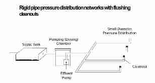
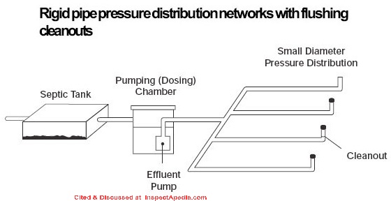
Rigid Pipe Pressure Dosing Effluent Dispersal Systems
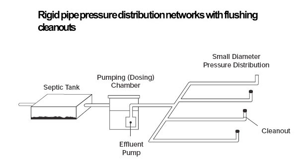
This sketch shows a septic tank, the pumping chamber,
also called a "dosing chamber" which contains the effluent pump, and the network of rigid pipe used to distribute effluent into the soil absorption system.
This design might be used with sand bed systems or mound systems as we discuss in this document. Note that the designer specified that a distribution line cleanout was to be provided at the end of each line.
This rigid pipe pressure dosing sketch appears also at the top of this page and in the EPA's Wastewater Manual. [Photo, U.S. EPA. Click the sketch to see a larger image of this rigid pipe pressure dosing septic effluent system example.]
Pressure Drip Dosing Effluent Dispersal Systems - Drip Line Septic Systems
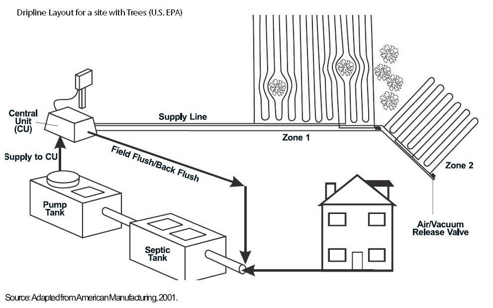
This EPA sketch shown a basic effluent drip line system layout. Effluent flows from the septic treatment tank to a pumping chamber where an effluent pump moves the effluent to a control chamber. The control chamber feeds effluent to the drip lines.
A field flush or back-flush line is connected from the control chamber back to the tank to return any settled sludge or debris to the system.
The air/vacuum release valve is installed at the very end of the drip line to assure that effluent can flow through the line to its end. [Sketch, U.S. EPA adapted from American Manufacturing - a supplier of this equipment.
See our link to our listing of product sources below. Click the image to see a larger version of this drip line septic effluent dispersal system example.]
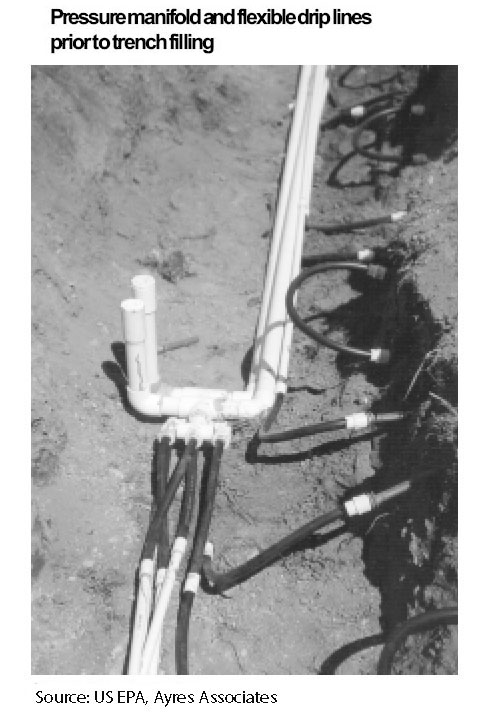
This photo shows the pressure manifold (white pipe) and flexible low pressure drip dispersal system lines (black tubing) to be used for septic effluent treatment and disposal.
As the photo caption indicates, the trench has not been filled. These components will be covered, not left exposed.
The smaller diameter black lines are the drip lines which you'll notice are buried close to the ground surface. Probably a warm climate design. [Photo, U.S. EPA, who obtained it from Ayres Associates.
Click the photo to see a larger image of this drip dispersal system example.]
...
References for Drip Dosing & Pressure Dosing Septic System Design Specifications
- Amoozegar, A.; E. W. West; K. C. Martin; and D. F. Weymann.
Dec. 11–13, 1994. “Performance Evaluation of Pressurized
Subsurface Wastewater Disposal Systems.” On-Site
Wastewater Treatment: Proceedings of the SeventhInternational Symposium on Individual and Small Community Sewage Systems. Atlanta, Georgia. - Berkowitz, S. J. . PRESSURE MANIFOLD DESIGN FOR GROUND ABSORPTION SEWAGE SYSTEMS [PDF] (1986) Originally in In: On-Site Wastewater Treatment: Proceedings of the fourth national symposium on individual and small community sewage systems. Dec. 10-11, 1984. New Orleans. American Society of Agricultural Engineers.
- Cogger, C., B. L. Carlile, D. Osborne and E. Holland. 1982. Design and installation of low-pressure pipe waste treatment systems. UNC Sea Grant College Pub. UNC-SG-82-03. 31p.
- Hoover, M. T. and A. Amoozegar. Sept. 18–19, 1989. “Performance of Alternative and Conventional Septic Tank Systems.” Proceedings of the Sixth Northwest On-Site Wastewater Treatment Short Course. University of Washington. Seattle, Washington. pp. 173–203.
- Hoover, M. T.; T. M. Disy; M. A. Pfeiffer; N. Dudley; and R. B. Mayer. 1995. On-Site System Operation and Maintenance Operators Manual. The National Environmental Training Center for Small Communities (NETCSC). West Virginia University. Morgantown, West Virginia.
- King County, WA, PRESSURE DOSING SYSTEM HOMEOWNERS MANUAL [PDF] King County/Seattle Washington, 14350 SE Eastgate Way, Bellevue WA 98007 USA, Tel: 206-477-8050, retrieved 2022/03/07 original source: https://kingcounty.gov/depts/health /environmental-health/piping/onsite-sewage-systems/maintenance/~/ media/depts/health/environmental-health/documents/oss/ OSS-homeowners-pressure-distribution-system.ashx
- Lesikar, Bruce. Agricultural Communications, The Texas A&M University System. Low-pressure dosing. Publication L-5235. 6 Sept. 1999.
- Marinshaw [excerpted by EHS, NC Public Health], "RECOMMENDED DESIGN CONSIDERATIONS FOR PREVENTING COMMON LPP PROBLEMS" [PDF], excerpted by North Carolina Health & Human Services DHHS from OSWS/DEH/NCDEHNR - 2/95, rev. 3/96; addendum to "Design of Large LowPressure Pipe Distribution Systems in North Carolina", Marinshaw, 1988
- Mitchell, D. 1983. Nonuniform distribution by septic tank systems. 1982 southeastern on-site sewage treatment conference. N. C. Div. Of Health Services, Raleigh, NC 37-45.
- New York State Department of Health, APPENDIX 75-A WASTEWATER TREATMENT STANDARDS - INDIVIDUAL HOUSEHOLD SYSTEMS , [PDF] New York State Department of Health, 3 February 2010, retrieved 3/1/2010, original source: https://www.health.ny.gov/regulations/nycrr/title_10/part_75/appendix_75-a.htm
- NSF Low-Pressure Pipe [Septic Dosing] Systems [PDF] National Small Flows Clearinghouse, Project funded by the U.S. Environmental Protection Agency under Assistance Agreement No. CX824652, retrieved 2017/04/21, original source: http://www.nesc.wvu.edu/pdf/WW/publications/eti/LPP_gen.pdf
- Ohio - DRIP DISTRIBUTION SEPTIC SYSTEM DESIGN SPECIFICATIONS [PDF] retrieved 2017/10/20, original source: http://www.odh.ohio.gov/
- Ohio DOH, Septic tank/Pretreatment to Low Pressure Pipe [PDF] Ohio State Department of Health, retrieved 2017/04/21, original source: https://www.odh.ohio.gov/~/media/ODH/ASSETS/Files/eh/STS/ho-FSlpp.ashx [does not contain design details]
- Ohio - LOW PRESSURE DISTRIBUTION SYSTEM SEPTIC DESIGN SPECIFICATIONS [PDF] retrieved 2017/10/20, original source: http://www.odh.ohio.gov/
- Ohio - LOW PRESSURE SAND FILTER SEPTIC DESIGN SPECIFICATIONS [PDF] retrieved 2017/10/20, original source: http://www.odh.ohio.gov/
- Otis, R. J. 1982. Pressure distribution design for septic tank systems. Jour. Of the Env. Eng. Div., ASCE 108(1): 123-140.
- Otis, R. J., J. C. Converse, B. L. Carlile and J. E. Witty. 1977. Effluent distribution. Home Sewage Treatment. ASAE Pub. 5-77. St. Joseph, Mich. 61-85
- Seigrist, Robert L., E. Jerry Tyler, Petter D. Jenssen, "DESIGN AND PERFORMANCE OF ONSITE WASTEWATER SOIL ABSORPTION SYSTEMS" [PDF] Extensive, detailed design guide, National Research Needs Conference Risk-Based Decision Making for Onsite Wastewater Treatment Washington University St. Louis, Missouri 19-20 May 2000, Sponsored by U.S. Environmental Protection Agency Electric Power Research Institute’s Community Environmental Center National Decentralized Water Resources Capacity Development Project
- Uebler, R. L. 1982. “Design of Low-Pressure Pipe Wastewater Treatment Systems.” 1982 Southeastern On-Site Sewage Treatment Conference Proceedings. North Carolina Division of Health Services and the Soil Science Department. North Carolina State University.
- USDA SEPTIC TANK/SOIL-ABSORPTION SYSTEMS: HOW TO OPERATE & MAINTAIN [PDF] - , Equipment Tips, U.S. Department of Agriculture, 8271 1302, 7100 Engineering, 2300 Recreation, September 1982, web search 08/28/2010, original source: http://www.fs.fed.us/t-d/pubs/pdfimage/82711302.pdf.
- U.S. Environmental Protection Agency (EPA) "DECENTRALIZED SYSTEMS
TECHNOLOGY FACT SHEET
LOW PRESSURE PIPE SYSTEMS" [PDF], EPA 832-F-99-076
September 1999, retrieved 2017/04/21, original source: https://www3.epa.gov/npdes/pubs/finallpp.pdf - U.S. Environmental Protection Agency (EPA) “Small Wastewater Systems: Alternative Systems for Small Communities and Rural Areas.” EPA Office of Water. 830/F-92/001. May 1992.
- Washington State DOH, PRESSURE DISTRIBUTION SYSTEMS, Recommended Standards and Guidance for Performance, Application, Design, and Operation & Maintenance", [PDF] Washington State Department of Health, 243 Israel Road SE, Tumwater, WA 98501 USA, Tel: (360) 236-3330 , Email: wastewatermanagement@doh.wa.gov (2012), retrieved 2017/04/21, original source: http://www.doh.wa.gov/Portals/1/Documents/Pubs/337-009.pdf DOH Publication #337-009
Reader Comments, Questions & Answers About The Article Above
Below you will find questions and answers previously posted on this page at its page bottom reader comment box.
Reader Q&A - also see RECOMMENDED ARTICLES & FAQs
On 2021-03-24 by M M - footer pipe recommendations on pressure dosing effluent system
Hi, thanks for your awesome resource it's really helped a lot while working on all the many things that have gone wrong with our lake house.....
About to start working on my (dark) Greywater pressure dosing system after leaving it over winter, and I have decided on and finished the first stage tank, second stage pumping chamber, and need to build the Drainfield. I have determined the proper size and layout, but what I cannot seem to find a good answer to, is this:
In a pressure dosed system where the pump shoots the greywater into three perforated pipes in a Gravel Based (gravel below, dirt after about 6 inches above the pipe) Mound,
Would you recommend 1st of all the "footer pipe" that some designs show, where the end of the leach field is tied together? I plan to put three in line cleanouts, so I would need wye fittings to add this, but if there is a benefit, I will.
Also, 2nd of all, Would you recommend a Vent, to introduce oxygen into the leach field and allow good movement of water? I considered drilling a hole in the top of the "footer pipe" off to the side of the main laterals (as to try to prevent water from rushing up the vent), and just running a 1" or 1 1/2" flexible black piping out of the mound and staking it in (with a mushroom / rain cap) in some nearby bushes.
I worry that maybe it will compromise the "pressure" but again im not sure.
Finally, what about the first and second stage tanks? They'll be fairly air tight, do they need vents? It would be easier to do before I landscape even though the tanks are in the ground and most of the dirt is on top.
So to make that more clear, does a pressure-dosed perforate pipe system require a footer pipe and a vent to introduce air into the drainfield and to allow good flow? What about vents for tanks? Will be building this ASAP when the ground thaws. Thank you very much,
Mike
On 2021-03-25 1- by (mod) - pressure dosing system design
@M M,
I can't provide an authoritative answer on this but I can take a stab at your questions.
In the article above we have:
(v) Maximum dimensions for pressure distribution: Using pressure distribution with a center manifold, a bed system shall have maximum dimensions of 205 feet by 20 feet.
So we see that there is an anticipation of a distribution manifold that sends effluent into the various legs - I'm not sure if your footer pipe is an addition of distribution area or something else.
I have seen people add "vent" into mounds and drainfields but in my OPINION they do little to provide oxygen to the volume of soil that actually receives the effluent. More important is the depth of the distribution piping: deeper means less oxygen - and of course important to field life is the clarity of the effluent being delivered.
You need to review pumping chamber design with your septic engineer; in general, if a tank is small and air-tight, the effluent dosing pump could run into vacuum problems that a vent would alleviate.
If you don't have a septic engineer on board I recommend hiring one; I'm doubtful that in most communities the local approving authorities will approve a DIY pressure dosing septic system plan that hasn't benefited from soil testing, site characteristics mapping, and an expert's sign-off.Just to clarify in case it's helpful:
a pressure dosing system - is a design that takes care to send effluent to the fields only at intervals rather than continuously as wastewater enters the septic tank
a pumping system - is a design that uses a separate pumping chamber to send clarified effluent to the drainfield not based on a timer (pressure dosing) but rather simply as usage fills the pumping chamber to a sufficient level;
Either of these can pump UP to a location such as a raised-bed septic or mound system which is what we see installed when the soil perc rate is poor.
You can find those designs in the ARTICLE INDEXOn 2021-03-25 by M M
Yes I am doing this DIY with family, what an ordeal. We did some informal soil perc testing and a few deep dig in channels before we started (partially just to find the lines, but it helped to examine the soil). I hadn't considered the implications of going with a pressure dosing system instead of gravity in that the county might require a sign off from an engineer.
The reason I went with a pump is because the old, failed leach field is in the only good spot for gravity.
The footer pipe, is something I saw in various diagrams online,. I assumed it was for either an extension of the leach field or for ensuring air circulation in the field. I guess since I can't put a filter in the settling tank (mostly inaccessible) I will put a tee filter in the inlet to the pump tank to clarify the effluent. Lots to think about. Thank you!
On 2021-03-02 by James Ashmore
Looking for a UNC Sea Grant College Publication UNC-SG-82-03 May 1982
Design and installation of low-pressure pipe waste treatment systems booklet.
This booklet was very useful in designing a 1" pvc low-pressure system.
On 2021-03-02 by (mod)
The Williamson County Tennesse (Williamson County 1320 West Main Street Franklin, TN 37064 Web: https://www.williamsoncounty-tn.gov/) septic department has re-published that helpful booklet. You can see their republished version as a PDF - APPENDIX 3, LOW PRESSURE PIPE SYTEMS provide by the Williamson County COUnty Document Center:
Excerpt: This Appendix shall be considered by the Department, as a comprehensive manual on the subject of Low Pressure Pipe (LPP) Systems.Additionally, this Appendix/Manual will specify how these systems are to be designed and installed in Williamson County. Important Note:
This manual was adapted from the UNC Sea Grant, College Publication UNC-SG-82-03, Design and Installation of Low Pressure Pipe Waste Treatment Systems, May 1982. The content was edited to conform to the specific geologic and physiographic characteristics of Williamson County, Tennessee.
These standards promote reliability and longevity of waste treatment systems for environmental protection and public health.
If the online original disappears, we've kept a copy on file, available on request, which we've saved offline as Low-Pressure-Septic-UNC-SG-82-03.pdf
On 2021-03-02 by Walter
Sorry, I misspoke there. Better phrasing would be to discontinue using the underground dosing pipe in the drainfield and use spray dispersal, either in the current drainfield or a new one. Thx.
On 2021-03-02 by (mod)
@Walter,
I understand the reasoning, and am guessing that your existing drainfield has failed.
Check with your local health or building department; it might be that the type of soil you have will work with aboveground spray-dispersal -or not. Without knowing soil properties area, dispersal rate, etc. we're just speculating.
Also, if you're in an area subject to freezing, any aboveground effluent dispersal method needs to be considered with care.
On 2021-03-02 2 by Walter
yes, above ground spray does work in this area. Most, if not all, newer systems are designed that way. I have been able to find some additional information and I'm now just trying to determine if another tank will be required. Thanks for the reply.
On 2021-03-02 by (mod)
@Walter,
If you have a simple, traditional 1 or 2 chamber septic tank, yes you'll probably need a separate clarified-effluent pumping chamber, supporting a pump and float controls, electrical power, and usually an above-ground control box and alarm.
On 2021-03-01 by Walter - Can a pressure dosing system be converted to use spray dispersal and thus eliminate the drain field?
Can a pressure dosing system be converted to use spray dispersal and thus eliminate the drain field?
On 2021-03-02 - by (mod) - No
@Walter, that's a pretty interesting question. I think the simple answer is probably not.
Considered that you're not eliminating the drainfield You're simply changing a method of effluent dispersal.
You still have to have an area on which it can be dispersed and the soil still needs to be able to absorb effluent.
On 2020-10-28 by john - how high should the water squirt at the end of a dosing system
how high should the water squirt at the distal end of a dosing system that requires 2.5 feet of head?
On 2020-10-28 - by (mod) -
Thanks for what sounds like an interesting plumbing exam question, John.
2.31 feet of head = 1 PSI
So your 2.5 ft. of head pressure = 1.0822 psi
So at 1 psi you won't see much squirting up, even before you've specified the pipe diameter and flow rate - two critical numbers.
On 2019-11-16 by Steve cook - allowable distance from a property line to put in a drip system
What is the allowable distance from a property line to put in a drip system
On 2019-11-16 - by (mod) -
Steve
The clearances from the edge of a drip septic system vary by country and state and by just what component of the system we're discussing - maybe as little as 5 ft - again it's not just the property line but what else is nearby. For example a well or stream could be right at the property line - that would increase the distance required .
In the ARTICLE INDEX you'll findCLEARANCE DISTANCES, SEPTIC SYSTEM
with those details.
On 2018-04-30 by Tom Amon - clay soils, pressure dosing septic system fails in wet weather
Currently living in a house on a .21 acre lot. Septic system is traditional with Half Moon pipe field (Believe it is called injector pipe). Soil is heavy clay. System was becoming sluggish so had reinstalled at cost of $3200 using maximum space available.
When heavy rains occur, system becomes sluggish still. Was wondering if a a drip or pressure dosing system installation to augment current system may be possible to solve the issue.
On 2018-04-30 - by (mod) -
Tom,
Heavy clay soil is, as you probably know, a terrible absorber of septic effluent.
Worse, if the system floods in wet weather it is simply not working - risking contaminating the local environment, nearby wells and waterways.
Dosing systems help out with limited-capacity absorption systems by a design that makes sure that the delivery of effluent to the absorption system is done at intervals - protecting the system from failure (flooding) during surges of wastewater or periods of heavy use. Obviously the septic/holding tank has to be big enough to hold the wastewater between doses.
So a pressure dosing system might help if your clay has any absorption at all.
I'd ask a local septic engineer who knows your soil conditions what she thinks.
Let us know what you're told and we might have additional suggestions or follow-up questions you could ask.
On 2018-05-01 by Tom Amon
Thank you. Now to try and find an engineer. I will let you know.
On 2018-05-01 - by (mod) -
Your BOH probably knows and has worked with local septic engineers / designers.
On 2017-04-21 1 by Charlie LePage - looking for refereces for presser dosing system sizing & trenches
Is there a good reference source for sizing the drain field & trenches using a low pressure dosing system?
On 2017-04-21 - by (mod) -
Charlie: I will add some current septic dosing system design references and your excellent question to the bottom of the article above - it may take 24 hours for the material to appear online depending on where your internet server is located.
Of these, succinct and helpful is inspectapedia.com/septic/LPP-Design-Considerations-NC-DOH-Marinshaw.pdf from Marinshaw but you'll want to see the other documents we cite and provide as PDFs too -
Take a look at that septic guide and ask again if you need more informationKeep in mind that soakbed sizing is very dependent on
- the soil percolation rate
- the volume of wastewater to be disposed-ofTypical low pressure dosing system trenches are shallow, 10-18" deep (good for assuring presence of aerobic bacteria) and about a foot to 18" in width. The length of these trenches and their number, as we noted, depend on soil percolation rate and wastewater volume to be handled.
The dosing system design, whether using a pump or other effluent dosing methods, intends to accumulate effluent until a design volume is reached, then effluent is moved to the absorption bed until the bed is fully saturated, then dosing *stops* for an interval (determined by soil properties) to permit treatment and disposal of effluent by bacterial action, soil filtration, evaporation, transpiration, as well as soil absorption.
Shallow rooted plantings can improve field transpiration.
The reserve capacity of the system holding tank has to be able to hold enough wastewater effluent to contain all the wastewater inflow between dosing periods, typically at least 24 hours of wastewater.
...
Continue reading at GRAVITY/SIPHON DOSING SYSTEMS for an alternative septic effluent dosing system, or select a topic from the closely-related articles below, or see the complete ARTICLE INDEX.
Or see these
Recommended Articles
- ALTERNATING BED SEPTIC SYSTEMS that also use a dosing system
- ALTERNATIVE DESIGN SEPTIC SYSTEM SUPPLIERS
- ATU SEPTIC SYSTEM SUPPLIERS
- DOSING CONTROL for SEPTIC MEDIA SYSTEMS - septic dosing system
- GRAVITY/SIPHON DOSING SYSTEMS - septic dosing systems that do not use pressure nor drip distribution
- PRESSURE DOSING SEPTIC SYSTEMS - septic dosing systems using pressure
- RAISED BED SEPTIC SYSTEMS - may use a dosing system
- SEPTIC SYSTEM DESIGN ALTERNATIVES - home
- SEPTIC SYSTEM DESIGN BASICS - home
- TYPES OF SEPTIC SYSTEMS - master list
Suggested citation for this web page
PRESSURE DOSING SEPTIC SYSTEMS at InspectApedia.com - online encyclopedia of building & environmental inspection, testing, diagnosis, repair, & problem prevention advice.
Or see this
INDEX to RELATED ARTICLES: ARTICLE INDEX to SEPTIC SYSTEMS
Or use the SEARCH BOX found below to Ask a Question or Search InspectApedia
Ask a Question or Search InspectApedia
Try the search box just below, or if you prefer, post a question or comment in the Comments box below and we will respond promptly.
Search the InspectApedia website
Note: appearance of your Comment below may be delayed: if your comment contains an image, photograph, web link, or text that looks to the software as if it might be a web link, your posting will appear after it has been approved by a moderator. Apologies for the delay.
Only one image can be added per comment but you can post as many comments, and therefore images, as you like.
You will not receive a notification when a response to your question has been posted.
Please bookmark this page to make it easy for you to check back for our response.
Our Comment Box is provided by Countable Web Productions countable.ca
Citations & References
In addition to any citations in the article above, a full list is available on request.
- In addition to citations & references found in this article, see the research citations given at the end of the related articles found at our suggested
CONTINUE READING or RECOMMENDED ARTICLES.
- Carson, Dunlop & Associates Ltd., 120 Carlton Street Suite 407, Toronto ON M5A 4K2. Tel: (416) 964-9415 1-800-268-7070 Email: info@carsondunlop.com. Alan Carson is a past president of ASHI, the American Society of Home Inspectors.
Thanks to Alan Carson and Bob Dunlop, for permission for InspectAPedia to use text excerpts from The HOME REFERENCE BOOK - the Encyclopedia of Homes and to use illustrations from The ILLUSTRATED HOME .
Carson Dunlop Associates provides extensive home inspection education and report writing material. In gratitude we provide links to tsome Carson Dunlop Associates products and services.
 | HOME | ABOUT | ASK a QUESTION | CONTACT | CONTENT USE POLICY | DESCRIPTION | POLICIES | PRIVACY | |
| © 2024 - 1985 Publisher InspectApedia.com - Daniel Friedman | |||||||||