
InspectAPedia® FREE Encyclopedia of Building & Environmental Construction, Diagnosis, Maintenance & Repair |
Question? Just ask us! InspectAPedia
|
 Septic Drainfield Design
Septic Size Requirements Guide

- POST a QUESTION or COMMENT about septic drainfield or soakaway bed size or capacity requirements & design
This article and its tables explain how to determine the size and design of a septic leachfield or soakaway bed or drainfield. We discuss rules of thumb used to set the size of a conventional septic drainfield.
We discuss septic drainfield trench lengths for various soil perc rates and wastewater flows.
Septic drainfields, also called leach fields, absorption beds, soil absorption systems, soakaway beds, and leaching beds, perform the functions of septic effluent treatment and disposal in onsite wastewater treatment systems, conventionally called "septic systems".
InspectAPedia tolerates no conflicts of interest. We have no relationship with advertisers, products, or services discussed at this website.
How large does the septic drainfield need to be?
 The types of septic absorption field designs explained below are:
- Conventional Septic Leach Fields
- Deep Septic Absorption Trench Systems
- Shallow Trench Systems
- Cut and Fill Septic Systems
- Absorption Bed Systems
- Gravelless Septic Absorption Systems
- Seepage Pits
A conventional septic tank performs roughly 45% of the sewage treatment or less at a private home served by a septic system.
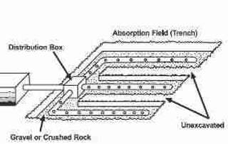
[Click to enlarge any image] Sketch - USDA.
The rest of the wastewater treatment and ultimately the liquid disposal occurs in the drainfield.
As you will read below, there is no one "right" septic absorption field size. Rather, the size needed (in square feet of area, presumably also unencumbered by trees, driveways, buildings, etc.) depends on several variables such as the rate at which the soil can accept liquid (the percolation or "perc" rate), and the expected daily volume of wastewater.
A lot with a good percolation rate or "perc" of perhaps one inch of percolation in 1-5 minutes might require about 125 feet of drainfield trench for a typical two bedroom home. If the same home were built where there was a poor soil percolation rate of 46-60 minutes per inch, 333 linear feet or more might be required for the absorption area. (See our drainfield sizing TABLE 4A below).
Typically, septic leach fields (synonyms: drainfield, leach bed, soakaway bed, absorption bed) are built by placing perforated effluent distribution pipes in a field or bed of gravel.
There are several types of absorption systems however, each having different effluent disposal capacity.
The leach field is a series of trenches that may be up to 100-feet long and 1 foot to 3 feet in width, separated by six feet or more, depending on local requirements, and sometimes constructed leaving space between the original lines to install replacement leach lines when needed. - paraphrasing USDA.
Drainfield size and location also have to take into account local zoning - setback requirements from property borders, setbacks from streams, wetlands, wells, water supply lines, and other encumbrances.
Article Contents
- SEPTIC TRENCH LINE SPECIFICATIONS
- SEPTIC SOAKBED DETAILS
- LEACH FIELDS
- GRAVELLESS SEPTIC SYSTEMS
- DEEP TRENCH SEPTIC SYSTEMS
- SHALLOW TRENCH SEPTIC SYSTEMS
- CUT & FILL SEPTIC SYSTEMS
- ABSORPTION BED SEPTIC SYSTEMS
- SEPTIC DRAINFIELD PIPE DIAMETER vs FLOW
- SEPTIC DRAINFIELD SIZE CODES / REFERENCES
Septic Drainfield Design Basics: septic trench line specifications
 Below we summarize the basics of septic drainfield design, followed by more detailed septic field design specifications for common types of drainfields or soakaway beds.
In the most common design of drainfield, perforated pipes are buried in gravel-filled trenches to form the drainfield.
[Click to enlarge any image]
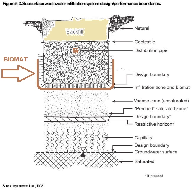
This sketch shows a cross section of a typical drainfield trench, and places below the trench the critical biomat as well as other septic field design areas and considerations. (Source US EPA who in turn obtained the drawing from Ayres Associates)
Where lot space does not permit drainfield trenches such as I've just described, a septic engineer may specify that seepage pits
or galleys are to be installed. These fit in a smaller space since a single pit may be 6' to 8' in diameter.
But the depth to which effluent is
being delivered (4' or more) means that the sewage effluent is unlikely to be fully treated by a biomass. These systems may successfully "dispose" of
effluent but they are probably not adequately "treating" it.
The Biomat: The formation, clogging, and measures to protect and extend the life of the biomat, or organism layer below and around soil absorption system effluent discharge piping is discussed
at BIOMAT FORMATION & SEPTIC LIFE as a subchapter of this text.
- Perforated septic drainfield pipes are
placed in gravel-filled trenches
across the slope line of sloped property (so that all of the effluent doesn't simply rush down to and leak out at the end of the drain line pipe). - Drainfield trench piping slope specifications:
While some experts describe the bottom of these trenches as "level" in practice they are dug to slope slightly, perhaps 1/8" per foot or less.
- Septic drainfield pipe hole or perforation position: up or down?
As you see in the sketches shown here, the septic leaching bed perforated pipe is placed on a bed of gravel and then covered with more gravel. Do not place the pipe at the bottom of the trench before any gravel is placed therein.
We like to place the pipe with perforations at the 5 o'clock and 7 o'clock positions so that we're not simply storing and collecting sludge and effluent in the pipe bottom;
By not placing the perforated septic drainfield pipe with one of its rows of holes facing directly down (at 6 o'clock position) we defer the clogging of the pipe effluent drain openings.
More about "holes up" or "holes down" on footing drains, a different situation, is
at FOOTING DRAINS HOLES DOWN.

Our second drainfield sketch (left, USDA) shows a slightly different view, in this case an isometric cross-section drawing of a septic drainfield trench.
- Septic drainfield trench depth specification:
A typical septic drainfield trench is 18 to 30 inches in depth, with a maximum soil cover over the disposal field of 36"; or per the USDA, 2 feet to 5 feet in depth.
AtReferences or Citations we cite these sources.
In some climates such as northern Minnesota we have observed drainfield trenches placed much deeper - unfortunately meaning that while effluent disposal may be protected from freezing, effluent treatment may be marginal. - Septic drainfield trench width specifications:
Typically septic trenches are 8 to 12 inches wide in some applications, or 18" to a maximum of 36" wide in traditional, conventional septic drainfield designs.
Regardless of actual drainfield trench width, for design purposes each linear foot of drainfield line is considered to provide one square foot of drainage area (by many building code or health department septic design approving authorities). - Septic drainfield trench spacing:
The trenches are dug about 6 feet apart on center (center of pipe to center of next pipe) which allows, in good design, space for a set of replacement trenches to be placed between the original ones when the first set fails. - Septic drainfield trench length:
The maximum length of a trench is typically about 150 feet but we have found installations that were three times that length.
Some writers opine that the maximum septic trench line is 100 feet. A realistic answer is, it depends - on site and soil conditions. - Septic drainfield pipe diameters:
The usual minimum septic drainfield pipe inside diameter is 4" - Septic drainfield gravel (aggregate) specification:
Typically, washed gravel, 3/4" to 2 1/2" (pretty big) gravel is placed for a depth of 12" under the drain line piping ("septic drain tile" in some references).
The pipe is then covered by additional gravel to a depth of at least 2" over the top of the septic drain line before backfill is added.
Required by septic codes in some jurisdictions, and optionally in others, septic installers place a geotextile over or around the gravel and pipe to reduce clogging by dirt infiltration from the septic trench backfill. - Septic drainfield pipe or drain tile connections:
Modern drainfields constructed using perforated plastic pipe are comprised of pipe sections that are physically connected together: one end of each pipe is expanded to slip over the diameter of its mating section.
Older traditional drainfields made of other perforated piping were constructed by laying perforated pipe end to end, with abutting pipe ends spaced 1/4" apart and protected from backfill soil by a layer of roofing felt.
Summary Table of Typical Disposal Field Specifications |
|
| Drainfield / Soakbed / Seepage Bed Component | Specification |
| Absorption trench (leach line) | |
Maximum Length |
100 Feet |
Maximum earth cover fill thickness (depth) over Trench Top |
36 inches |
| Maximum slope of trench (grade) | 4 inches / 100 feet |
| Minimum slope of trench (grade) | level |
Minimum bottom width of trench |
18 inches |
Minimum spacing between lines, edge to edge |
8 feet |
Minimum usable absorptive material below trench bottom |
12 inches |
Minimum filter material over drain pipes or lines |
12 inches |
Maximum distance from drain line to trench edges |
18 inches |
Notes to the Table Above
Table sources include the Shasta County Department of Environmental Health, Shasta County, CA.
Other Leachfield Construction Specifications
- Base material under & around drainfield piping: stone or equivalent aggregate:
Before drain lines are laid, crushed stone, gravel, slag, or similar filter materials clean in appearance and varying in size from three-quarter inch to two and one-half inches and otherwise acceptable to the Shasta County Director of Environmental Health shall be placed in the trench to the depth and grade required by this paragraph:
The filter material in the leaching field shall conform to the following standards:
Effective size 3/4 inch, uniformity coefficient 3.0, voids 40 percent by volume.
The filter material shall have a cleanness value of at least 70 using test 18 method No. Calif. 227-E method of test for evaluating cleanness of course aggregate.
The gravel shall be placed in the trenches in a manner which will leave the sides and bottom free from deposits of rock dust or cement dust.
"Effective size" for the purpose of these Standards is that size of grain which is larger than 10 percent of the material by weight.
The uniformity coefficient for the purpose of these Standards is that sieve that passes 60 percent of the material divided by sieve size that passes 10 percent of the material.
Drain lines shall be completely encased by filter material to prevent closure of voids with earth backfill. - Shasta County cited below - Filter material over drainfield lines before backfill
Straw, newspaper, untreated building paper or similar materials shall be placed over filter materials in leach lines or seepage pits prior to backfilling. - Shasta County DEH. - Covering over drainfields:
The site of the initial and replacement disposal fields shall not be covered by asphalt or concrete or subject to vehicular traffic or other activity which would adversely affect the soil. - op. cit.
See: - Drainfield construction in backfill:
Do not construct the drainfield in filled ground. Exceptions, see
These example specifications for a septic disposal field, also referred to as drainfield, leach field, soakbed, soak trenches etc., are based on Shasta County California's septic code cited below.
Septic Drainfield Inspection Ports
A high quality septic drainfield or leach bed design includes inspection ports or pipes that permit inspection of the condition of the field. Vertical pipes are placed, usually at the end of each drainfield trench or section or at critical or suspect areas near the drainfield, to permit monitoring of liquid levels in the drainfield trenches.
If a few ports are included outside the drainfield area they will aid distinguishing between a drainfield suffering local effluent saturation from an area groundwater problem that also impedes the drainfield operation.
Some installers trim the inspection ports to ground level, sealing each with a removable cap to permit inspection of the drainfield condition without interfering with mowing.
Detailed Specifications for Septic Absorption Field Designs
The following specifications for septic drainfields or leaching beds, of various types, designs, and depths, are adapted and expanded from: New York State Appendix 75-A.8 Subsurface treatment, of New York's Wastewater Treatment Standards for Individual Household Systems.
We also include excerpts and references from other U.S., Canadian, and other authorities at state and provincial levels, and from the US EPA Onsite Wastewater Treatment Systems Manual which is available free from the US EPA and is provided in a linked-to copy at theReferences or Citations section of this article.
General Information
All effluent from septic tanks or aerobic tanks shall be discharged to a subsurface treatment system. Surface discharge of septic tank or aerobic unit effluent shall not be approved by the Department of Health or a local health department acting as its agent.
1. Conventional Septic Leach Fields
[ED. NOTE: This section discusses the design requirements for septic absorption fields, also called leach fields, drain fields, drainfields, soakaway beds, seepage beds, or conventional soil absorption systems.]
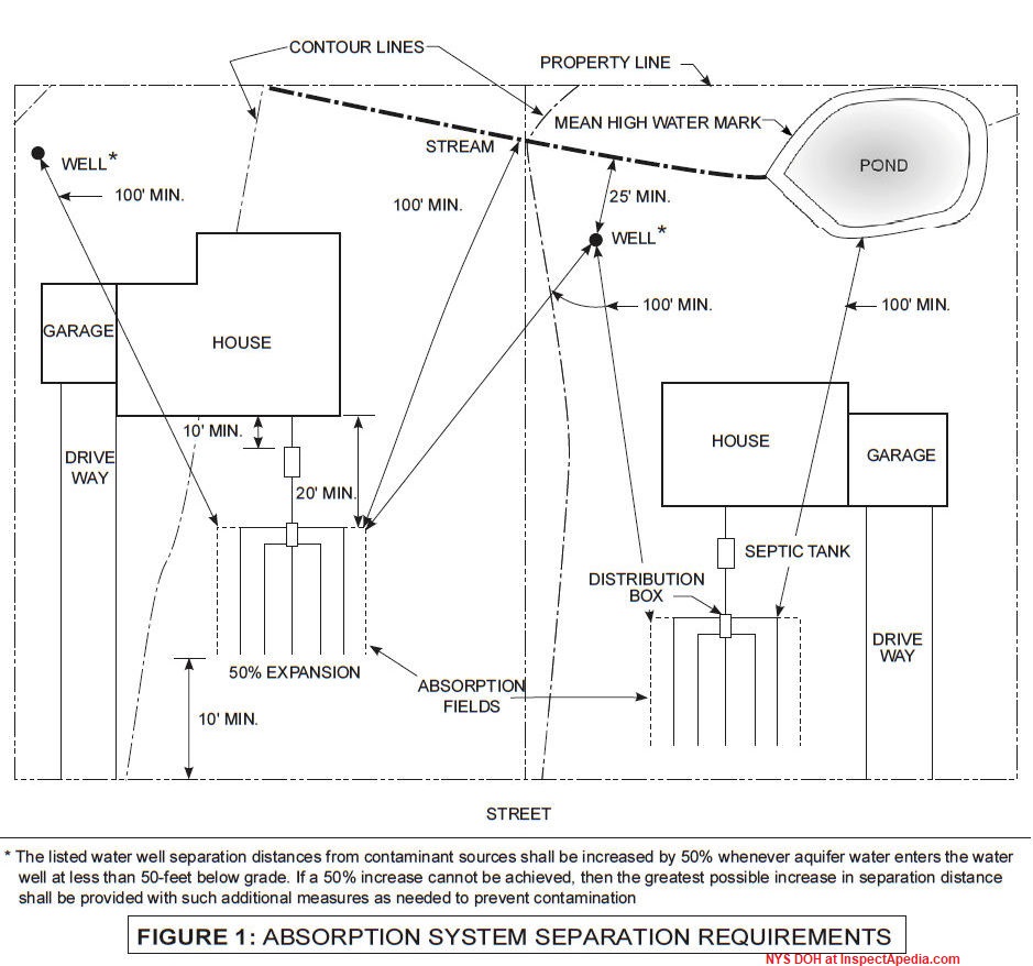
a. Site requirements for Conventional Septic Drainfields
(i) The minimum distances that absorption fields shall be separated from other facilities are shown in the sketch below.
[Click to enlarge any image]
See details and tables of septic component separation distances from various site features found
at CLEARANCE DISTANCES, SEPTIC SYSTEM
(ii) A minimum of four feet of usable soil shall exist above bedrock and groundwater with a minimum separation of two feet to the lowest part of any trench.
(iii) Absorption fields shall not be built under driveways, parts of buildings or under above-ground swimming pools or other areas subject to heavy loading. Surface waters shall be diverted from the vicinity of the system.
b. Design criteria for Conventional Septic Drainfields
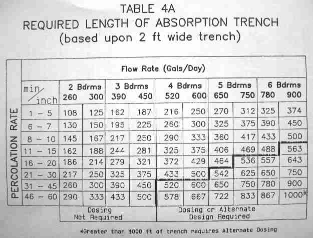
(i) The required length of absorption trench is determined from Table 4A based upon the percolation test results and confirmed by the soil evaluation. The maximum trench width for design purposes shall be 24 inches. Only 24 inches shall be allowed for absorption area calculations. W
here trenches exceed 24 inches in width, calculations of absorptive area shall be based on a width of 24 inches.
(ii) Adjacent trenches shall be separated by at least four feet of undisturbed soil. Individual trenches shall be constructed parallel to the ground contours with trench bottoms as near level as possible. They need not be perfectly straight but abrupt changes in direction shall be avoided.
Table 4A of Septic Drainfield Trench Lengths Determined by Soil Percolation Rate and Daily Wastewater Input Flow
P
|
Table 4A - Septic Wastewater Effluent Input Flow Rate (Gallons per Day) [1] |
||||||||||
| Minutes / Inch |
2 Bdrms |
3 Bdrms |
4 Bdrms |
5 Bdrms |
6 Bdrms |
||||||
| 260 gpd |
300 gpd |
390 gpd |
450 gpd |
520 gpd |
600 gpd |
650 gpd |
750 gpd |
780 gpd |
900 gpd |
||
Required number of feet of absorption trench, assuming a 2-ft wide conventional gravel trench |
|||||||||||
| 1 - 5 | 108 ft. | 125 ft. | 162 ft. | 187 ft. | 216 ft. | 250 ft. | 270 ft. | 312 ft. | 325 ft. | 374 ft. | |
| 6 - 7 | 130 | 150 | 195 | 225 | 260 | 300 | 325 | 375 | 390 | 450 | |
| 8 - 10 | 145 | 167 | 217 | 250 | 290 | 333 | 360 | 417 | 433 | 500 | |
| 11 - 15 | 162 | 188 | 244 | 281 | 325 | 375 | 406 | 469 | 488 | 563 | |
| 16 - 20 | 186 | 214 | 279 | 321 | 372 | 429 | 464 | 536 | 557 | 643 | |
| 21 - 30 | 217 | 250 | 325 | 375 | 433 | 500 | 542 | 625 | 650 | 750 | |
| 31 - 45 | 260 | 300 | 390 | 450 | 520 | 600 | 650 | 750 | 780 | 900 | |
| 46 - 60 | 290 | 333 | 433 | 500 | 578 | 667 | 722 | 833 | 867 | 1000[2] | |
| Dosing not required (but recommended) |
Dosing system or alternative design is required | ||||||||||
Notes to the Septic Drainfield Trench Length Table Above
[1] Original source: New York State NYS75-A.8 Table 4A [image file]
[2] Conditions that require more than 1000 feet of septic drainfield trench must have an alternative dosing system design.
An Alternate Table for Determining Septic Drainfield Size
The following is adapted from our engineer's article summarizing "How Big Should the Septic Leach Field Be" found at
HOW BIG SHOULD THE LEACH FIELD BE?
Determining the required size of a leach field is a bit more complicated. The first thing to consider is the nature of the soil in which the leach field is to be constructed. Because water has to be absorbed in the soil, we need to know how fast it can be absorbed.
This is called the percolation rate and is expressed as the time it takes for water in a test hole to decrease in level by one inch (minutes/inch).
We must also know the type of soil and whether seasonal changes in the natural level of groundwater will interfere with the satisfactory operation of the system. Seasonal groundwater must be more than four feet from the bottom of the leach field trenches.
Judgments regarding the soil conditions and percolation rates are best left to a professional. If the soil percolates very quickly, (less than one minute per inch) or very slowly (greater than 60 minutes per inch) it will not be possible to install a standard leach field in the existing soil.
We must now determine the amount of water that has to be absorbed each day. As with the septic tank sizing, there are also "rules of thumb" that can be used to find out how much water must be absorbed each day for each bedroom in the house (expressed as gallons per day per bedroom).
- For older houses
(built before 1979)
we must allow 150 gallons per day (gpd) per bedroom. - Homes with 3.5 gpf toilets:
For houses where the toilets are limited to no more than 3.5 gallons per flush and the faucets and showerheads are limited to 3 gallons per minute or less, we must allow 130 gpd per bedroom. - Homes with 1 gpf toilets:
For houses with water-saving toilets that use only one gallon per flush we allow 90 gpd per bedroom.
The required flow rate is found by multiplying the appropriate flow by the number of bedrooms (in this case, we do not have to count a garbage disposal as a bedroom).
Knowing the rate at which water can be absorbed by the soil (the percolation rate) and the flow rate (in gallons per day), we can use the following table to calculate how many square feet of absorption field is needed.
Readers will notice that this table is similar to but less detailed than our typical state or board of health table above at TABLE 4A.
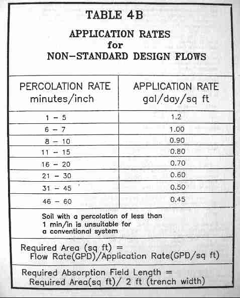
This table specifies the allowable wastewater application rate into the soil of a conventional septic system drainfield as a function of the soil percolation rate for percolation rates between 1 minute per inch to 60 minutes per inch.
Table 4B - Septic Drainfield Soil Application Rates for Non-Standard Wastewater Flow Quantities
This table specifies the allowable wastewater application rate into the soil of a conventional septic system drainfield as a function of the soil percolation rate for percolation rates between 1 minute per inch to 60 minutes per inch.
In other words, the table shows the allowable volume of wastewater in gallons that can be applied per day per square foot of septic field size.
Soils with a percolation rate of less than 1 minute per inch should not be used for a conventional septic drainfield.
Readers will note that this table considers only the dimensions of the bottom of the drainfield trench in considering the effective soil absorption area.
Typically a conventional drainfield trench is 2 ft. wide, so the effective absorption area is simply 2 ft. x field-length in ft.
Beware that in some jurisdictions, when calculating required drainfield trench lengths the authorities may consider the trench width to be a nominal one-foot wide regardless of its actual width.
Table 4B - Required Size Septic Leach Field for Non-Standard Flows |
|
| Absorption Percolation Minutes per Inch |
Allowable Application Rate - Gallons per Day per Square Foot |
| > 1 | Not Acceptable |
| 1 - 5 | 1.2 |
| 6 - 7 | 1.0 |
| 8 - 10 | 0.9 |
| 11 - 15 | 0.8 |
| 16 - 20 | 0.7 |
| 21 - 30 | 0.6 |
| 31 - 45 | 0.5 |
| 46 - 60 | 0.45 |
Notes to the table just above
Original source: New York State Septic Design Code TABLE 4B - APPLICATION RATES [Image File]
- Soil with a percolation rate of less than 1 minute /inch or more than 60 minutes/inch is un-suitable for a conventional septic system design: the wastewater will be absorbed into surrounding soil too rapidly to permit adequate treatment.
- Required Septic Absorption Field Area = Flow Rate (GPD) / Application Rate (GPD / Sq. Ft.)
- Required Septic Absorption Field Length = Required Area (Sq. Ft.) / 2 ft (assumed trench width)
- Note that this table considers only the dimensions of the bottom of the drainfield trench in considering the effective soil absorption area. Typically a conventional drainfield trench is 2 ft. wide, so the effective absorption area is simply 2 ft. x field-length in ft.
- Note that some jurisdictions may set a maximum length of 100 ft. (or another figure) for absorption field trench length.
- Beware that in some jurisdictions, when calculating required drainfield trench lengths the authorities may consider the trench width to be a nominal one-foot wide regardless of its actual width.
c. Materials used for Conventional Septic Drainfields
(i) Perforated distributor pipe shall be used in the trenches.
(ii) Solid (non-perforated) pipe shall be used between the distribution box and the trenches.
(iii) Perforated pipe shall be made of rigid or corrugated plastic and be labeled as fully meeting ASTM standards for use in septic
systems.
(iv) Corrugated plastic pipe delivered in coils is not to be used unless provision is made to prevent the recoiling or movement of the
pipe after installation.
(v) Aggregate shall mean washed gravel or crushed stone 3/4 - 1 1/2 inches in diameter. Larger diameter material or finer substances and run-of-bank gravel are unacceptable.
(vi) The aggregate shall be covered with a material that prevents soil from entering the aggregate after backfilling, yet must permit air and moisture to pass through.
(vii) The preferred material for covering the aggregate is a permeable geotextile. Untreated building paper or a four inch layer of hay or straw is acceptable. Polyethylene and treated building paper are relatively impervious and shall not be used.
d. Construction of Conventional Septic Drainfields
(i) Septic drain field trench locations and depths
should be marked by stakes before the trenches are excavated. The natural surface shall not be significantly
disturbed.
If
the site is re-graded or similarly disturbed, the soil shall be allowed to stabilize and new percolation tests conducted.
(ii) Septic drainfield trench depth shall be as shallow as possible,
but not less than 18 inches. At least six inches of aggregate is placed below the
distribution line and two inches above the line. The earth cover over the aggregate should not exceed 12 inches in order to enhance natural
aeration and nitrogen uptake by plant life.
(iii) Septic drainfield or soakaway trenches shall be excavated
to design depth with bottoms practically level.
(iv) Heavy equipment
shall be kept away from the field because the weight may permanently alter
soil characteristics due to compaction, cause trench cave-ins, and/or mis-align and break pipe.
(v) Septic drainfield or soakbed trench bottoms
are to be raked and immediately covered with at least six inches of aggregate.
(vi) Septic drainfield / leachfield trench walls:
Any smeared surfaces on the trench walls are to be raked.
(vii) Septic drainfield effluent distribution lines
are carefully placed on the aggregate and covered with
aggregate to a depth of at least two inches over the top of the pipe. Additional aggregate may be required to bring the top of the aggregate
to within six to 12 inches of the surface.
(viii) In gravity distribution septic systems, the pipe shall be carefully sloped
at between 1/16 inch and 1/32 inch per foot. Grades shall be determined
by an engineer's level, transit or carpenter's level.
(ix) Septic drainfield / soakbed trench cover:
After the upper aggregate is placed, the geotextile, untreated building paper, hay or straw is to be immediately installed and the
trench backfilled with native soil.
If the drainfield trenches cannot be immediately backfilled, they should be temporarily covered with an
impervious material such as treated building paper to prevent sidewall collapse and siltation into the aggregate.
(x) Septic drainfield / soakaway trench backfill:
The earth backfill is to be mounded slightly above the original ground level to allow for settling and after settlement the entire area
should be graded without the use of heavy equipment and seeded with grass.
[See our warnings at CONSTRUCTION OF SHALLOW SEPTIC SYSTEM ABSORPTION TRENCHES]
2. Deep Septic Absorption Trench Systems
a. Site Requirements for deep trench septic systems
These are used on sites where a usable layer of soil is overlaid by three to five feet of impermeable soil.
b. Design Criteria for deep trench septic systems
(i) There shall be at least four feet of usable soil beneath the impermeable layer.
(ii) The required length of absorption trench is determined from Table 4A (above on this page) based upon percolation tests conducted in the underlying soil.
c. Materials used for Deep Septic Absorption Trench Systems
Deep trench septic systems use essentially the same materials as found at
CONVENTIONAL SEPTIC LEACH FIELDS
d. Construction specifications for deep trench septic absorption systems
(i) Septic drainfield / soakbed trenches are excavated at least two feet into the usable layer
and backfilled with aggregate or coarse sandy material
containing a low percentage of fines (very small soil particles) more permeable than the underlying material to a level 30 inches below the original ground surface.
(ii) An absorption trench system as described in
CONVENTIONAL SEPTIC LEACH FIELDS is constructed in the upper 30 inches of the excavation.
3. Shallow Trench Septic Systems
a. Site Requirements for shallow septic system absorption trenches
These systems are used where there is at least two feet but less than four feet of usable soil and/or separation to boundary conditions.
b. Design criteria for shallow septic absorption trenches
(i) A minimum two foot separation must be maintained between the bottom of each septic soakbed / drainfield trench and all boundary conditions.
(ii) The bottom of each septic drainfield trench trench must not be above the original ground surface.
(iii) Septic trench fill material:
Material of the same permeability as the underlying original soil shall be used as fill material. The depth of the fill shall not be
greater than 30 inches above the original ground elevation.
(iv) An absorption trench system as described in CONVENTIONAL SEPTIC LEACHFIELDS is designed using the percolation of the underlying original soil.
c. Materials used for Deep Septic Absorption Trench Systems
Shallow trench septic systems use essentially the same materials as found
at CONVENTIONAL SEPTIC LEACH FIELDS
d. Construction of Shallow Septic System Absorption Trenches
(i) Heavy equipment shall be kept out of the absorption area.
(ii) Fill material is carefully placed within the absorption area.
(iii) The edge of the fill material shall be tapered at a slope of no greater than one vertical to three horizontal.
On sloped sites a
diversion ditch shall be placed on the uphill side to prevent runoff from entering the fill.
(iv) The absorption trench system is constructed in the fill material, extending into the existing natural soil.
4. Cut and Fill Septic Systems
A cut and fill septic system is an absorption trench system installed on sites where impermeable soil overlays a permeable soil.
a. Site Requirements for cut and fill septic systems
Cut and fill septic systems may be used where all the following conditions are found:
(i) A soil with a percolation rate slower than 60 minutes per inch, such as clay or clay loam, overlays a usable soil with a percolation rate faster than 60 minutes per inch;
(ii) At least three feet of usable soil is available beneath the tight soil;
(iii) All minimum vertical and horizontal separation distances can be maintained as described
at CLEARANCE DISTANCES, SEPTIC SYSTEM.
b. Design criteria for cut and fill septic systems
(i) It shall provide for the removal of the overlaying unusable soil and replacement by soil having a percolation rate comparable with the underlying soil.
(ii) An absorption trench system is designed as described
in CONVENTIONAL SEPTIC LEACHFIELDS.
(iii) The required length of septic effluent absorption trench is based upon the percolation of the underlying soil or the fill material, whichever has the slower percolation (lower permeability).
c. Materials used for Cut and Fill Absorption Trench Systems
Cut and fill trench septic systems use essentially the same materials as found
at CONVENTIONAL SEPTIC LEACH FIELDS
d. Construction of cut and fill septic systems
(i) The cut and fill septic system trench area excavated and filled must provide at least a five foot buffer in each direction beyond the trenches.
(ii) The material placed above the cut and fill septic trenches shall have a percolation rate faster than 60 minutes per inch.
(iii) Original surface material shall not be used as backfill above the cut and fill septic system trenches.
(iv) The surface area of the cut and fill septic system must be mounded and graded to enhance the runoff of rainwater from the system and seeded to grass.
5. Absorption Bed Septic Systems
An absorption bed system operates on a principal similar to the absorption trench except that several laterals, rather than just one, are installed in a single excavation. T
his reduces the effective sidewall infiltration area per linear foot of lateral or leach line.
a. Site Requirements for absorption bed septic system
(i) Percolation rate limits for absorption bed septic systems:
A bed system may be built in soils with a percolation rate between one and 30 minutes per inch.
A n absorption bed septic system shall not
be built where the soil evaluation indicates silty loam, clay loam, or clay.
(ii) Slope of the site of an absorption bed septic system shall not exceed eight percent.
(iii) Absoption bed septic systenm site shape:
Septic absorption bed systems are more practical on sites that are long and narrow with a minimal slope.
(iv) All absorption bed septic vertical and horizontal separation distance requirements shall be met.
b. Design Criteria for absorption bed septic systems
(i) Pressure distribution is required for the installation of an absorption bed system.
The local health department having jurisdiction
may allow the use of siphon dosing on specific sites.
(ii) The maximum width of the bed of an absorption bed septic design shall be 20 feet.
The maximum length of each lateral from a pressure manifold shall be 100 feet.
Utilizing a
center manifold system, a bed may then have a maximum length of 200 feet.
Laterals for siphon dosing systems in beds are limited to 75 feet.
(iii) The depth of the septic effluent absorption bed shall be between 18 and 30 inches below original ground level.
(iv) Absorption bed septic system laterals shall be spaced five (5) feet apart.
Two and one-half feet (2 1/2') must be provided between the laterals and the sidewalls. In the maximum width of 20 feet, only four laterals may be installed.
(v) Maximum dimensions for absorption bed septic effouent pressure distribution:
Using pressure distribution with a center manifold, a bed system shall have maximum dimensions of 205 feet by 20 feet.
(vi) The required septic effluent absorption bed bottom area shall be calculated from the application rates shown in Table 5 - below
Table 5 - Absorption Bed Septic System Required Bottom Area
Table 5 - Absorption Bed Septic Bottom Area Size Required |
|
| Percolation Rate Min / Inch |
Application Rate Gal / Day / Sq.Ft. |
| 1 - 5 | 0.95 |
| 6 - 7 | 0.80 |
| 8 - 10 | 0.70 |
| 11 - 15 | 0.60 |
| 16 - 20 | 0.55 |
| 21 - 30 | 0.45 |
| >30+ | Not Acceptable |
Notes to the table above
Adapted from this original source: NYS Septic Design Code, Table 5, Absorption Bed Septic Systems -- Required Bottom Area
c. Materials used for Absorption Bed Systems
Absorption bed septic systems use essentially the same materials as found
at CONVENTIONAL SEPTIC LEACH FIELDS
d. Construction of absorption bed septic systems
(i) Heavy construction equipment shall be kept outside the proposed
bottom area of the bed.
Watch out: See warnings
at SHALLOW BED SEPTIC ABSORPTION TRENCH CONSTRUCTION
(ii) The required bed bottom area is excavated as level as practical.
(iii) The bottom and sides of the excavation are hand raked to reduce soil smearing.
(iv) After excavation, a six inch layer of aggregate is placed across the bottom of the bed.
(v) The laterals are laid level on the aggregate and covered with aggregate to a level two inches above the top of the pipe.
(vi) The entire bed area is covered with a permeable geotextile. Untreated building paper or a four inch layer of loose hay or straw may be substituted if a permeable geotextile is unavailable.
6. Gravelless Septic Absorption Systems
Because they omit gravel, the soakaway bed or drainfield trench dimensions for no-rock or gravelless septic systems are different than for conventional drainfields.
This topic has moved to a separate article now found
7. Seepage Pits for septic system effluent disposal
If you scrolled down in this document to look for information on Seepage Pit construction, that subchapter discussing the design and use of seepage pits for onsite wastewater disposal is published as a separate web page
See SEEPAGE PITS.
Septic Drainfield Pipe Sizing
 What is the effect of septic effluent disposal piping diameter on the cost and size of a septic drainfield?
OPINION: You might need additional linear feet of septic drainfield trench when using smaller effluent dispersal piping. If so that will increase the cost of the drainfield much more than the savings from using a smaller diameter pipe.
Also the smaller diameter pipe may be more-prone to clogging failures.
On 2021-08-12 by inspectapedia.com.moderator (mod) - ok to use 3" perforated pipe in a septic drainfield?
@Anonymous,
You could 3-inch triple-perforated drainfield trench pipe but (though I'm no septic engineer) I don't recommend it.
Here I'll describe differences in flow rate between 3-inch and 4-inch pipe in theory, I'll translate that into the implications for a low-pressure gravity flow septic drainfield pipe line, and on the ultimate size and cost of the drainfield.
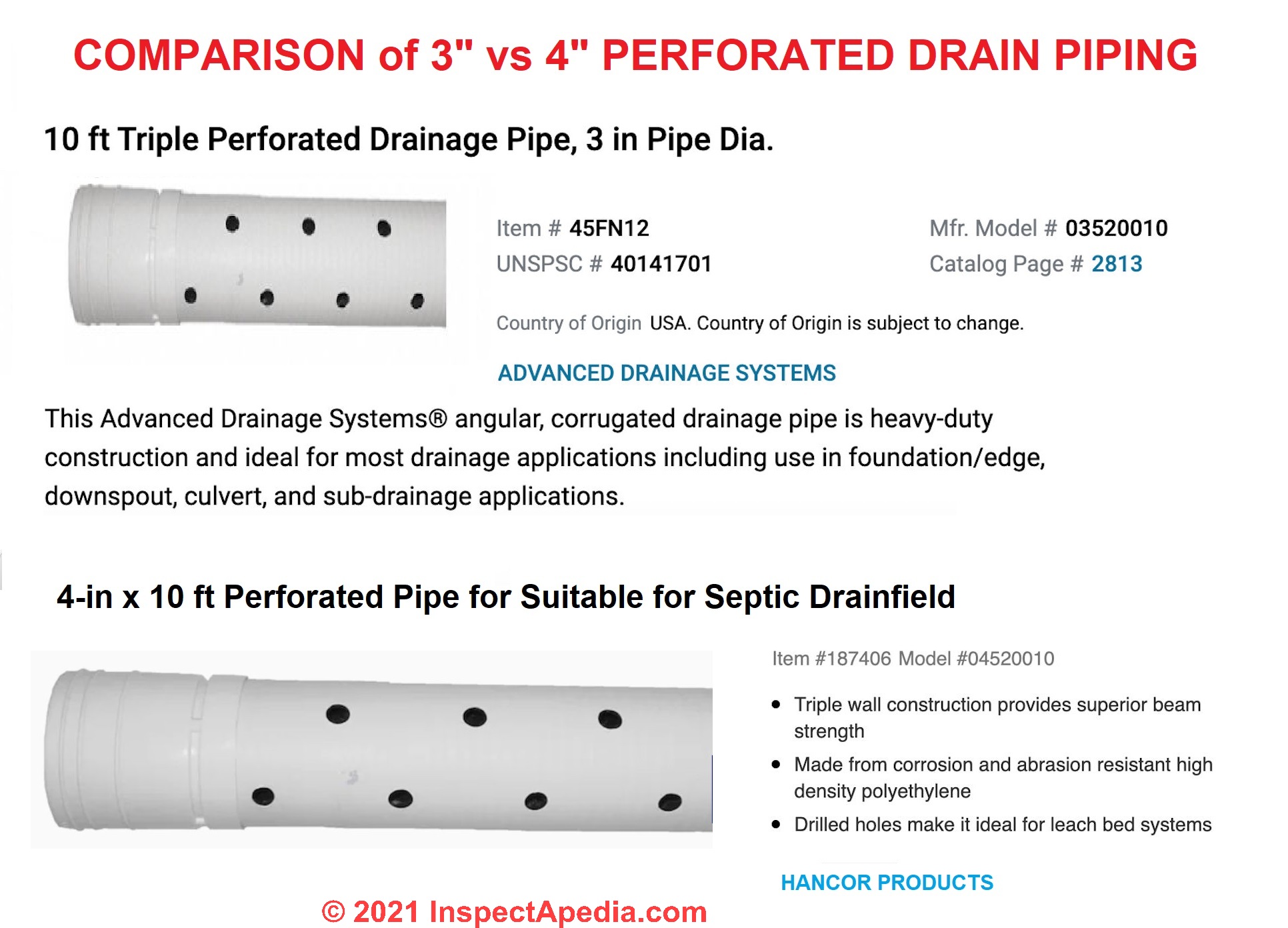
The 3-inch perforated pipe I show here, sold by grainger.com for $8.78/10 ft. length, described by the company as:
This Advanced Drainage Systems® angular, corrugated drainage pipe is heavy-duty construction and ideal for most drainage applications including use in foundation/edge, downspout, culvert, and sub-drainage applications.
NOTICE that there is no mention of its use in a septic drainfield.
The 4-inch perforated pipe intended for use in drainfield sells for about $12.27/ft (Lowes 2021) and is described as
4 in. x 10 ft. 2 hole triple wall pipe.
Triple wall construction provides superior beam strength
Made from corrosion and abrasion resistant high density polyethylene
Drilled holes make it ideal for leach bed systems
Strong and durable but lightweight
NOTICE that this 4-inch pipe is described as suitable for drainfields
Watch out: so you might infer that in addition to diameter and hole perforation pattern and location on PVC drain piping, there are strength differences that can make one product better than another for use in a septic drainfield.
Let's look at the underlying theory of changes in a drainfield pipe's ability to distribute septic effluent when you reduce its diameter.
Using a smaller diameter pipe, even by 1 inch dropping from 4" to 3" is a large reduction in the liquid carrying capacity of the system.
IF you could find perforated PVC septic drainfield piping in 3-inch diameter the disposal capacity of your drainfield pipes and thus the system would be reduced, per foot of trench length, so you'd need a larger drainfield area (more feet of trench length) to handle the same effluent disposal capacity.
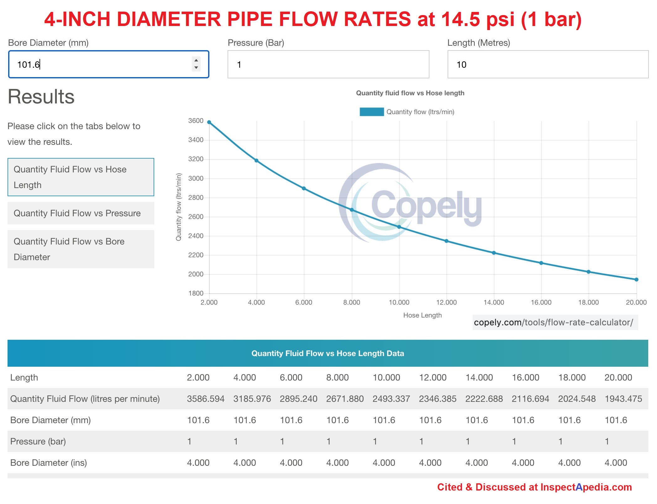
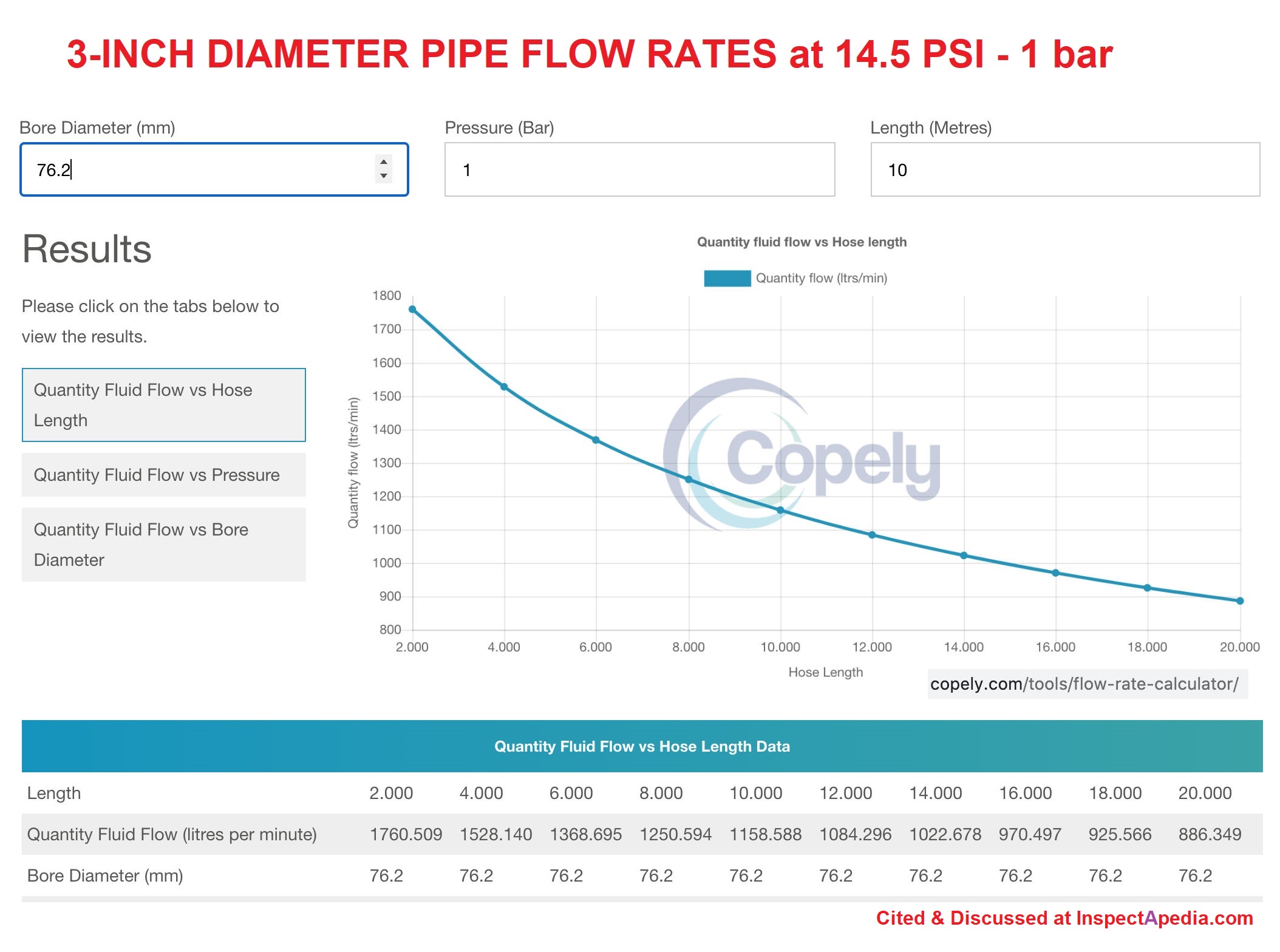
Let's use a nice online pipe flow calculator to compare the flow rates through a 4-inch pipe vs. a 3-inch diameter pipe, keeping pipe length (32.8 ft or 10 meters) and pressure (14.5 psi or 1 bar) the same. I'll show you two curves in successive images posted here.
- 4" (101.6mm) at 14.5 psi (1 bar) flow = 659 gpm (2493 lpm) using a 32.8 (10 meter) length
- 3" (76.2mm) at 14.5 psi (1 bar) flow = 306 gpm (1158.5 lpm) using a 32.8 (10 meter) length
Source: Flow rate calculator from this U.K. hose and tube developer, Copely Developments Limited, Tel: +44 (0)116 240 1500 https://www.copely.com/tools/flow-rate-calculator/
Astonishing, right? A 1-inch increase in pipe diameter, for the pressure and length I give below and for a liquid such as water or septic effluent, increases the flow rate by a factor of 1.2 - the flow rate more than doubles when we increase the diameter from 3" to 4".
Really? Now does this theory actually describe the reality of a septic drainfield?
Of course not. My calculations, in order to make mathematically sound comparisons of flow rates between pipes of different diameters, assume that the pipes are full of liquid being pushed along at 1 Bar or about 14.5 psi.
In a septic drainfield, liquid is flowing by gravity in a sloped pipe (1/8" to 1/4" per linear foot) andthe pipes are not normally ever full of liquid (except when the drainfield has failed and is clogged).
But you can see that there is a significant reduction in the ability of a pipe to carry liquid when you reduce its diameter. The effect of diameter-reduction in a gravity-fed septic drainfield system would be quite a bit less than the under-pressure calculations shown above.
Bottom line: it's better to use 4-inch perforated drainfield piping in a gravity-type septic drainfield than to use a 3-inch perforated pipe intended for other uses
For a residential septic system, I recommend using standard 4-inch diameter perforated PVC pipes designed and intended for septic drainfield use; changing to a smaller diameter would at the very least require re-calculation of the drainfield size and layout by your septic design engineer and you might also run into code-approval issues with your local building or health department.
I think that saving 40 cents per foot of drainfield pipe, might be trivial in comparison with the added cost if your engineer says you will have to dig additional feet of drainfield trench to get adequate effluent disposal by lengthening the trenches to provide sufficient effluent disposal capacity. If you take the question to your septic engineer do let us know what she has to say.
Of course all of these data points would be re-calculated if you were using a pressure-dosing septic drainfield design. That's another discussion.
Above our illustration compared 3-inch and 4-inch perforated PVC drain piping and the application or uses of each of those products.
Here is the 4-inch diameter pipe flow rate chart.
Here is the 3-inch diameter pipe flow rate chart, using the copely calculator cited thereon.
Also see WATER SUPPLY PIPE DIAMETER vs FLOW
Septic Absorption (Drainfield) Size Codes & Standards References
- SEPTIC & SEWAGE TREATMENT CODES & REFERENCES - complete set
- [5] Alaska, INSTALLERS MANUAL FOR CONVENTIONAL ONSITE DOMESTIC WASTEWATER TREATMENT AND DISPOSAL SYSTEMS [PDF] Department of Environmental Conservation, Division of Environmental Health Drinking Water and Domestic Wastewater Program, Alaska Department of Environmental Conservation, 1 Aug 2000, Anchorage Offices, 555 Coredova, Anchorage AK 99501, Tel: 907-269-7500. retrieved 17 July 2012, original source: dec.alaska.gov/water/wwdp/onsite/pdf/Certified_Installer%27s_Manual.pdf
Notice: [Quoting]
This document contains information regarding the installation of onsite sewer systems for single-family and duplex residences. It must be used by Certified Installers and homeowners who are subject to 18 AAC 72.
Additional requirements are included in 18 AAC 72. If there is a conflict between the provisions of this manual and 18 AAC 72, 18 AAC 80, or other state regulations, the regulations language controls. AEDC offices.
The regulations cited above for Alaskans can be found at alaska.gov/dec./deh/water/ci.htm - ASSE, PLUMBING DICTIONARY [PDF] 6th Ed., (2007) American Society of Sanitary Engineering, 18927 Hickory Creek Drive, Suite 220, Mokena IL 60448 USA Tel: 708-995-3019, Website: www.asse-plumbing.org
- [2] BOCA "International Private Sewage Disposal Code," 1995, BOCA-708-799-2300, ICBO-310-699-0541, SBCCI 205-591-1853, available from those code associations.
- [3] BOCA, Ontario "Manual of Policy, Procedures, and Guidelines for Onsite Sewage Systems," Ontario Reg. 374/81, Part VII of the Environmental Protection Act (Canada), ISBN 0-7743-7303-2, Ministry of the Environment,135 St. Clair Ave. West, Toronto Ontario M4V 1P5 Canada $24. CDN.
- CALIFORNIA Shasta County SEWAGE DISPOSAL STANDARDS, [PDF] Op. Cit. retrieved 2016/11/01 original source: http://www.co.shasta.ca.us/docs/Resource_Management/ehd-forms/sewage_disposal_standards.pdf?sfvrsn=0
Includes additional detailed specifications for the leach field or disposal area including setbacks, proximity to bodies of water, exposure to flooding, percolation rates, seasonal high water table, soil perc test specifications, groundwater monitoring, requirement for height above seasonal high groundwater, soil analysis, prohibition of seepage pits, and other septic system design specifications for septic tank & disposal field specifications. (Excellent detailed specifications.) - [7] CNMI, SOIL PERCOLATION TEST MANUAL [PDF] CNMI Division of Environmental Quality, PO Box 501304, Saipan, MP 96950. The CNMI Division of Environmental Quality, Gualo Rai, Saipan provides an excellent English Language manual guide for soil percolation testing. Original source: www.deq.gov.mp/artdoc/Sec6art108ID255.pdf
- [23] Massey, Howard C., The Plumbers's Handbook, Craftsman Book Company; Rev Sub edition (April 1998), ISBN-13: 978-1572180567 includes septic system design basic sketches and specifications.
- NYS DOH, RESIDENTIAL ONSITE WASTEWATER TREATMENT SYSTEMS HANDBOOK [PDF] (2012) - original source: http://www.ongov.net/health/env/documents/DesignHandbook10_24_2
- [8] OR, SOIL TEST PIT PREPARATION FOR ONSITE SEWAGE EVALUATIONS [PDF] (fact sheet) State of Oregon Department of Environmental Quality, Portland OR, 800 452-4011. PDF document. Original source deq.state.or.us/wq/pubs/factsheets/onsite/testpitprep.pdf
We recommend this excellent document that offers detail about soil perc tests, deep hole tests, safety, and septic design.
Readers of the ORegon DEQ article above should also
see SEPTIC SOIL & PERC TESTS [web article] and for testing an existing septic system, also
see DYE TEST PROCEDURE [ web article] - [22] Pennsylvania State Fact Sheets relating to domestic wastewater treatment systems include
- Pennsylvania State Wastewater Treatment Fact Sheet SW-161, Septic System Failure: Diagnosis and Treatment
- Pennsylvania State Wastewater Treatment Fact Sheet SW-162, The Soil Media and the Percolation Test
- Pennsylvania State Wastewater Treatment Fact Sheet SW-l64, Mound Systems for Wastewater Treatment
- Pennsylvania State Wastewater Treatment Fact Sheet SW-165, Septic Tank-Soil Absorption Systems
- Document Sources used for this web page include but are not limited to: Agricultural Fact Sheet #SW-161 "Septic Tank Pumping," by Paul D. Robillard and Kelli S. Martin. Penn State College of Agriculture - Cooperative Extension, edited and annotated by Dan Friedman (Thanks: to Bob Mackey for proofreading the original source material.)
- [19] USDA Septic Tank/Soil-Absorption Systems: How to Operate & Maintain [ copy on file as /septic/Septic_Operation_USDA.pdf ] - , Equipment Tips, U.S. Department of Agriculture, 8271 1302, 7100 Engineering, 2300 Recreation, September 1982, web search 08/28/2010, original source: http://www.fs.fed.us/t-d/pubs/pdfimage/82711302.pdf.
- [1] US EPA ONSITE WASTEWATER TREATMENT SYSTEMS MANUAL [online web page copy, free] Top Reference: US EPA's Design Manual for Onsite Wastewater Treatment and Disposal, 1980, available from the US EPA, the US GPO Superintendent of Documents (Pueblo CO), and from the National Small Flows Clearinghouse. Original source http://www.epa.gov/ORD/NRMRL/Pubs/625R00008/625R00008.htm
- US EPA / Otis, Richard J., Onsite wastewater treatment and disposal systems, published by the US EPA. Although it's more than 20 years old, this book remains a useful reference for septic system designers. U.S. Environmental Protection Agency, Office of Water Program Operations; Office of Research and Development, Municipal Environmental Research Laboratory; (1980)
- US EPA, SEWERS, FORCE MAIN Fact Sheet [PDF] (2000) U.S. Environmental Protection Agency,
Excerpt:
Force mains are pipelines that convey wastewater under pressure from the discharge side of a pump or pneumatic ejector to a discharge point. Pumps or compressors located in a lift station provide the energy for wastewater conveyance in force mains.
- [4] US PHS, Manual of Septic Tank Practice, US Public Health Service's 1959.
- WA DOH, BASIC PRINCIPLES of ONSITE SEWAGE [PDF] (1992) Washington State Department of Health, Office of Water, Washington D.C. USA
Also including as
APPENDIX A: WHY DO COARSE SOILS HAVE LARGER PORE SIZE & LESS SURFACE AREA? & WHY DO FINER SOILS HAVE SMALLER PORE SIZE & MORE SURFACE AREA
and
Cogger, Craig G., APPENDIX B: SEPTIC SYSTEM WASTE TREATMENT in SOIL, (1987) Washington State University Cooperatie Extension, EB1475,
Septic Tank & Drainfield Construction Health-Safety Warnings
Moved to SEPTIC TANK / FIELD INSTALLATION HEALTH HAZARDS
Reader Comments, Questions & Answers About The Article Above
Below you will find questions and answers previously posted on this page at its page bottom reader comment box.
Reader Q&A - also see RECOMMENDED ARTICLES & FAQs
On 2022-02-17 by ebcook57 - reader tips on septic drainfield piping size & spacing
@Helen Burden, Not sure what you really need. 4" pvc pipe from outlet on tank with a little fall to the beginning of the first leach line.. I use SDR35 pipe
@Tyler, five feet is code where I live
On 2022-01-31 by Inspectapedia Com Moderator - minimum distance you would want to place your drain field from your septic tank
On 2022-01-31 by Tyler
Whats the minimum distance you would want to place your drain field from your septic tank
Moderator Reply:
@Tyler,
Please take a look at the table of clearance distances for various septic system components found here:
SEPTIC TANK & FIELD CLEARANCE DISTANCES
You need to be far enough away to have adequate slope between the two and far enough away to have room for the distribution box and any other connectors.
Typical absolute minimum is five feet.
Beyond that and the minimum clearance distance is that we have already given above on this page,
distance is going to be determined by the site and the available space.
Let us know if you still have further questions.
On 2021-12-30 by Helen Burden
How do you install pipe from septic tank to drainfield
On 2021-12-30 by Inspectapedia Com Moderator - How do you install pipe from septic tank to drainfield?
@Helen Burden,
An excavator digs a trench at proper depth and slope to the drainfield area where the plumber or septic installer usually places a D-box or Distribution Box to which the drainfield lines are connected; a solid pipe is laid in the trench between tank and D-box.
On 2021-10-06 by Larry
Building a new house hooking up to existing drain field but I have to pump it to my first d-box can I run my 2”sewer pipe across the drain field to the first d-box
On 2021-10-09 by Inspectapedia Com Moderator - run 2-inch pumped effluent line to D-box
@Larry,
Yes, but take care of the installation sequence and equipment weight so as not to damage the drainfield, and depneding on your climate, you could need to deal with freeze-risk.
On 2021-08-26 by Susan Bridgit - does the drainfield have to be all in one continuous line?
We are required to have 78 lineal feet of leach line. Can this line be one continuous line or does it have to be divided into a series of trenches?
On 2021-10-09 by Inspectapedia Com Moderator - yes multiple drainfield trenches are permitted
@Susan Bridgit,
It is perfectly permissible to break up the total drainfield trench into more than one sub-line, joined from a D-box or distribution box.
In the Index to Related Articles see our description of SEPTIC D-BOX
On 2021-06-04 by Anonymous - I want to plant roses in a bed along the edge of the drainfield
I am second owner of a home with a septic system and am new to having a drainfield. I want to plant roses in a bed along the edge of the drainfield as described in the plat drawings. I dug a hole for the rose bush that is 15 inches deep and about 18" wide.
At about 5 inches down, I encountered heavy clay with lots of small and large round stones 2" to 8" in diameter. In an effort to make digging easier, I filled the hole with water. After several hours, the water level has not dropped more than 1/2".
Is the poor percolation a requirement for the soil overlying a drainfield? Should I be concerned? Can I put 12" of good soil on top of the poor soil in raised beds or would this jeopardize the drainfield?
On 2021-06-04 by Inspectapedia Com Moderator - heavy clay in septic drainfield: can I add good soil and then plant stuff?
@Anonymous,
Soil that has poor percolation means that the size of the drain field will need to be increased in order to provide sufficient absorption into the ground. Let's hope that was done in the original design.
And the article index see our article about
PLANTS OVER SEPTIC DRAINFIELDS
On 2021-05-27 by Roger Yates - do all drainfields require a mound?
There is a drainfield that may be built that does not require a mound ?
On 2021-05-28 by danjoefriedman (mod) - No, not all septic systems need to be a mound type
@Roger Yates,
Yes certainly,
if you have adequate depth of good draining soil that is sufficiently above the seasonal high water table in the ground
Then you don't need a mound or raised bed septic.
Reader Question: Can I Backfill the Septic drainfield Trenches with Wet Soil during Field Construction?
I recently installed leaching chambers and before I could backfill the trenches it rained for a couple of hours, is it ok to use the wet backfill to fill the trenches? - B.D.
Reply:
OPINION-DF: A competent onsite septic field construction inspection by an expert may find additional concerns that need to be addressed to assure a long drainfield life. That said, here are some things to consider:
- Wet soil backfill might be OK:
Provided you are installing the required gravel under and around the drainfield piping, backfilling with wet soil may not be a problem - Other factors put new septic drainfield at risk:
We say "may not be" because of not so much the soil itself, as soil is wet after backfill when it rains, but rather because depending on trench depth and how the operator runs the equipment, driving over some wet soils (depending on soil composition itself), or piling deep amounts of wet soil in a trench may compact the soil more than it would have been compacted if filled dry. - Deep soil backfill over septic means trouble:
Our opinion is that because of its added weight, filling to depths more than 30" might compact soils unnecessarily. - Driving over drainfield during construction means trouble:
But a much more serious concern would be driving the backhoe or other construction equipment over the trenches, makes for a high risk of excessive soil compaction, especially driving the equipment over the trenches. - Soil type for drainfields is important:
So soil that is not clay, and drainfield trenches that are less than 30" deep from top of gravel (over the pipes) to surface, mean you may be ok.
But driving the earth moving equipment around over the drainfield trenches themselves (or in the future driving anything over the drainfield) risks damage to the fields by soil compaction or even crushing and breaking the drainfield piping. Don't do it - backfill with care, driving equipment in the space between the drainfield trenches rather than over them.
On 2021-03-29 by (mod) - what constitutes an "abrupt" bend in sewer lines or drainfield effluent piping and what bends are permitted?
@Sarka,
A few considerations:
1. wastewater doesn't flow uphill
(putting it politely) so no drain (solid) or drainfield effluent distribution (perforated) pipe should have a belly or sag - such locations collect waste and lead to clogs
2. changes that are more-abrupt than a 45 degree sanitary elbow
or bend in sewer piping - where solids are present - will certainly invite clogging as waste slams into a pipe wall and some of it sticks - both feces and toilet paper; but I suspect that in a drainfield where there should be no large solids the risk is much smaller.
Still we might see a collection of deposits at points of impact (abrupt changes) in effluent distribution if there are small floating solids being released to the drainfield and of course those same solids clog the fields and absorption trenches as well - a good argument for using an effluent filter at the septic tank and a compelling argument for making the septic tank big-enough - see our note about settlement time
in SEPTIC TANK SIZE
and our discussion of "net free area" in the septic tank (that gives enough volume to get enough settlement time)
in SEPTIC TANK LEVELS of SEWAGE
Given that in a properly-working septic system, even un-filtered effluent ought to have only very tiny solids afloat in the effluent, so their impact and accumulation at abrupt bends or changes in the effluent piping is probably less of a worry; safest is to stay with sanitary tee and sanitary bend fittings and to avoid sharp 90s.
Septic & sewer authorities often permit use of sanitary bends such as 45s - e.g. New York's
RESIDENTIAL ONSITE WASTEWATER TREATMENT SYSTEMS HANDBOOK [PDF] (2012) - original source: http://www.ongov.net/health/env/documents/DesignHandbook10_24_2
- you won't see a discussion of abrupt pipe direction change in this book but it's still got good design basics.
Bottom line: best practice in an effluent distribution system is to restrict bends in the effluent piping to 1/16 bends wherever possible, noting that in typical septic codes & standards 45 deg. sanitary elbows are permitted.
And where bends are unavoidable, ask your septic designer if you need to increase the slope or pipe diameter slightly to be sure of adequate flow.
Also see our discussion of this abrupt change in sewer piping concern
at SEWER / SEPTIC LINES at STEEP SITES
On 2021-03-29 by Sarka - what is considered an "abrupt Change in direction" of a leaching (absorption) trench?
Question: Hello what is considered an "abrupt Change in direction" of a leaching (absorption) trench?
On 2021-03-29 by (mod) - Plumbing Code & Definitions of "Abrupt Change" bends & Approved Fittings
@Sarka, great question; IMO a good directional change 1/6 bend or less. However the most-common is a 45 degree bend (sometimes mis-named a 90) sanitary wye or tee.
There are similar of "abrupt change" or "bend" pertinent to drain piping and to septic system design perhaps best summarized in the UPC or Uniform Plumbing Code:
UPC 706.1 Approved Fittings.
Changes in direction of drainage piping shall be made by the appropriate use of approved fittings and shall be of the angles presented by a one-sixteenth bend, one-eighth bend, or one-sixth bend, or other approved fittings of equivalent sweep.
706.2 Horizontal to Vertical.
Horizontal drainage lines, connecting with a vertical stack, shall enter through 45 degree (0.79 rad) wye branches, 60 degree (1.05 rad) wye branches, combination wye and one-eighth bend branches, sanitary tee or sanitary tapped tee branches, or other approved fittings of equivalent sweep.
706.3 Horizontal to Horizontal.
Horizontal drainage lines connecting with other horizontal drainage lines shall enter through 45 degree (0.79 rad) wye branches, combination wye and one-eighth bend branches, or other approved fittings of equivalent sweep.
706.4 Vertical to Horizontal.
Vertical drainage lines connecting with horizontal drainage lines shall enter through 45 degree (0.79 rad) wye branches, combination wye and one-eighth bend branches, or other approved fittings of equivalent sweep.
Other uses of and warnings\s about abrupt bends or changes in sanitary drains or septic systems:
Egs:
" Toe of Slope — The base or bottom of a slope at the point where the ground surface abruptly changes to a significantly flatter grade"
Reference:
Kirk, Douglas, "UPC — Change of Direction", June 2016, current source: https://www.linkedin.com/pulse/upc-change-direction-douglas-kirk
On 2021-03-29 by Sarka
thank you for responding and - this question relates specifically to the absorption trench (leaching trench) - the code says:
"They (absorption trenches) need not be perfectly straight but abrupt changes in direction shall be avoided." There is no definition of "abrupt" for this condition. Any thoughts? Thank you!
On 2021-03-24 by M M - footer pipe recommendations on pressure dosing effluent system
Hi, thanks for your awesome resource it's really helped a lot while working on all the many things that have gone wrong with our lake house.....
About to start working on my (dark) Greywater pressure dosing system after leaving it over winter, and I have decided on and finished the first stage tank, second stage pumping chamber, and need to build the Drainfield. I have determined the proper size and layout, but what I cannot seem to find a good answer to, is this:
In a pressure dosed system where the pump shoots the greywater into three perforated pipes in a Gravel Based (gravel below, dirt after about 6 inches above the pipe) Mound,
Would you recommend 1st of all the "footer pipe" that some designs show, where the end of the leach field is tied together? I plan to put three in line cleanouts, so I would need wye fittings to add this, but if there is a benefit, I will.
Also, 2nd of all, Would you recommend a Vent, to introduce oxygen into the leach field and allow good movement of water? I considered drilling a hole in the top of the "footer pipe" off to the side of the main laterals (as to try to prevent water from rushing up the vent), and just running a 1" or 1 1/2" flexible black piping out of the mound and staking it in (with a mushroom / rain cap) in some nearby bushes.
I worry that maybe it will compromise the "pressure" but again im not sure.
Finally, what about the first and second stage tanks? They'll be fairly air tight, do they need vents? It would be easier to do before I landscape even though the tanks are in the ground and most of the dirt is on top.
So to make that more clear, does a pressure-dosed perforate pipe system require a footer pipe and a vent to introduce air into the drainfield and to allow good flow? What about vents for tanks? Will be building this ASAP when the ground thaws. Thank you very much,
Mike
On 2021-03-25 1- by (mod) - pressure dosing system design
@M M,
I can't provide an authoritative answer on this but I can take a stab at your questions.
In the article above we have:
(v) Maximum dimensions for pressure distribution: Using pressure distribution with a center manifold, a bed system shall have maximum dimensions of 205 feet by 20 feet.
So we see that there is an anticipation of a distribution manifold that sends effluent into the various legs - I'm not sure if your footer pipe is an addition of distribution area or something else.
I have seen people add "vent" into mounds and drainfields but in my OPINION they do little to provide oxygen to the volume of soil that actually receives the effluent. More important is the depth of the distribution piping: deeper means less oxygen - and of course important to field life is the clarity of the effluent being delivered.
You need to review pumping chamber design with your septic engineer; in general, if a tank is small and air-tight, the effluent dosing pump could run into vacuum problems that a vent would alleviate.
If you don't have a septic engineer on board I recommend hiring one; I'm doubtful that in most communities the local approving authorities will approve a DIY pressure dosing septic system plan that hasn't benefited from soil testing, site characteristics mapping, and an expert's sign-off.
@M M, just to clarify in case it's helpful:
a pressure dosing system - is a design that takes care to send effluent to the fields only at intervals rather than continuously as wastewater enters the septic tank
a pumping system - is a design that uses a separate pumping chamber to send clarified effluent to the drainfield not based on a timer (pressure dosing) but rather simply as usage fills the pumping chamber to a sufficient level;
Either of these can pump UP to a location such as a raised-bed septic or mound system which is what we see installed when the soil perc rate is poor.
You can find those designs in the ARTICLE INDEX
On 2021-03-25 by M M
Yes I am doing this DIY with family, what an ordeal. We did some informal soil perc testing and a few deep dig in channels before we started (partially just to find the lines, but it helped to examine the soil). I hadn't considered the implications of going with a pressure dosing system instead of gravity in that the county might require a sign off from an engineer.
The reason I went with a pump is because the old, failed leach field is in the only good spot for gravity.
The footer pipe, is something I saw in various diagrams online,. I assumed it was for either an extension of the leach field or for ensuring air circulation in the field. I guess since I can't put a filter in the settling tank (mostly inaccessible) I will put a tee filter in the inlet to the pump tank to clarify the effluent. Lots to think about. Thank you!
On 2020-12-26 by john stirmel jr - how far in from the end do they typically come in to install the septic field inspection pipes?
I have a drain field that is 70’ long 3’with of drain tile or dog houses and 6’ apart my question is how far in from the end do they typically come in to install the inspection pipes as mine are buried and I need to find them for inspection to sell my house the frost is a foot and a half so I’m having one hell of a time
On 2020-12-26- by (mod) - installation of new inspection pipes in an existing older septic system
John
installation of inspection pipes in an existing older septic system is a bit unusual in my experience so I don't have a standard answer for you about exactly where those would be installed.
For the more it sounds to me as if a contractor is having you do work that they're being paid to perform since the installer would normally be the person required to locate the pipe to which they're planning on making a connection.
It's also unclear exactly why you're having these installed now.
In any event if you need to locate the exact routing of your septic lines that's easily done by using drain tracing equipment. Typically that's a metal flexible snake that's inserted into the lines and that is sensed by a transmitter receiver.
On 2020-09-12 by Nathaniel - any way to bring in top soil (loam, sandy loam, etc.) to achieve the absorption field required?
I am being told that a lot I want to purchase near Charlotte, NC on Lake Norman cannot perc because the soil depth is shallow (as little as 8” in places). I am willing to do a pre-treatment system, but am told that I would need a drain absorption field which cannot be achieved with the shallow soil.
My question is: any way to bring in top soil (loam, sandy loam, etc.) to achieve the absorption field required? Seems like this would be similar to a mound system, but am told I still cannot do that even with pre-treatment.
On 2020-09-12- by (mod) - definitely: it's common to bring in soil to build a septic mound system
Nathaniel
Most likely your local building or health department will accept a raised bed septic or a septic mound system - those involve bringing in soil to build an above-ground effluent treatment system, just as you suggest.
IF your local authorities won't accept a septic mound or similar system ask if they'll accept an aboveground mini wastewater treatment system that is complete - a packaged system that only discharges clean water.
On 2020-09-08 by co8a - septic system depth to avoid freezing in Minnesota
What should be the thickness of the soil above the pipes so that they do not freeze in winter in Minnesota?
...but if the holes are in the pipe for 4 and 8 hours, then a small amount of gray water remains in it. Can the water freeze in cold weather? How can you protect yourself from this, especially in the first year of the construction of the mound systems?
Hello! How to protect a perforated pipe (mound system) from freezing in winter?
On 2020-09-09 - by (mod) -
Anon:
In northern MN the frost line can be 6-8 feet below the surface; I've seen drainfields buried that deep, but unfortunately those drainfields, while they may "dispose" of septic effluent, do not treat it effectively, as there is not much aerobic bacteria (needed for effluent treatment) at that soil depth.
So what septic mounds and other drainfields rely upon in cold climates such as Minnesota are active use. The combination of frequent dosing with warm household water and the heat produced by bacterial action are generally sufficient to help keep a drainfield from freezing.
A brand new field might require extra measures such as straw cover at least until there is a protective covering of deep snow.
In normal use the mound septic gets enough warm water as to avoid freezing, but yes, people often insulate a new mound with straw or hay.
On 2020-06-09 by Connie Magistrelli - clearance distance: leach field to structure?
How close to a leach field can something, a structure, be built?
On 2020-06-23 - by (mod) -
Connie
Please see all of the clearance distances given at
CLEARANCE DISTANCES, SEPTIC SYSTEM https://inspectapedia.com/septic/Septic_Clearance_Distances.php
and let me know if that leaves you with any questions.
On 2020-04-20 by Howard - distance from septic tank to drainfield
My septic system is 48 years old.
How far is the drain tank from the septic tank
On 2020-05-14 - by (mod) -
Howard
Sorry but there is no standard distance.
In the ARTICLE INDEX you'll find articles on how to find the septic tank, distribution box, and drainfield.
On 2020-04-09 by Que - put tar paper over septic drainfield pipes?
When running a drain field wat is the typical layout. Before tuning my pipes. Do I put I think it’s called tar paper down first the my rock or gravel or rock them paper.
On 2020-04-09 - by (mod) -
Que
Typical drainfield layout is parallel trenches, about 5 feet apart.
You would never put tar paper (roofing felt) nor any other impermeable or low-permeable material under or along side nor immediately over the leachfield pipes, though some installers might include a soil barrier synthetic fabric at the top of the drainfield trench under the dream and hope that we'll slow soil penetrating and clogging the piping.
In my OPINION that's not the best thinking. The proper quantity of gravel under, around, and over top of the piping is what's critical along with proper trench size and slope.
Take a look at the rest of the articles in this series to see more details about drainfield construction starting with the article SEPTIC DRAINFIELD SHAPE recommended at the More Reading link above.
On 2020-04-08 by Paul Lloyd - septic design for animal shelter
We are an animal shelter in South East Asia with approx 1000 resident dogs and cats. We have a variety of septic tanks and the overflow is pumped to one location and through filters to our lake. We recently acquired a field adjacent to the shelter approx 160 M x 50 M.
It is flat but approx. 1.3 M lower than our existing land. The plan is to make it in to a drain field and then back fill to the level of our land. The sub soil is good for a meter then clay below. What type of drain field would be best?
On 2020-04-08 - by (mod) -
I cannot be confident of a right design for your drainfield given so little information - an onsite septic engineer would be more-helpful.
But in general, for the location you describe, the best design is one that absolutely assures that the bottom of the drainfield absorption trenches is at least two feet above the seasonal high water table in the area.
In your area with clay just a meter below the surface, you may not have an effective effluent absorption system that actually treats the effluent; you need sufficient soil, above any nearby water table or body of water, to provide time and soil and bacteria to actually treat the septic pathogens in the effluent.
You don't want to end up just leveling the drainfield to the same height as a surrounding area, not to mention sewage that may already be contaminating the nearby lake.
Instead, a raised bed septic or mound system design brings in enough fill to bring the absorption bed to the necessary height.
In the ARTICLE INDEX you'll find links to article describing SEPTIC MOUND SYSTEMS and RAISED BED SEPTIC SYSTEMS
On 2020-03-29 by John Hawkins - distance between drainfields?
What is Min. dist. allowed between drain fields ?
On 2020-03-29 - by (mod) -
John
Are you asking about alternating drainfields on a single building site? You'd have at least 8 ft.
Or are you asking about drainfields on neighboring, independent properties? - see CLEARANCE DISTANCES, SEPTIC SYSTEM https://inspectapedia.com/septic/Septic_Clearance_Distances.php
On 2020-03-04 by David - maximum distance from septic tank to D-Box?
What is maximum length of line between septic tank and diverter box ?
On 2020-03-04 by Anonymous
David
There's not a code-specified maximum distance between septic tank and the D-box, but there will be a technical or practical distance limitation since the main effluent line from tank to D_box and from D-box to absorption trenches has to slope (typically 1/8" to 1/4" per foot).
A very long run that pushes drainfield lines too deep will have you building a system that lacks soil oxygen and thus doesn't treat the effluent adequately (not enough bacterial action) so then contaminates the environment, groundwater, wells.
...
Continue reading at SEPTIC DRAINFIELD SHAPE or select a topic from the closely-related articles below, or see the complete ARTICLE INDEX.
Or see SEPTIC DRAINFIELD SIZE FAQs - reader questions & answers.
Or see these
Recommended Articles
- NEW YORK STATE 75-A.8 SUBSURFACE TREATMENT of EFFLUENT
- SEPTIC DRAINFIELD INSPECTION & TEST - home
- SEPTIC DRAWINGS
- SEPTIC SOIL & PERC TESTS
- SEPTIC SYSTEM DESIGN ALTERNATIVES - home
- SEPTIC SYSTEM DESIGN BASICS
- SEPTIC TANKS - home
- U.K. OFF-GRID SEPTIC REGULATIONS & SEWAGE SYSTEMS
- U.S. SEPTIC AUTHORITIES & DESIGN SPECIFICATIONS - Septic codes & regulations for each US State or Territory
Suggested citation for this web page
SEPTIC DRAINFIELD SIZE at InspectApedia.com - online encyclopedia of building & environmental inspection, testing, diagnosis, repair, & problem prevention advice.
Or see this
INDEX to RELATED ARTICLES: ARTICLE INDEX to SEPTIC DRAINFIELDS & DBOXES
Or use the SEARCH BOX found below to Ask a Question or Search InspectApedia
Ask a Question or Search InspectApedia
Questions & answers or comments about septic drainfield or soakaway bed size or capacity requirements & design.
Try the search box just below, or if you prefer, post a question or comment in the Comments box below and we will respond promptly.
Search the InspectApedia website
Note: appearance of your Comment below may be delayed: if your comment contains an image, photograph, web link, or text that looks to the software as if it might be a web link, your posting will appear after it has been approved by a moderator. Apologies for the delay.
Only one image can be added per comment but you can post as many comments, and therefore images, as you like.
You will not receive a notification when a response to your question has been posted.
Please bookmark this page to make it easy for you to check back for our response.
Our Comment Box is provided by Countable Web Productions countable.ca
Citations & References
In addition to any citations in the article above, a full list is available on request.
- ASSE, PLUMBING DICTIONARY [PDF] 6th Ed., (2007) American Society of Sanitary Engineering, 18927 Hickory Creek Drive, Suite 220, Mokena IL 60448 USA Tel: 708-995-3019, Website: www.asse-plumbing.org
- NYS DOH, RESIDENTIAL ONSITE WASTEWATER TREATMENT SYSTEMS HANDBOOK [PDF] (2012) - original source: http://www.ongov.net/health/env/documents/DesignHandbook10_24_2
- US EPA, SEWERS, FORCE MAIN Fact Sheet [PDF] (2000) U.S. Environmental Protection Agency,
Excerpt: Force mains are pipelines that convey wastewater under pressure from the discharge side of a pump or pneumatic ejector to a discharge point. Pumps or compressors located in a lift station provide the energy for wastewater conveyance in force mains. - WA DOH, BASIC PRINCIPLES of ONSITE SEWAGE [PDF] (1992) Washington State Department of Health, Office of Water, Washington D.C. USA
Also including as
APPENDIX A: WHY DO COARSE SOILS HAVE LARGER PORE SIZE & LESS SURFACE AREA? & WHY DO FINER SOILS HAVE SMALLER PORE SIZE & MORE SURFACE AREA
and
Cogger, Craig G., APPENDIX B: SEPTIC SYSTEM WASTE TREATMENT in SOIL, (1987) Washington State University Cooperatie Extension, EB1475, - [1] US EPA ONSITE WASTEWATER TREATMENT SYSTEMS MANUAL [online copy, free] Top Reference: US EPA's Design Manual for Onsite Wastewater Treatment and Disposal, 1980, available from the US EPA, the US GPO Superintendent of Documents (Pueblo CO), and from the National Small Flows Clearinghouse. Original source http://www.epa.gov/ORD/NRMRL/Pubs/625R00008/625R00008.htm Onsite wastewater treatment and disposal systems, Richard J Otis, published by the US EPA. Although it's more than 20 years old, this book remains a useful reference for septic system designers. U.S. Environmental Protection Agency, Office of Water Program Operations; Office of Research and Development, Municipal Environmental Research Laboratory; (1980)
- [2] "International Private Sewage Disposal Code," 1995, BOCA-708-799-2300, ICBO-310-699-0541, SBCCI 205-591-1853, available from those code associations.
- [3] "Manual of Policy, Procedures, and Guidelines for Onsite Sewage Systems," Ontario Reg. 374/81, Part VII of the Environmental Protection Act (Canada), ISBN 0-7743-7303-2, Ministry of the Environment,135 St. Clair Ave. West, Toronto Ontario M4V 1P5 Canada $24. CDN.
- [4] Manual of Septic Tank Practice, US Public Health Service's 1959.
- [5] "Installers Manual for Conventional Onsite Domestic Wastewater Treatment and Disposal Systems", Department of Environmental Conservation, Division of Environmental Health Drinking Water and Domestic Wastewater Program, Alaska Department of Environmental Conservation, 1 Aug 2000, Anchorage Offices, 555 Coredova, Anchorage AK 99501, Tel: 907-269-7500. retrieved 17 July 2012, original source: http://dec.alaska.gov/water/wwdp/onsite/pdf/Certified_Installer%27s_Manual.pdf [Copy on file as Alaska_Certified_Installer's_Manual.pdf].
Notice: [Quoting]
This document contains information regarding the installation of onsite sewer systems for single-family and duplex residences. It must be used by Certified Installers and homeowners who are subject to 18 AAC 72. Additional requirements are included in 18 AAC 72. If there is a conflict between the provisions of this manual and 18 AAC 72, 18 AAC 80, or other state regulations, the regulations language controls. AEDC offices.
The regulations cited above for Alaskans can be found at http://www.alaska.gov/dec./deh/water/ci.htm - [7] Percolation Testing Manual, CNMI Division of Environmental Quality, PO Box 501304, Saipan, MP 96950
- [8] Test Pit Preparation for Onsite Sewage Evaluations, State of Oregon Department of Environmental Quality, Portland OR, 800 452-4011. PDF document. We recommend this excellent document that offers detail about soil perc tests, deep hole tests, safety, and septic design.
- [9] Wells and Septic System, Alth, Max and Charlet, Rev. by S. Blackwell Duncan, $ 18.95; Tab Books 1992.
- [17] Thanks to reader Michael Roth for technical link editing 6/29/09.
- [19] Septic Tank/Soil-Absorption Systems: How to Operate & Maintain [ copy on file as /septic/Septic_Operation_USDA.pdf ] - , Equipment Tips, U.S. Department of Agriculture, 8271 1302, 7100 Engineering, 2300 Recreation, September 1982, web search 08/28/2010, original source: http://www.fs.fed.us/t-d/pubs/pdfimage/82711302.pdf.
- The NSFC Products List has an excellent list of design manuals/modules National Small Flows Clearinghouse (NSFC) now (2019/12/13) hosted at http://www.nesc.wvu.edu/ Tel: 304-293-4191 e-mail info@mail.nesc.wvu.edu. telephone 800-624-8301
- In addition to citations & references found in this article, see the research citations given at the end of the related articles found at our suggested
CONTINUE READING or RECOMMENDED ARTICLES.
- Carson, Dunlop & Associates Ltd., 120 Carlton Street Suite 407, Toronto ON M5A 4K2. Tel: (416) 964-9415 1-800-268-7070 Email: info@carsondunlop.com. Alan Carson is a past president of ASHI, the American Society of Home Inspectors.
Thanks to Alan Carson and Bob Dunlop, for permission for InspectAPedia to use text excerpts from The HOME REFERENCE BOOK - the Encyclopedia of Homes and to use illustrations from The ILLUSTRATED HOME .
Carson Dunlop Associates provides extensive home inspection education and report writing material. In gratitude we provide links to tsome Carson Dunlop Associates products and services.
 | HOME | ABOUT | ASK a QUESTION | CONTACT | CONTENT USE POLICY | DESCRIPTION | POLICIES | PRIVACY | |
| © 2024 - 1985 Publisher InspectApedia.com - Daniel Friedman | |||||||||