
InspectAPedia® FREE Encyclopedia of Building & Environmental Construction, Diagnosis, Maintenance & Repair |
Question? Just ask us! InspectAPedia
|
 Drain Back Valve & Snifter Valve Installation or Replacement Specifications
Snifter Valves & Drain Back Valve Installation Specifications
- POST a QUESTION or COMMENT about sifter valves, Dill valves, and how the snifter valve works together with US Gauge & Similar Type 310WJ, Type 300SL, or Type 6 Rectangular Air Volume Controls
Installation & Repair of Drain Back Valves, Bleed-Back Systems & Snifter Valves & AVCs:
This article explains where & how to properly-install a snifter valve, bleed-back valve or drain back valve and air volume control valve on a well or lake water supply system. How to repair or replace parts in the snifter valve. Specifications on the locations, distances, heights, and drainage points for well or lake water piping drain-down systems used to avoid freezing and to keep a proper air charge in the water tank.
This article series describes snifter valves and drain-back valve , what they are, how they regulate air in a well water system, how they work with an air volume control,& how these components protect well piping against freezing. We describe how & where the snifter valve, drainback valve and air volume control are installed & what they look like.
InspectAPedia tolerates no conflicts of interest. We have no relationship with advertisers, products, or services discussed at this website.
Drain Back Valve & Snifter Valve Installation, Repair or Replacement
Location of the Snifter Valve on a Well or Lake Water Piping System
It's not complicated to repair or replace the above-ground components of a drain-back & snifter valve system as those parts are readily accessible. Sometimes.
[Click to enlarge any image]
[Click to enlarge any image]
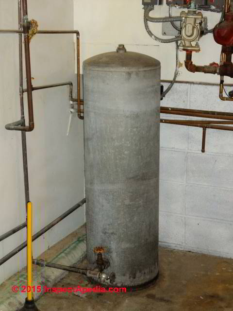
At above left we see a typical galvanized steel bladderless water pressure tank on a northern Minnesota home well water supply system. The pump is in the well - a submersible pump unit. But at above left we see only a house water supply line connected (along with a drain) at the bottom of the water tank (green arrow).
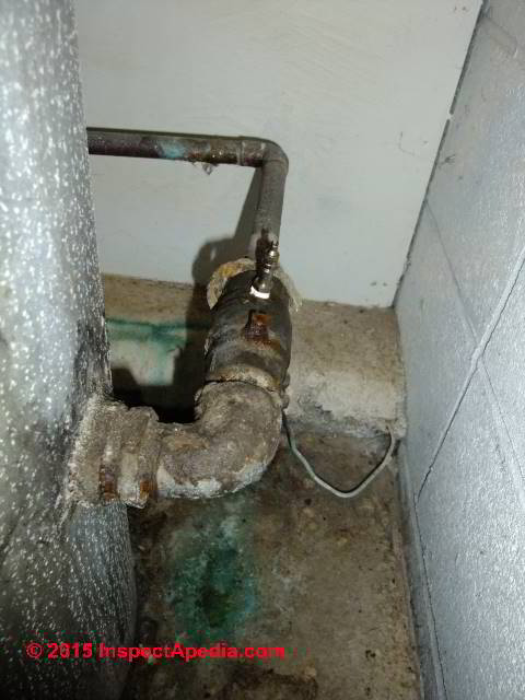
Where are the snifter valve and check valve? Take a look at the second photo at above right: the water inlet line from the well pump enters through a check valve mounted on the bottom of the same tank. But on it's back side not visible in our first picture. And atop that check valve (above right) is the snifter valve (blue arrow).
Where the snifter valve - air inlet is installed on a drain-back water system
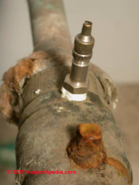
The snifter valve is installed
- Ahead of the water pressure tank outside the well casing (typically on a check valve at or close to the bottom of the water pressure tank)
or - Inside the sell casing under the well cap or seal and at least 5 feet above the drain-back valve.
Watch out: in this location the air inlet valve only protects the upper portion of the well piping in the well: it may not fully drain and freeze-protect well piping between the well and the building it serves
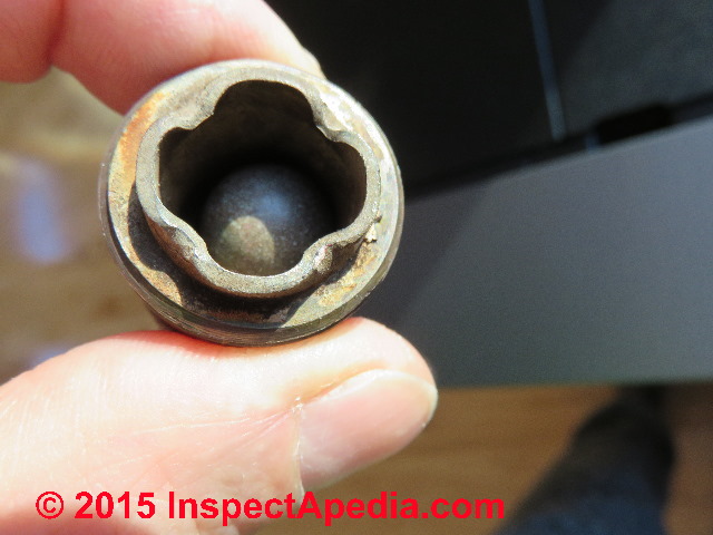
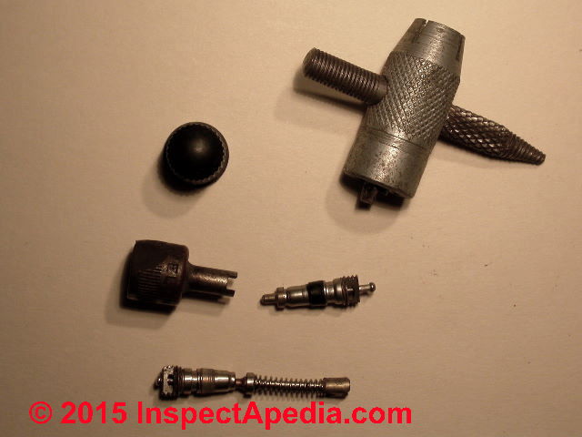
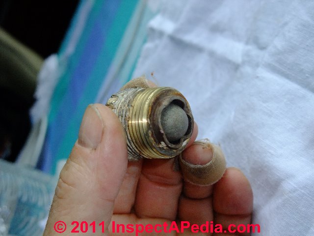
Watch out: Be sure that you replace the internal snifter valve core with the proper parts. Using a valve stem core from an auto supply store may stop leaks at the snifter valve but the spring will be too strong to allow the valve to admit air into the system when required - it will no longer work.
You'll regret this easily-made error as the result can be frozen well piping or a short cycling or ruined well pump. Our photo at above right illustrates two different valve stem cores two different caps (the solid cap doesn't belong on a snifter valve as it won't admit air) a valve stem core tool.
Watch out: the spring in the Snifter Valve located at the water pressure tank is a low-pressure spring.
If you set out to repair a leaky Schrader valve at this location don't just screw in an automotive type Schrader valve - that type will be operating at a pressure range too high for this purpose.
Watch out also: the typical air valve or Schrader Valve mounted on bladder type water pressure tanks and on some other water systems and intended for use in adding air to a pressure tank may not be serving as Snifter Valves or air admittance valves.
Location of the Drain Back Valve or Bleed-Back Valve or Bleeder Orifice on a Well or Lake Water Piping System
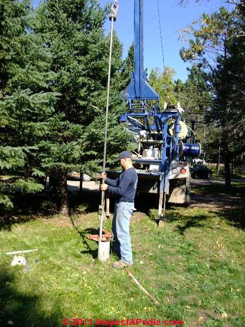
It's more trouble(and expense) to check and replace the drain-back valve located on a tee in the well piping.
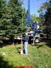
To replace the drain back orifice and valve shown immediately above it will be necessary to open the well and pull the well piping up sufficiently to reach and replace the device - a larger expense and more trouble as you can see in our photo (Rasmussen Well Drilling, Inc. , & DJ Friedman).
A well service rig including crane and winch are needed to pull the well piping.
The drain back valve is installed
- Five feet or more lower than the elevation of the snifter valve or air inlet valve on the well piping system
- A maximum vertical distance of 18 feet from the closest drain faucet in the water system
- Inside the well casing in the well bore or for some systems elsewhere along the well piping system in an area where the valve can drain water from the well piping to a location where the water won't create a problem, protected from freezing, and not buried (burying the drainback valve is likely to prevent it from working).
- Below the frost line in the well bore
- Above the top of the highest level reached by water in the well bore or casing - above the well's static head top.
- No check valve can be installed in this pipe section that would prevent water system drain-back.
- The position of the drain back or bleed-back valve must be horizontal for older ball-type valves such as the one shown in this article series
but some other drain back valves using a positive closing mechanism such as the FloMatic® Model 70 automatic drain valve can be installed in any position vertically or horizontally.
This cute little air well piping frost protection component is located inside the well on a tee on the well piping above the static head or about ten feet from ground surface in most installations.
See WELL DYNAMIC HEAD & STATIC HEAD DEFINITION
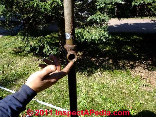
Our first photos at above left shows the well piping tee where the well service company worker has already removed the drain-back valve detailed in our photographs immediately above and again below. Immediately above you can see the ball that operates the opening and closing of this valve (the ball is in the "open" or "drain back" position).
Our bleed-back valve photo just below shows the water outlet opening valve.

As you can see this is a pretty small opening, about 1/8" in diameter, which is why if there is a lot of well piping to drain above the frost line you may want more than one of these little devices.
If the well pump is a submersible unit (located in the well) and if also the water pressure tank is a non-bladder type, there could also be one or even two of these drain-back valves installed on vertical section(s) of well piping inside the well. But they have to be above the top of the high water level in the well as well as below the frost line or the system won't work.
When the submersible well pump is running the well piping is under pressure and this drain back valve is closed by that pressure inside the well piping. Water is pumped up in the well pipe and into the building water supply system.
When the submersible well pump stops running, the snifter valve air inlet located at a check valve near the water pressure tank admits air into the well piping.
In turn that air allows water inside the well piping to drain back into the well through the small opening in the drain-back valve's drain opening.
Our photos below show how these valves function to open and close in response to water pressure in the piping.
Location of the Air Volume Control for Drain Back Systems for Freeze Protection of Well or Lake Water Piping
And where is the air volume control on this system. That device too was mounted on a tapping (or "tank bung") on the back side of the tank at the middle of the tank's height.
The pressure tank used on these systems is normally a steel or fiberglass water tank that does not make use of an internal bladder to keep water and air in the tank separate.
Rather, the excess air in the tank (pushed up from the air-filled well or lake water piping) needs to be vented by an air volume control mounted at the about the middle of the pressure tank's side.
At above left we see the bladderless galvanized steel water pressure tank snuggled into the corner of a heated garage. The air volume control and snifter valve are not visible at above left - they're on the other side of this water tank.
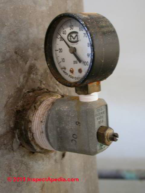
Our photo at above right shows the air volume control. The blue arrow points to the air vent on this AVC device. Not visible is the AVC float mechanism inside the tank.
That part of the AVC rises or falls according to the water level in the pressure tank. The float opens (on water level fall) the air vent on this AVC to vent excess air in the pressure tank.
When water in the tank reaches a little below the level of the AVC valve itself, the float closes the vent to stop releasing air from the tank, thus keeping the proper air charge in this bladderless pressure tank.
Adjustment of excess-air-releasing air volume controls such as the US Gauge type WJ AVCs is
An orange arrow points to the water tank pressure gauge, but of course you knew that.
Watch out: if the AVC stops working on a bleed-back-valve (or drain-back valve, or snifter valve) system the symptom may not be frozen pipes but rather air discharge at plumbing fixtures. Unless the AVC can vent the excess air we'll see air blasting out of nearby faucets or other plumbing fixtures.
That's because on a drain-back system the air injected into the well piping by the snifter valve is pushed up into the pressure tank at the next well pump on-cycle.
See AIR VOLUME CONTROLS, WATER TANK for details about these devices and how they work.
What about the location of other water pump controls such as the pressure control switch and for larger capacity well pumps the pump relay switch?
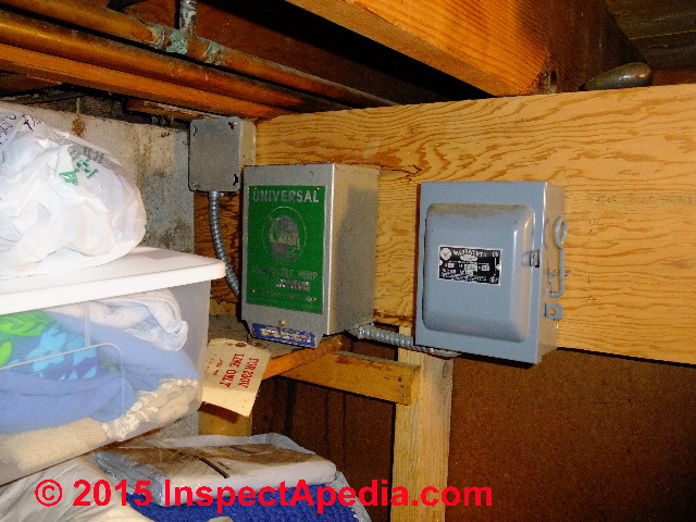
The pressure control switch for our model system is not so easy to see: it's mounted nearer the top of this pressure tank and mostly hidden from view (black arrow in the photo at above left).
The pressure control switch on this system talks to a pump relay switch that is nowhere in sight.
We found that control below the home's entry stairs in a tiny crawl space (red arrow in the photo at left). Sometimes it takes some exploring to find all of the water system components and controls.
Reader Comments, Questions & Answers About The Article Above
Below you will find questions and answers previously posted on this page at its page bottom reader comment box.
Reader Q&A - also see RECOMMENDED ARTICLES & FAQs
On 2020-11-22 by (mod) - Do bleeder valves come with different degrees of resistance?
Possibly but not that I've seen; let's ask your well driller.
On 2020-11-18 by Paul
Do bleeder valves come with different degrees of resistance? I replaced a bleeder valve located 10 feet down the well along a 1.25 inch galvanized pipe and it will not open to release the water. It is like the weight of the 10 foot column of water is stronger than the spring in the bleeder valve.
What should I replace this valve with to assure the release of water when the pump is off?
On 2020-11-17 by (mod) - How can I prevent a drainback valve from clogging with sediment?
Thanks Paul, that's a question I've not considered nor encountered.
Do we have to accept a high level of sediment in the water supply? For example, should we just move the submersible pump up a few feet to avoid that problem if sediment is being drawn from the bottom of the well?
If the pump is well off the bottom, is the casing damaged and leaking muck into the well? Inspect by well camera; if that's the case you want to fix the casing with a well casing sleeve rather than keep contaminating the water supply.
FInally, if the well casing is sound and the sediment is innate in your water supply at such a high level that it clogs up the drainback valve then don't you want to install a high capacity filter ahead of the pressure tank?
With a filter installed you might use a combination of check valve and back loop to send filtered water back down the well pipe at pump shutoff. That won't eliminate the sediment-contaminated water in the pipe on the well side of the filter but it'll dilute it and it'll avoid sending back sediment that otherwise will accumulate in your pressure tank and house piping.
Let me know what you think and let me know if your local well driller has other suggestions.
On 2020-11-16 by paul
How can I prevent a drainback valve from clogging with sediment? Do they come with different spring strengths depending on how deep they are located in the well? Mine is 10 feet down in a 1.25 inch well pipe.
I replaced it with a new 1/2 inch valve and it will not drain. The snifter valve works but the drainback valve is not releasing water.
All I can figure is the weight of the 10 foot colume of water is keeping the valve closed. Any suggestions as to what I should replace this new drainback valve with?
On 2020-09-16 - by (mod) -
Anon
NOt likely; the drainback valve is going to be some distance down in the well, but above the water level; it'd have to be within arm's reach of the top and in a large diameter casing even if all we wanted to do was to unscrew and replace the check valve insert.
On a 108ft well you've probably got close to 100 ft of pipe + weight of the pump; the pros use a hoist that clamps onto pipe sections; amateurs use a tripod and winch; the risk is, of course that you break a pipe and drop the whole shebang back into the well;
That happens enough that there's a whole world of WELL PIPE GRABBING TOOLS including discussed here at Inspectapedia.com
On 2020-09-15 by Anonymous
Can a drain back valve be located, inspected and/or replaced inside the well without pulling up the well line? Can a 180 foot well line be pulled up by a DIY homeowner? If so, how?
On 2020-09-01 by (mod) - Can a Stop Check Valve be used to replace a normal check valve on a standard residental well system.
Sounds like you need a check valve
On 2020-09-01 by Paul tu.tall@hotmail.com
Can a Stop Check Valve be used to replace a normal check valve on a standard residental well system. Would you recommend installing a Stop Check Valve to reduce pump cycling?
On 2020-09-01 by Paul
I have a small constant flow of water leaking from my snifter valve when the pump is turned off and the pressure tank is drained. Has my well suddenly become artesian or am I missing some other problem.
My 300 gallon water tank becomes waterlogged monthly to which I drain the tank and refill until the next month.
Why is it becoming waterlogged so frequently? Are there 7/8 inch plugs that contain an air valve to add air to the steel water pressure tank or a small compressor that automaticly adds air to the tank when the pressure drops below 38 lbs to prevent the frequent pressure tank waterlogging?
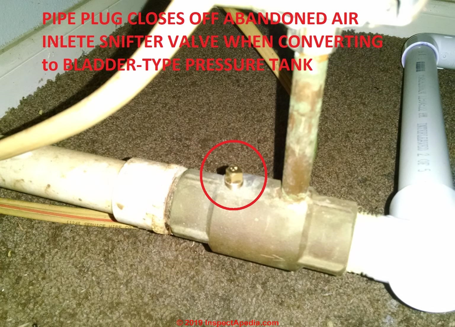 On 2020-02-16 - by (mod) - pipe plug seals abandoned snifter valve when changing to bladder-type pressure tank
Good going, Alan. That's probably going to be sufficient.
Thanks for the follow-up as that will help other readers.
On 2020-02-16 by Alan
As a follow up. I removed the snifter and plugged the hole. I'm not getting any air in the water supply now and that's without doing anything down hole. I hope it stays that way.
On 2019-01-14 by jeff
I've added a question. any thought
On 2019-01-14 by Jeff
hey there,
I have a cottage 100 ft from the wellhead, the waterline will be running downhill to the cottage. Then turn upwards to enter through the floor (built on sono tubes") I want to be able to use the cottage in the cold months.
My current plan is to bury a line from the pitless 4 feet down and cover it with 3" foam to the exterior wall of the house where the trenching stops.
ABS/Heat trace/foam up out of the trench to the floor through the 18" air space.
I dont want the heat trace running all winter for a few weeks use and I'm worried that if i shut it off it'll freeze solid and be a bugger to thaw the day we show up. any suggestions?
is there a was to easily drain this system with a 3ft belly in it. I considered installing a "t" to 1/4 turn valve and a few buckets of gravel 4 ft below grade a the low point. there is a snifter on the supply side of my pressure tank but nothing to break the vacume uphill at the well.
On 2016-11-27 by (mod) -
Johnny
There are two components: a air admittance valve above ground, usually near the water tank that admits air into the piping so that water can run out of it, and then a snifter valve or drainback valve in the well - above the water line.
On 2016-11-27 by Johnny
I have a back flow system on my well. When the well shuts off it appears no water runs back into the well. I put on a new snifter but no luck there.
It got down to 0 degrees and now when I turn on the pump, nothing happens, no water. I presume the line is now frozen.
Could it be the back flow valve in the well is plugged up? I am going to install heat tape on my line. The line comes out of the ground and is open to the atmosphere under my cabin for about 25'
On 2016-11-26 - by (mod) -
Ron:
If you replaced the in-well snifter valve and it's leaking I suspect silt or debris in the well water has fouled the valve - it's basically a tiny check valve.
If you replaced the above-ground snifter valve in what looks like a tire valve stem on your well piping at or near your water tank, perhaps the valve stem or core is defective and needs replacement, or it was not properly installed.
Also check with your well supplier: the valve stem core in a snifter valve usually operates at a lower pressure range than the identical-looking valve stem core that is used in automotive tires.
On 2016-11-26 14:56:12.862294 by Ron
My sniffer valve was leaking whenever the pump would run. I replaced the valve with a new valve and it still leaks when the pump runs. The temp. is around 60.
Question: snifter valve air volume control systems can remove iron and sulphur from water?
(Jan 22, 2014) joe said:
Hello I am writing about the snifter valve. If you read your article on why are snifter valve air volume control systems used one it states that the high absorption of air into the system helps oxidize and thus reduce hydrogen sulfide or perhaps iron. But in your last email to me you said it would not. So you have me confused. Thanks for your reply. JOE
Reply:
Thanks so much Joe, I will review these articles and fix that inconsistency.
Honestly, I am sure that I added the statement to which you refer while I was reviewing research about snifter valves, but in replying to your email I simply forgot about it.
You were right, I was mistaken. However we need some clarification:
A snifter valve is only used on deep wells that are operated by a submersible pump AND that feed water into an older-style bladderless expansion tank. The snifter valve, installed in the well piping lets air into the system at each pump on cycle.
A companion vent valve installed above ground, close to the pressure tank, or in some cases ON the pressure tank, vents excess air out of the tank to keep the tank's air charge at the proper level.
A water supply system that uses a "captive air" type water pressure tank that incorporates an internal bladder does not need this automatic injection of make-up air, so will not have a snifter valve. In fact when a plumber converts a water supply system from bladderless-tank to internal-bladder tank, s/he needs to also pull the well piping and remove the old snifter valve if one was installed.
That is what was going on in my photo series about snifter valves.
So if your water system uses a bladder type tank you wouldn't have a snifter valve installed.
Finally, and here is where we need to do more research, despite the claims of the snifter valve camp, I am doubtful that air injection ALONE will cure a serious sulphur odor in the water supply. More likely we'll need to install a treatment system such as a potassium permanganate "green sand as the plumbers call it" system or a chlorine injection system, combined with filtration, or some equivalent.
Do keep me posted, and thank you VERY much for helping me out with clarity and pointing out an inconsistency on this topic.
Question: to drain the water line I should open the cap on the snifter valve?
(Oct 13, 2014) Ray said:
I recently had a new well installed, drilled w/ a submergible pump. a internal bladder tank was installed .
I was concerned about the water in the tank and water line freezing in the winter , so a sniffer valve was installed on the the check valve.
I was told when shutting the system down for the winter, to open and drain the water tank, and to open the green valve cap on the sniffer/check valve to introduce sir to the system , that would allow the water in the line to drain back into the well. Will this advise work? is their any problem with the sniffer valve installed with an internal bladder water tank? thank You
Reply:
Yes there's a possibility that the advice you were given will work, Ray. But just removing a valve cap won't do it. That cap is supposed to be loose and able to admit air at all times. You shouldn't have to open the snifter valve (found on a check valve usually mounted at the bottom of the water pressure tank) as it should open to admit air on its own - at the end of a pump-on cycle.
If your snifter valve is not working it probably needs a replacement. If you're replacing just the valve stem core don't buy one at your auto parts store - those schrader valves and valve cores operate at different (higher) pressure ranges and are not designed for this application.
...
Continue reading at DRAIN BACK / SNIFTER VALVE CONVERSION to BLADDER-TYPE WATER TANK or select a topic from the closely-related articles below, or see the complete ARTICLE INDEX .
Or see these
Recommended Articles
- AIR DISCHARGE at FAUCETS, FIXTURES
- SNIFTER & DRAIN BACK VALVES
- DRAIN BACK / BLEED BACK VALVE / SNIFTER VALVE PURPOSES
- DRAIN BACK & SNIFTER VALVE SYSTEM COMPONENTS
- DRAIN BACK & SNIFTER VALVE OPERATION
- DRAIN BACK / SNIFTER VALVE TROUBLESHOOTING
- DRAIN BACK & SNIFTER VALVE INSTALLATION / REPLACEMENT
- DRAIN BACK / SNIFTER VALVE CONVERSION to BLADDER-TYPE WATER TANK
- DRAIN BACK / BLEED VALVE / SNIFTER VALVE SUPPLIERS
- MORRISON WELL SYSTEM FUNCTION & REPAIR
- WATER PUMP SHORT CYCLING - home
Suggested citation for this web page
DRAIN BACK & SNIFTER VALVE INSTALLATION / REPLACEMENT at InspectApedia.com - online encyclopedia of building & environmental inspection, testing, diagnosis, repair, & problem prevention advice.
Or see this
INDEX to RELATED ARTICLES: ARTICLE INDEX to WATER SUPPLY, PUMPS TANKS WELLS & SPRINGS
Or use the SEARCH BOX found below to Ask a Question or Search InspectApedia
Ask a Question or Search InspectApedia
Try the search box just below, or if you prefer, post a question or comment in the Comments box below and we will respond promptly.
Search the InspectApedia website
Note: appearance of your Comment below may be delayed: if your comment contains an image, photograph, web link, or text that looks to the software as if it might be a web link, your posting will appear after it has been approved by a moderator. Apologies for the delay.
Only one image can be added per comment but you can post as many comments, and therefore images, as you like.
You will not receive a notification when a response to your question has been posted.
Please bookmark this page to make it easy for you to check back for our response.
Our Comment Box is provided by Countable Web Productions countable.ca
Citations & References
In addition to any citations in the article above, a full list is available on request.
- [1] U.S. Gauge Special Application Gauges: Type 300L and 310WJ Air Volume Controls, product description, 2002, Ametek® Inc, U.S. Gauge, 820 Pennsylvania Blvd., Feasterville PA 19053, USA, Tel: 215-355-6900 www.ametekusg.com Customer Service: 863-534-1504, web search 03/23/2011, original source: http://www.jlwinstruments.com/PDF_files/D17_MODEL300-310.PDF Sadly this URL now reroutes to a dead end
- [2] AMTEK, 900 Clymer Avenue 8600 Somerset Drive Sellersville, PA 18960 U.S.A. or Customer Service at AMTEK, Largo, FL 33773 U.S.A.Sales/Technical Support: 215-257-6531, Customer Service: 727-536-7831, Website: www.amtekusg.com, Email US Gauge at usg.sales@ametek.com.
- [3] flosource.com/ provides links to some US Gauge air volume control products installation and adjustment
- Rasmussen Well Drilling, Inc. , 1793 Hwy 61, Two Harbors MN. Jeremy Rasmussen provides third generation well drilling and plumbing services on the North Shore of Lake Superior. Photos by DJF. Tel 218-834-3387. Email: rasmussenwell@frontier.com
- [5] Dill Air Controls Products, 1500 Williamsboro St., PO Box 159, Oxford, NC 27565, Tel: (919) 692‐2300, Website: http://dillaircontrols.com
- Smart Tank, Installation Instructions, Flexcon Industries, 300 Pond St., Randolph MA 02368, www.flexconind.com, Tel: 800-527-0030 - web search 07/24/2010, original source: http://www.flexconind.com/pdf/st_install.pdf [Copy on file as /water/Smart_Tank_Flexcon.pdf ] -
- Typical Deep Well Two Line Jet Pump Installation, Grove Electric, G&G Electric & Plumbing, 1900 NE 78th St., Suite 101, Vancouver WA 98665 www.grovelectric.com - web search -7/15/2010 original source: http://www.groverelectric.com/howto/38_Typical%20Jet%20Pump%20Installation.pdf, [Copy on file as /water/Jet_Pump_Grove_Elect.pdf ] - Cooperative Extension, School of Forest Resources, web search 07/24/2010, original source: http://pubs.cas.psu.edu/FreePubs/pdfs/XH0002.pdf
- In addition to citations & references found in this article, see the research citations given at the end of the related articles found at our suggested
CONTINUE READING or RECOMMENDED ARTICLES.
- Carson, Dunlop & Associates Ltd., 120 Carlton Street Suite 407, Toronto ON M5A 4K2. Tel: (416) 964-9415 1-800-268-7070 Email: info@carsondunlop.com. Alan Carson is a past president of ASHI, the American Society of Home Inspectors.
Thanks to Alan Carson and Bob Dunlop, for permission for InspectAPedia to use text excerpts from The HOME REFERENCE BOOK - the Encyclopedia of Homes and to use illustrations from The ILLUSTRATED HOME .
Carson Dunlop Associates provides extensive home inspection education and report writing material. In gratitude we provide links to tsome Carson Dunlop Associates products and services.
 | HOME | ABOUT | ASK a QUESTION | CONTACT | CONTENT USE POLICY | DESCRIPTION | POLICIES | PRIVACY | |
| © 2024 - 1985 Publisher InspectApedia.com - Daniel Friedman | |||||||||