
InspectAPedia® FREE Encyclopedia of Building & Environmental Construction, Diagnosis, Maintenance & Repair |
Question? Just ask us! InspectAPedia
|
 Single Line Jet Pumps & Water Wells, Explanation & Repairs

- POST a QUESTION or COMMENT about shallow wells and single line jet pumps: installation, plumbing, operation, diagnosis, repair
One-line jet pumps:
This article describes the components of a one-line jet pump water system, what the components look like, and what they do.
This article explains how a one-line jet pump works, where one line jet pumps are used, the pumping depth or lift height capacity of jet pumps, and jet pump installation, troubleshooting & repair procedures. We provide advice about what to do when things go wrong with your well pump.
InspectAPedia tolerates no conflicts of interest. We have no relationship with advertisers, products, or services discussed at this website.
What are the Components of a Shallow Well with a One Line Jet Pump?
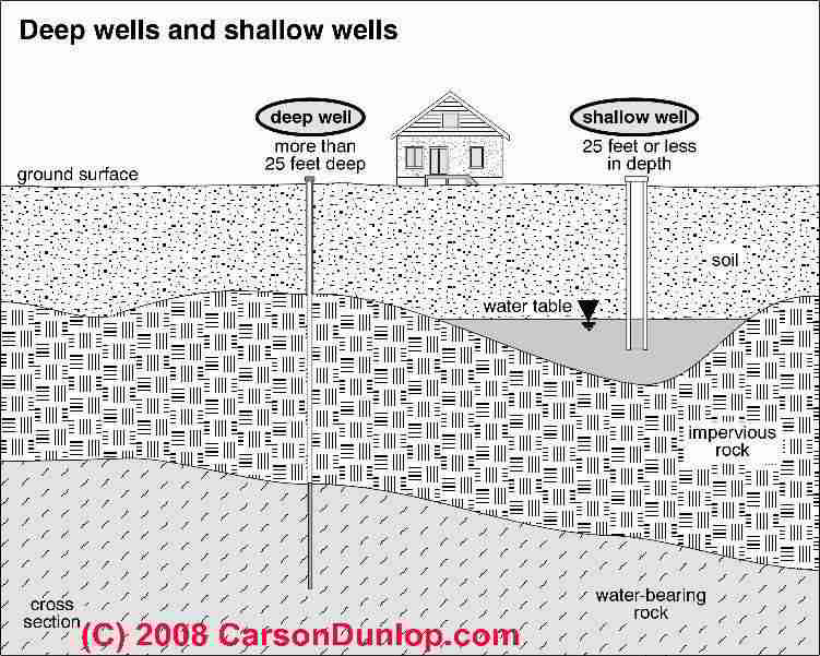
By definition, if a one-line jet pump is installed at a building, the well is a "shallow well", possibly a bored well or a hand dug well, or even a shallow drilled well. Here Carson Dunlop Associates sketch shows the difference between a 'deep well' and a 'shallow well'.
[Click to enlarge any image]
Refer also to our sketch just below where we depict a shallow well (less than 20 feet deep) served by a one-line jet pump located apart from the well.
A shallow well might be capable of delivering plenty of water, depending on just where it is located, but there are water quality concerns with shallow wells.
A shallow water well is more likely to receive surface runoff, making it a bit more at risk of contamination by bacteria or any chemical that might be on local ground surfaces such as road salt, fertilizers, or pesticides.
Most "shallow water wells" are less than 30 feet deep (so the foot valve is at 24-feet depth or less) and use an above-ground single-line jet pump to "suck" or draw water up from the well. These pumps cannot pull water from much deeper.
Water from deeper wells is delivered by a 2-line jet pump (also above ground) or a submersible in-well pump.
More about measuring the actual depth of a well is
at DEPTH of a WELL, HOW TO MEASURE.
An Explanation of the Parts of a Shallow Water Well

The following list and definition of water well parts and terms is organized from the top of our rough drawing towards its bottom and uses names that correspond to those shown in our ugly drawing.
The nicer drawing of a one line jet pump is provided courtesy of Carson Dunlop Associates and provides additional details about single line shallow well jet pump water systems
First we describe items listed on the right side of our sketch, second we describe items and terms listed on the left side of the sketch.

Buried well casing which is typical for older shallow wells - the well casing top may be above ground, buried and hidden from view entirely, or (luckily) located inside of a well pit (less common).
It is particularly important that the well cap on the casing be water tight
since otherwise unsanitary surface water and
debris can enter the well casing.
Many well caps are not water tight, which is why modern drilled well casings extend above ground level.
Where Else are One Line Jet Pumps Used?
A one line jet pump might also be installed to draw water from other shallow water supply sources including a
hand dug well
discussed at DUG WELLS, by HAND
or
a cistern discussed at CISTERNS, WATER STORAGE,
or
a spring which includes a spring box or a spring water collection pit
discussed at SPRINGS as WATER SUPPLY.
What is a One Line Jet Pump?

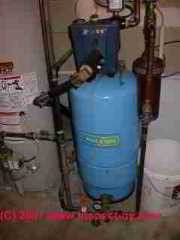
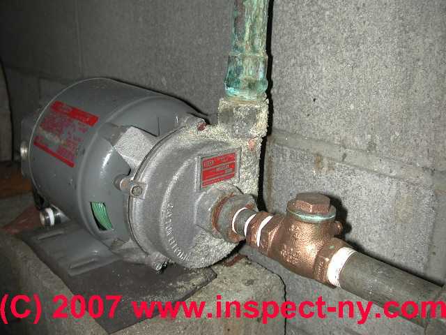
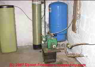
- A "one-line" jet pump is shown outside of the well, either inside of the building such as the blue water pump in our page top photo or like this green one line jet pump [Image] or perhaps in a well pit or well house.
"One line" refers to the fact that a single pipe connects the pump intake to the well, and the pump has to lift water out of the well and into the building it serves. If your well pump won't start
see ELECTRIC MOTOR OVERLOAD RESET SWITCH for some electric motor or pump motor troubleshooting suggestions.
Since the lift capacity of a one-line jet pump is limited to about 27' (usually 25 feet or less) you can bet that where you find this type of pump installed it is drawing from a shallow water well.
Our sketch shows the water pump connected to a water pressure tank which in turn supplies water to the building. The pressure tank is usually located very close to the jet pump but it could be elsewhere. - Pitless Adapter is the special fitting that seals the hole in the well casing where the water piping makes its right angled turn and then
exits the well casing to pass on to the building.
See WELL PIPING PITLESS ADAPTERS - Water piping to the house rises vertically inside the well casing from the top of the foot valve (see below) to a point (below the frost line in
cold climates) where it makes a right angled turn and passes out through the well casing and onwards to the water pump and pressure tank.
See WELL PIPING LEAK DIAGNOSIS - Well casing is in this sketch the 6-inch diameter steel pipe which is driven into the well from above ground into bedrock, then sealed against
groundwater leaks.
See WELL CASING LEAK REPAIRS
See WELL CAPS & COVERS for well casing cap sealing and venting requirements - Foot Valve is a one way or anti-siphon valve which is installed on the pick-up end of the water pipe near the bottom of the well.
The foot valve prevents water from flowing backwards out of the jet pump and well piping back into the well when the jet pump stops operating.
See WELL PIPING FOOT VALVE for details about this component.
You can see Carson Dunlop Associates' sketch of a foot valve HERE[Image].
If the foot valve is leaky and water runs back into the well we increase the wear on the water pump as it has to run more often, and pretty soon the water pump will lose its prime (water inside the pump mechanism) and it may be unable to retrieve any more water from the well whatsoever.
When a shallow well appears to have "run dry" one of the first things to check is whether or not the foot valve needs to be replaced. - Foot Valve Clearance from Bottom shows that the well piping and foot valve are inserted into the well some distance from the very bottom of
the well (inches to a few feet). We need this clearance to reduce the tendency of the well pump to pick up mud and debris from the bottom of the well.
See WELL PIPING FOOT VALVE - Static head shown in this sketch is the height of the column of water inside of the well between the bottom of the foot valve and the
top of the water when the well is at rest.
See WELL DYNAMIC HEAD & STATIC HEAD DEFINITION
We discuss "static head" and well recovery rates in detail
at WELL FLOW RATE More about measuring the actual depth of a well is
at DEPTH of a WELL, HOW TO MEASURE. - See WATER PUMP, ONE LINE JET OPERATION for a description of the operating sequence and controls on a one line jet pump water system.
Air Vents on Well Casings
Reader Question: Describe the Air Vent Piping on Shallow Wells
I have a shallow well about 5 feet from my house under my deck. The pipe bringing in the water goes through a hole in the basement cinder block into a crawl space, then about 30 feet to the pump and all the connections. Through the same hole in the cinder block enters another pipe about 1 inch in diameter. This pipe protrudes into the basement about 1 foot.
During the heavy rains of Hurricane Irene, water was flowing through this smaller pipe into our basement, so I stuffed a rag into it.
Could this be a vent pipe? and the groundwater was so full that it filled the well air pocket and flowed through the pipe? Should I open the well lid and re-direct the vent pipe? Can I keep the rag stuffed in the pipe?
None of the local plumbers did a good job installing years ago and we did not keep in touch with any of them. That’s why I am asking you. - P.H.
Reply: small diameter air intake vents are needed on air-tight shallow well casings
 A competent onsite inspection by a well plumbing expert usually finds additional clues that help accurately identify strange pipes or if necessary, diagnose a problem.
That said:
A competent onsite inspection by a well plumbing expert usually finds additional clues that help accurately identify strange pipes or if necessary, diagnose a problem.
That said:
if the second smaller diameter pipe is indeed connected to your well casing or casing top, as is often the case, it is very likely an air vent.
In shallow wells it was common practice to include a vent line to allow air to enter the well casing during water draw-down in the well, in order to avoid the flow resistance that the above-ground shallow-well pump would encounter if a vacuum was formed in the well casing by the falling water level.
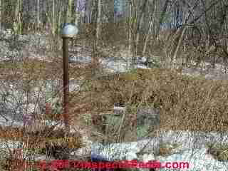
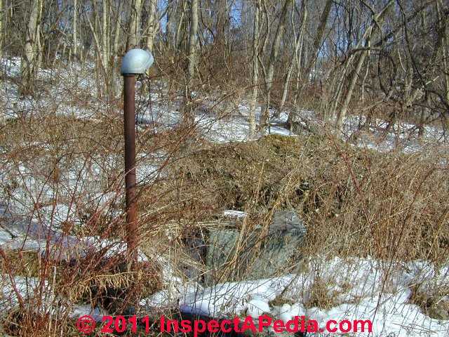
Our well casing top photo (left) includes a red arrow pointing to the NPT pipe thread that marks the location where an air vent tube would have been connected had one been in use on this well.
The two larger-diameter galvanized iron pipes and pipe caps protruding through the center of this well cap would have been used to connect the two lines of a two-line jet pump.
So this is not exactly your case, but our photo shows where the air vent connects at a well casing top.
Shallow well single line jet pumps can pull up water from a maximum of about 25 feet, so you can see that with these less powerful pumps you'd want to relieve the vacuum.
It's also plausible that during hurricane and storm flooding ground around your well may have been so saturated as to temporarily convert your well to function as an artesian well - delivering water on its own.
You can follow the pipe you asked about back to the well to confirm its connection and location and thus its use.
 Details about well casing air vent tubes and pipes
Finally, 1" is a bit bigger for a well vent than what I've usually encountered. Often the vent line is a simple flexible copper tube of 1/2" in diameter..
Well casing vent pipes are usually routed to a secure, clean indoor location in order to reduce the chances of well contamination from surface water entry into the casing through the vent.
On occasion we've seen copper tubing break off at the top of a well casing, admitting surface runoff and contaminating the well. We've also found an occasional crimped or clogged vent tube on a well casing.
The result of that problem can be reduced water delivery rate from the well - the jet pump is pulling water against a vacuum.
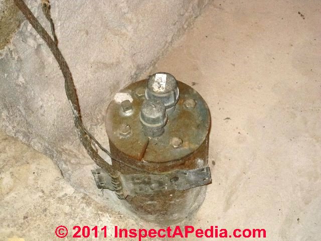
But on some wells we may find a larger diameter well casing vent pipe installed as a standpipe that looks something like our photo at left
What is the Pumping Capacity in Gallons per Minute for a 1-Line Shallow Well Jet Pump?
A one-line jet pump can typically raise water from depths of just a few feet (or "0" depth) to about 25 feet in depth, and at water delivery rates of 4 gpm up to as much as 25 gpm depending on the variables we list below the well pump capacity tables shown.
At WATER PUMP CAPACITIES TYPES RATES GPM we compare the pumping capacities of one line jet pumps, two line jet pumps, submersible well pumps, and other water pumping methods.
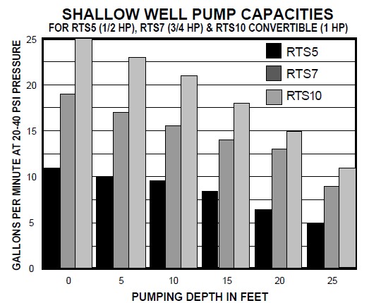
A nice example table of shallow well 1-Line Jet Pump Capacities for 1/2 hp, 3/4, and 1 hp shallow well pumps is provided in the Water Ace Jet Pump Installation Manual and excerpted below to illustrate the factors that determine well pump capacity.
Both of the charts below are for one-line jet pumps produced by Water Ace. 1-Line jet pumps intended for shallow well use and made by other manufacturers can be expected to have similar capacities.
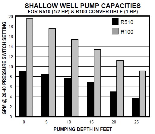
The Water Ace charts (shown in part above) make clear that the capacity of a one-line shallow well jet pump to deliver water at a given flow rate varies by these factors:
- the depth of the well (the bottom scale in the two charts)
- the pump horsepower (the color codes indicate pump model and horsepower HP variation)
- The well pump model (the right hand table is for the company's more powerful well pump series of 2-line jet pumps)
- The condition of well piping, including pipe diameter, length, number of bends or elbows
- The presumption that the entire piping system has no leaks
Permission requested, Water Ace Corp. Aug 2010 - Pentair Pump Group.
Watch Out: Safety warnings are throughout any pump manufacturer's instructions. Because some pump models are capable of developing internal pressures of more than 100 psi, if your building piping, pressure relief valves, safety controls, wiring, and plumbing are not properly installed, very dangerous conditions including electrical shock, tank explosion, and leaks or floods can occur.
1-Line Water Pump Manuals
See our complete library of pump manuals found at WATER PUMP & TANK I&O & REPAIR MANUALS
Some typical examples are given below.
- Access Water Energy, PO Box 2061, Moorabbin, VIC 3189, Australia, Tel: 1300 797 758, email: sales@accesswater.com.au Moorabbin Office: Kingston Trade Centre, 100 Cochranes Rd, Moorabbin, VIC 3189 Australia, Web: http://www.accesswater.com.au/
Australian supplier of: Greywater systems, Solar power to grid packages, Edwards solar systems, Vulcan compact solar systems, water & solar system pumps & controls, - Grove Electric, Typical Shallow Well ONE LINE JET PUMP INSTALLATION [PDF], Grove Electric, G&G Electric & Plumbing, 1900 NE 78th St., Suite 101, Vancouver WA 98665 www.grovelectric.com - web search -7/15/2010 original source: http://www.groverelectric.com/howto/38_Typical%20Jet%20Pump%20Installation.pdf
This page has illustrations and description of a typical shallow well one line jet pump installation. - Water Ace JET PUMP INSTALLATION MANUAL #1, instructions from Water Ace Pump Co., Web: http://www.waterace.com/ - 08/28/2010, original source: http://www.waterace.com/pdf/R510%20R520%20and%20R100%20Jet%20Pumps%20Manual.pdf
Consumer hotline: 800-942-3343 - instructions for the installation and maintenance of
Water Ace shallow well pump Model R510 1/2 HP
Water Ace deep well pump Model R100 convertible 1HP and
Water Ace deep well jet pump Model R250 convertible 1/2 hp.
Quoting from the company's website:
The Water Ace Pump Company... offer a complete line of sump, sewage, lawn sprinkler, swimming pool, submersible well and jet pumps as well as pressure tanks and accessories. - Water Ace JET PUMP INSTALLATION MANUAL #2 Water Ace Pump Co., web search 08/28/2010, original source: http://www.waterace.com/pdf/RTS5%20RTS7%20RTS10%20RC5%20and%20RC10%20Jet%20Pumps%20Manual.pdf
Water Ace Shallow Well 1-line Jet Pump Models RTS5 (1/2HP), Model RTS7 (3/4 HP) and RTS10 (1HP)
...
Continue reading at WATER PUMP, ONE LINE JET OPERATION or select a topic from the closely-related articles below, or see the complete ARTICLE INDEX.
Or see WATER PUMP, ONE LINE JET FAQs - questions & answers about single line jet pumps posted originally on this page
Or see these
Recommended Articles
- AIR DISCHARGE at FAUCETS, FIXTURES
- NO WATER PRESSURE - no water at all
- SHORT CYCLING WATER PUMP - pump keeps turning on and off rapidly
- VARIABLE FREQUENCY / VARIABLE SPEED DRIVE WELL PUMPS (VFDs)
- WATER PRESSURE LOSS DIAGNOSIS & REPAIR - home
- WATER PUMP CONTROLS & SWITCHES - home
- WATER PUMP DIAGNOSTIC TABLE
- WATER PUMP INTERMITTENT CYCLING - pump cycles on and off at odd times or for no apparent reason
- WATER PUMP, ONE LINE JET
- WATER PUMP PRESSURE SWITCH MANUALS
- WATER PUMP PRIMING PROCEDURE - prime the pump using a garden hose or by other means
- WATER PUMP PROTECTION SWITCH
- WATER PUMP, SUBMERSIBLE
- WATER PUMP WONT STOP RUNNING - pump runs continuously, never shuts off or can't reach shut-off pressure
- WATER PUMP CONTROLS & SWITCHES - home
- WATER PUMP REPAIR GUIDE - home
- WATER PUMP, ONE LINE JET
- WATER PUMP, TWO LINE JET
- WATER TANK: USES, TROUBLESHOOTING
- WATER PUMP & TANK I&O & REPAIR MANUALS - manuals for water pump controls, pumps, tanks
- WATER PRESSURE INTERMITTENT LOSS - occasional loss of water pressure
- WELL PIPING CHECK VALVES
- WELL PUMP PRIMING PROCEDURE if you need to re-prime your jet pump.
- WELL CAPS & COVERS - requirements for sealed well caps & covers, requirements for vents & exclusion of vent requirements for some jet pump installations.
- WELL PIPING TAIL PIECE
- WELL WATER PRESSURE DIAGNOSIS
Suggested citation for this web page
WATER PUMP, ONE LINE JET at InspectApedia.com - online encyclopedia of building & environmental inspection, testing, diagnosis, repair, & problem prevention advice.
Or see this
INDEX to RELATED ARTICLES: ARTICLE INDEX to WATER SUPPLY, PUMPS TANKS WELLS
Or use the SEARCH BOX found below to Ask a Question or Search InspectApedia
Ask a Question or Search InspectApedia
Try the search box just below, or if you prefer, post a question or comment in the Comments box below and we will respond promptly.
Search the InspectApedia website
Note: appearance of your Comment below may be delayed: if your comment contains an image, photograph, web link, or text that looks to the software as if it might be a web link, your posting will appear after it has been approved by a moderator. Apologies for the delay.
Only one image can be added per comment but you can post as many comments, and therefore images, as you like.
You will not receive a notification when a response to your question has been posted.
Please bookmark this page to make it easy for you to check back for our response.
Our Comment Box is provided by Countable Web Productions countable.ca
Citations & References
In addition to any citations in the article above, a full list is available on request.
- Penn State, Water Fact Sheet #3, USING LOW-YIELD WELLS [PDF], Penn State College of Agricultural Sciences, Cooperative Extension, School of Forest Resources, web search 07/24/2010, original source: http://pubs.cas.psu.edu/FreePubs/pdfs/XH0002.pdf
- Flexcon, SMART TANK INSTALLATION INSTRUCTIONS [PDF], Flexcon Industries, 300 Pond St., Randolph MA 02368, www.flexconind.com, Tel: 800-527-0030 - web search 07/24/2010, original source: http://www.flexconind.com/pdf/st_install.pdf
- Grove Electric, Typical Shallow Well One Line Jet Pump Installation [PDF], Grove Electric, G&G Electric & Plumbing, 1900 NE 78th St., Suite 101, Vancouver WA 98665 www.grovelectric.com - web search -7/15/2010 original source: http://www.groverelectric.com/howto/38_Typical%20Jet%20Pump%20Installation.pdf
- Grove Electric, Typical Deep Well Two Line Jet Pump Installation [PDF], Grove Electric, G&G Electric & Plumbing, 1900 NE 78th St., Suite 101, Vancouver WA 98665 www.grovelectric.com - web search -7/15/2010 original source: http://www.groverelectric.com/howto/38_Typical%20Jet%20Pump%20Installation.pdf
- Our recommended books about building & mechanical systems design, inspection, problem diagnosis, and repair, and about indoor environment and IAQ testing, diagnosis, and cleanup are at the InspectAPedia Bookstore. Also see our Book Reviews - InspectAPedia.
- In addition to citations & references found in this article, see the research citations given at the end of the related articles found at our suggested
CONTINUE READING or RECOMMENDED ARTICLES.
- Carson, Dunlop & Associates Ltd., 120 Carlton Street Suite 407, Toronto ON M5A 4K2. Tel: (416) 964-9415 1-800-268-7070 Email: info@carsondunlop.com. Alan Carson is a past president of ASHI, the American Society of Home Inspectors.
Thanks to Alan Carson and Bob Dunlop, for permission for InspectAPedia to use text excerpts from The HOME REFERENCE BOOK - the Encyclopedia of Homes and to use illustrations from The ILLUSTRATED HOME .
Carson Dunlop Associates provides extensive home inspection education and report writing material. In gratitude we provide links to tsome Carson Dunlop Associates products and services.
 | HOME | ABOUT | ASK a QUESTION | CONTACT | CONTENT USE POLICY | DESCRIPTION | POLICIES | PRIVACY | |
| © 2024 - 1985 Publisher InspectApedia.com - Daniel Friedman | |||||||||