
InspectAPedia® FREE Encyclopedia of Building & Environmental Construction, Diagnosis, Maintenance & Repair |
Question? Just ask us! InspectAPedia
|
 Two Line Jet Pumps for Water Wells
Jet Pump Installation & Repair
- POST a QUESTION or COMMENT about 2-line jet pumps on water wells
Guide to 2-line jet pumps on water wells: What is a two-line jet pump? What do the two pipes do? How does a jet pump work?
This article describes the components of a two-line jet pump water system, what the components look like, and what they do.
We discuss how two-line jet pumps are selected, installed, jet pump troubleshooting, & repair procedures. We also describe the components of a two line jet pump water supply system.
What types of wells use a two-line jet pump for water delivery. From what depth can a two line jet pump deliver water? Types of wells and water supply systems and what to watch out for with each. Well pump & water tank diagnosis & repair procedures. Electric pump motor troubleshooting guide - table of problems & solutions.
InspectAPedia tolerates no conflicts of interest. We have no relationship with advertisers, products, or services discussed at this website.
Components of a Well with a Two Line Jet Pump?
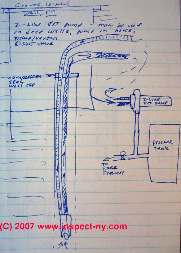
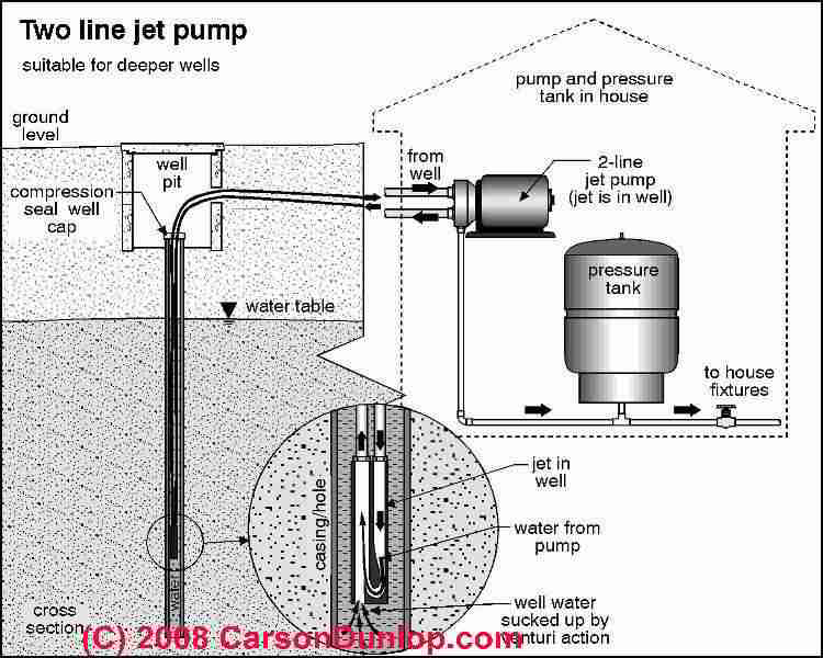 Refer to the illustration above right, courtesy of Carson Dunlop Associates and also to our rough sketch provided below to see the components providing well water to a building served by a two-line jet pump located apart from the well.
In our drawing the two line jet pump which draws water from the well and the water pressure tank are shown located separately from the well itself, and the well and its casing are shown located inside of a well pit.
The actual lift capacity will vary depending on the pump horsepower and other factors such as piping length, bends, diameter. Common lift height is about 30 to 80 feet but some deeper installations work.
For example, a twin pipe jet pump plumbing arrangement requires [typical specifications]
- A well bore of 4" in diameter or larger - regardless of the well's flow-rate we need enough space for the piping, well jet, and other components.
- A 1 1/4" diameter suction line
- A 1" diameter drive line (this is the line down which water is pumped to bring more water back up by sending the drive line water through a water pick-up venturi device in the well)
- A 4" or 5" well jet - the venturi device that picks up water from the well bore in a 2-line jet pump system.
- A foot valve on the bottom of the jet assembly or on the end of a 34" tailpiece to avoid loss of prime. The tailpiece avoids over-pumping if the well flow rate is less than the pumping rate.
Well pits
such as the one we've drawn are used especially in climates exposed to freezing weather, as a way to get access to the well casing and well piping and to route well piping out of the well through the top of the well casing and on to the building while protecting it from freezing.
In addition to showing a well pit in this sketch, we discuss and illustrate well pits a bit more
at WELL PITS
A more modern device, the pitless adapter which permits a water tight piping connection out through the side of the well casing is shown in our sketch
at DRILLED WELLS, STEEL CASINGS
For help priming your jet pump see WATER PUMP PRIMING PROCEDURE
What is the Pumping Capacity in Gallons per Minute for a 2-Line Deep Well Jet Pump?
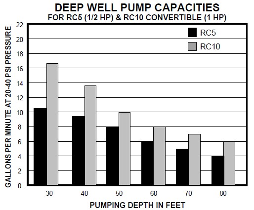
 A two-line jet pump can typically raise water from depths of 30-feet to 80-feet, and at water delivery rates of 4 gpm (gallons per minute) (for a 1/2 hp 2-line jet pump serving an 80 foot deep well) to 16 gpm (for a 1 hp 2-line jet pump serving a 30 foot deep well).
At WATER PUMP CAPACITIES TYPES RATES GPM we compare the pumping capacities of one line jet pumps, two line jet pumps, submersible well pumps, and other water pumping methods.
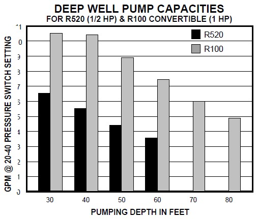
A nice example table of Deep Well 2-Line Jet Pump Capacities for 1/2 hp and 1 hp deep well pumps is provided in the Water Ace Jet Pump Installation Manual and excerpted below to illustrate the factors that determine well pump capacity.
Both of the charts below are for 2-line jet pumps produced by Water Ace. 2-Line jet pumps intended for deep well use and made by other manufacturers can be expected to have similar capacities.
Factors Affecting Actual Water Pump Capacity
The Water Ace charts (shown in part above) make clear that the capacity of a deep well pump to deliver water at a given flow rate varies by these factors:
- The depth of the well (the bottom scale in the two charts)
- The pump horsepower (the color codes indicate pump model and horsepower HP variation)
- The well pump model (the right hand table is for the company's more powerful well pump series of 2-line jet pumps)
- The condition of well piping, including pipe diameter, length, number of bends or elbows
- The presumption that the entire piping system has no leaks
Permission requested, Water Ace Corp. Aug 2010 - Pentair Pump Group.
Watch Out: Safety warnings are throughout any pump manufacturer's instructions.
Because some pump models are capable of developing internal pressures of more than 100 psi, if your building piping, pressure relief valves, safety controls, wiring, and plumbing are not properly installed, very dangerous conditions including electrical shock, tank explosion, and leaks or floods can occur.
How a Two-Line Jet Pump Works to Get Water Out of the Well
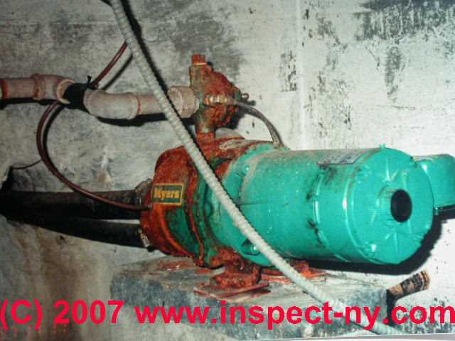
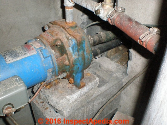
A two line jet pump refers to the observation that two pipes are connected between the jet pump and the well. In our photo at left you can see the two black plastic lines leaving the front of the water pump.
A two line jet pump draws water out of the well by magic: it forces water away from the pump and into the bottom of the well through one of the pipes (usually the smaller diameter pipe).
At the bottom of the well water from the jet pump is forced through a venturi device (a sort of funnel shaped opening) and then back upwards into the larger diameter pipe. Water flowing through the venturi device at the bottom of the well piping draws still additional water out of the well and into the larger diameter pipe that flows back to the building.
The requirement to have some water to send down to the well in order to bring a larger quantity of water back is why a two line jet pump can't provide any water or water pressure in a building if it loses its prime.
See WELL PUMP PRIMING PROCEDURE if you need to re-prime your jet pump.
In our sketch above see the two arrows showing water entering the bottom of the piping.
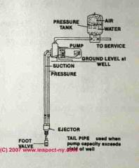
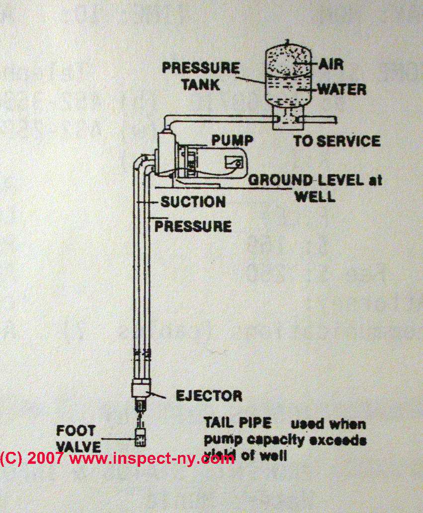
The following list and definition of two-line deep well jet pump and water well parts and terms is organized from the top of the drawing towards its bottom and uses names that correspond to those shown in our ugly sketch above.
- A pair of well pipes
leave the well casing through a water-tight cap on top of the casing and are connected to the appropriate fittings on the two line jet pump which is (probably) located in the building it serves.
The well casing top in this example is located inside of a well pit but it could be simply buried in the soil. It is particularly important that the well cap on the casing be water tight since otherwise unsanitary surface water and debris can enter the well casing.
Many well caps are not water tight, which is why modern drilled well casings extend above ground level. - Compression Seal Well Cap
is a special well cap with openings to permit passage of the two water lines (and maybe an air vent tube) out of the well to above ground.
A compression seal well cap consists of steel top and bottom plates which "sandwich" rubber fittings which surround the water piping.
As the two plates are bolted together they squeeze the rubber "sandwich" gaskets causing them to expand and seal both around the water piping and inside the diameter of the well casing.
See WELL CAPS & COVERS for well casing cap sealing & venting requirements - A "two-line" jet pump (for the example in our sketch and the subject of this page)
is shown outside of the well, either inside of the building or perhaps in a well pit or well house. "Two line" refers to the fact that two water pipes connect the pump to the well.
Since the lift capacity of a two-line jet pump is not limited to the shallow-well depth of 27' chances are that where you find a two line jet pump installed it is drawing from a deep water well. Our sketch shows the pump connected to a water pressure tank which in turn supplies water to the building.
The pressure tank is usually located very close to the jet pump but it could be elsewhere.
Your pump could be a 1-line jet pump (also outside the well) or a submersible (in-well) pump - all of which are discussed in detail in this article series. - Well Jet and Well Piping Foot Valve
is a venturi device through which the two line jet pump sends water to collect and bring still more water back into the building.
See WELL PIPING FOOT VALVES for details.
You can see Carson Dunlop Associates' sketch of a foot valve HERE [Image] and also at the end of this list. - Well Piping Tail Piece
some wells may contain a tailpiece at the end of the well piping - a device designed to prevent jet pump damage if well water falls too low. If well water drops to an unsafe level the tailpiece recirculates water to keep the pump from running dry.
See WELL PIPING TAIL PIECE - Well Jet & Foot Valve Clearance from Well Bottom
(not shown) means that the well piping, bottom venturi, and foot valve are inserted into the well some distance from the very bottom of the well (inches to a few feet). We need this clearance to reduce the tendency of the well pump to pick up mud and debris from the bottom of the well. - Static head
(not shown in this sketch) is the height of the column of water inside of the well between the bottom of the foot valve and the top of the water when the well is at rest. We discuss "static head" and well recovery rates in detail
at WELL FLOW RATE
What is the Well Piping Foot Valve used in a well and what goes wrong with foot valves?

If you keep losing prime at the water pump where a two-line jet pump is installed,
it's probable that a check valve at the pump or more likely at the FOOT VALVE in the bottom of the well needs to be replaced.
See WELL PIPING FOOT VALVES for details about this component.
Carson Dunlop Associates' sketch at left shows how a foot valve works and where it is installed. Replacing a foot valve in the well requires that the well be opened and the well piping be pulled out to permit removal of the old valve and installation of a new one.
After replacing the foot valve you should shock the well since you've probably contaminated it by laying your well piping and parts on the ground (and foot valves at the plumbing supplier are not kept in sterile containers).
We discuss how to shock a well at WELL SHOCK / CHLORINATION PROCEDURE our WELL SHOCKING GUIDE
2-Line Jet Pump Well Pump Diagnostic Tables
- 2-LINE JET PUMP RUNS but NO WATER or WEAK WATER PRESSURE - no water at all or water pressure (flow rate) is poor
- 2-LINE JET PUMP WON'T STOP - RUNS CONTINUOUSLY or TOO OFTEN - pump keeps on running or cycles on and off frequently
- 2-LINE JET PUMP WON'T TURN ON - pump won't start
- 2-LINE JET PUMP STARTS, OVERHEATS, TRIPS RESET BUTTON - pump shuts itself off
- 2-LINE JET PUMP PIPING CONNECTIONS - signs of trouble with the well or pump piping & pipe connections
What to do if the well pump runs But you Have NO Water or POOR Water Pressure |
||
| Well Pump Motor Runs but no Water is Delivered | If no water is being delivered at all the problem could be loss of water in the well or the well pump may have lost prime. | Shut off the pump. Wait at least half an hour to let the pump motor cool. Wait 1-3 hours or longer if your well is marginal and may have run dry. Then see WELL PUMP PRIMING PROCEDURE For a complete diagnostic checklist for well pumps |
| Well Pump Motor Keeps Running & Won't Stop | If the pump won't turn off the cause may be a damaged pump control, a plumbing or fixture leak, or a well problem. | Watch out: If the pump motor won't shut off you should turn off electrical power to the pump to avoid damaging it, then diagnose the problem. |
| Water pump runs but water pressure is weak | If the pump runs and turns on and off normally but water pressure is poor the problem could be poor water flow into the well, a well piping leak, a damaged pump, or a few other things. | For diagnosis See WATER PRESSURE TABLE 2: PUMP RUNS, WEAK or NO WATER PRESSURE |
What to do if the well pump runs continuously or runs too often |
||
| If the Well Pump Motor Runs Too Often | If the pump runs too often the cause may be a control problem, water tank problem, piping problem, or a well problem. | See INTERMITTENT CYCLING WATER PUMPS if the pump runs at odd times for no apparent reason. See WATER PUMP SHORT CYCLING CAUSES if the pump is turning on and off too frequently. |
| If the Well Pump Motor Keeps Running & Won't Stop | If the pump won't turn off the cause may be a damaged pump control, a plumbing or fixture leak, or a well problem. | Watch out: If the pump motor won't shut off you should turn off electrical power to the pump to avoid damaging it, then diagnose the problem. |
This article series describes various types of drinking water sources like wells, cisterns, dug wells, drilled wells, artesian wells and well and water pump equipment. We provide advice about what to do when things go wrong.
Things to Check if the Well Pump Will Not Start |
||
|---|---|---|
| Pump Trouble Cause | Diagnostic Procedure | Repair Procedure |
| Blown fuse, tripped breaker | Replace fuse or breaker - does the pump run and keep running normally? | Be sure proper breaker or fuse size in ampacity is installed |
| Low voltage to the pump | Check with VOM at the pressure control switch or at the pump wiring | Be sure the proper size of wire is used for the ampacity and length of circuit; Test for low voltage to the building. |
| Loose or broken pump wire | Check wiring against the pump installation manual diagram, check all connections for tightness, shorts, burns, damage | Rewire or repair or replace wiring |
| Burned out pump motor | Check that the pump pressure control switch is trying to turn on the pump and that there is voltage at the pump wiring | Repair or replace the pump motor |
| Bad pump pressure control switch | Check the switch contacts for burning or wear | Adjust or replace the pressure control switch. Temporary emergency repair by cleaning the switch contacts may be possible. |
| Bad pump pressure control switch | Check the tubing connecting the pressure switch to the pump housing for clogging | Clean or replace the tubing and be sure the connections are not leaky - an air leak will prevent the switch from sensing pressure properly |
| Bad pump impeller or impeller seal leak | Turn off electric power to pump, see if you can move the impeller or motor - if it won't turn it is jammed or damaged | Remove obstruction in impeller housing, inspect for and replace damaged impeller or frozen motor. |
| Bad pump motor starting capacitor | Use a VOM in ohms setting to check resistance across the capacitor. If the meter does not move (no current flows) the capacitor is "open". If there is zero resistance the capacitor is shorted. | Replace the starting capacitor |
| Pump motor shorted out, jammed, burned up | Fuse blows or breaker trips as soon as the pump tries to turn on. If the external wiring is ok (no short circuits) the motor is shorted internally | Replace the pump motor |
Notes to the table above
- Some of the well pump troubleshooting suggestions in this list can be found at the Betta-Flo Jet Pump Installation Manual from the National Pump Co. given at References or Citations .
- Canada, Alberta, DEEP WELL JET PUMPS [PDF] Alberta Agriculture and Rural Development, Alberta Ag-Info Centre Call toll-free: 310-FARM (3276) Website:www.agriculture.ablerta.ca - retrieved 2022/09/05 original source: https://www1.agric.gov.ab.ca/
- See also WATER PUMP & TANK I&O & REPAIR MANUALS
Things to Check if the Pump Motor Starts but Overheats and Trips its Reset Button |
||
| See ELECTRIC MOTOR OVERLOAD RESET SWITCH for how to find and reset this button | ||
| Bad line voltage | Use a VOM to check the voltage level at the pressure control switch | If voltage is too low, check voltage at the electrical panel and check that the proper size wiring was used for the ampacity and length of run and that there are no partial shorts or damaged wires or connectors |
| Incorrect motor wiring | Check the actual electrical wiring against the motor wiring diagram or the installation manual for the equipment | Reconnect wiring properly |
| Motor is too hot due to surroundings - inadequate ventilation | Check the air temperature where the motor is located. If the air temperature is over 100 degF, the pump may be too hot and its thermal overload switch tripping because of the environment, not a pump problem. | Install adequate ventilation, or if needed, shading, or relocate the motor/equipment to a cool location |
| Pump operates too long at low water pressure | If the well recovery rate is too poor and the pump is operating at low water pressure, possibly because a tailpiece is installed to prevent air injection and pump burnup, the pump may be overheating. | Install a valve on the water discharge line and reduce water flow to increase water pressure inside the pump itself. |
- Grove Electric, Typical Deep Well TWO LINE JET PUMP INSTALLATION [PDF], Grove Electric, G&G Electric & Plumbing, 1900 NE 78th St., Suite 101, Vancouver WA 98665 www.grovelectric.com - web search -7/15/2010 original source: http://www.groverelectric.com/howto/38_Typical%20Jet%20Pump%20Installation.pdf
This page has illustrations and description of a typical two line jet pump installation for deep wells.
Jet Pump Conversions & Piping Connections
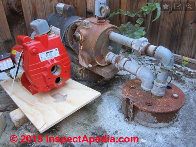
Reader Question: how do I connect mis-aligned 2-line jet pump openings to the well piping?
27 April 2015 Alex said:
I am planning on replacing my very old well pump, but I realized that my new pump has the larger diameter pipe coming into the top, whereas the old pump had the larger diameter pipe on the bottom. Is it always the case that the larger diameter pipe is the suction line?
Any tips on how I should plumb it? I don't have the space to plumb in on the opposite side of the well from where the current pump sits. Is it acceptable to use flex line, or should I stick with rigid (copper or brass)?
[Click to enlarge any image]
Reply: piping connections for a Red Lion RJC-100 convertible 2-line jet pump
Yes the larger diameter pipe opening on a 2-line jet pump is the suction line. You can tell me the brand and model of pump and we ought to be able to find the pump specifications and installation manual that will make that clear if you're missing those documents.
27 April 2015 Alex said:
Thanks DanJoeFriedman.
My new pump is a Red Lion RJC-100. I have the manual. I was just confused by the fact that the old pump had the suction and the pressure holes opposite of how my new pump is configured. In order to install this new pump, I think I'm going to have to rotate the cap 180 degrees.
The way it's oriented now, the larger diameter pipe (suction) is directly in front of the pressure pipe, so I'm not able to plumb it without getting really creative. Hard to explain, but I'll try to post another photo. Hopefully one of these works.
Reply:
Alex,
I took a look at your photo and will add it in this article above as well so that other readers may offer a suggestion (let me know if you do not want that action).
The face openings on the new Red Lion RJC-100 cannot be rotated, and indeed the inlet and outlet openings are reversed in position from your old pump.
If you want to use the new unit I suggest giving yourself adequate working space to make the necessary connections by moving the location of the new pump to one side - more or less as you have it positioned now, or elevating it a foot if needed as well.
By removing the union and street-elbow at the well top and starting there you can make the necessary routing changes, routing the jet pump inlet and outlet lines to their destinations. It'll take a two more elbows but is do-able.
Before doing that, however I'd give the company's tech support a call or email to ask if in fact the face of the pump can in fact be rotated 180 OR if the pump can be installed upside down, as I agree that'd make piping simpler.
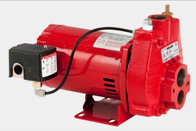
Watch out: convertible jet pumps like the Red Lion RJC-100 (shown at above left) that can be swapped between a shallow well (typically from 25 ft) one-line jet pump to a deep-well two-line jet pump are typically capable of lifting (in the 2-line jet pump conversion) from a depth of about 90 feet.
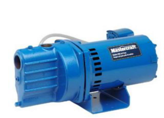
A few one line jet pump models (such as the Mastercraft one line jet pump shown at above right) advertise that they can lift from 70 feet, but if you take a closer look at the pump specifications you may find that although the pump can lift water from that depth its flow rate capacity in gallons per minute (GPM) may be significantly reduced.
For deeper wells using a 2-line jet pump you may require a different pump model.
Contact the Red Lion pump company in the U.S. or Canada at:
RedLion Pumps, USA,
301 N MacArthur Blvd.
Oklahoma City, OK 73127-6616 USA
Red Lion Pumps Canada, Sales and Marketing: Suite 101 - 310 De Baets St. Winnipeg, MB R2J 0H4 Canada
You can use ABS piping and plastic elbows that may tolerate vibration with less leak risk; note that the manufacturer emphasizes that the pump should be securely mounted to a solid base.
Reader Comments, Questions & Answers About The Article Above
Below you will find questions and answers previously posted on this page at its page bottom reader comment box.
Reader Q&A - also see RECOMMENDED ARTICLES & FAQs
On 2023-10-21 by InspectApedia DF (mod) - you are pumping water out of the well faster than water flows into it
@Alan,
Usually that symptom means that you are pumping water out of the well faster than water flows into it - the pump rate exceeds the well's flow rate. The well yield is inadequate.
Or put in more human terms: your well is running out of water.
Watch out: if the pump stops delivering water at all, shut it off and give the well time to recover. Else, especially if it's an aboveground jet pump, you risk burning up the pump motor or damaging its impeller
I would start with the suggestions at
WELL YIELD IMPROVEMENT
On 2023-10-21 by Alan
Pumps 20 gallons than loses pressure takes time to pump up
On 2023-08-18 by InspectApedia Publisher - Can I convert to the one line from a two line?
@Lisa,
I think you've been misled. There are dozens of manufacturers and thousands of vendors of two-line jet pumps.
SOME but not all jet pumps can be converted between one-line and two-line systems, depending on the pump brand and model.
But if your well was already relying on a 2-line jet pump that probably means that the pump is already drawing water from a depth greater than 27 feet (the maximum that a 1-line jet pump can lift water). In that case you can not simply change your 2-line jet pump to a 1-line jet pump because the 1-line version won't have enough lift.
Check with your local plumbing supplier, hardware stores, building supply stores and on-line vendors: you'll have no trouble finding a replacement 2-line jet pump if that's needed.
On 2023-08-18 by Lisa
I have an old 2 line jet pump noone sells them only one line jet pumps...Can I convert to the one line?
On 2023-08-03 by InspectApedia Publisher - Can I put a check valve on 1 1/4” line on 2 pipe well pump between pump and leaking foot valve
@Ira,
Yes some plumbers recommend trying that "fix" first before making the real repair of pulling the piping and replacing the foot valve.
On 2023-08-02 by Ira
Can I put a check valve on 1 1/4” line on 2 pipe well pump between pump and leaking foot valve
On 2023-08-03 by InspectApedia Publisher - don't mix up flow rate (gallons per minute) with "pressure"
@Paul Hamilton,
Let's don't mix flow rate - gallons per minute with "pressure".
You can measure pressure with no water being run - that's the 60 psi at the gauge that you report (I am guessing).
Yes you can adjust the water pressure regulator to send more water in gpm to the building.
I don't usually see a separate water pressure regulator on a 2 line jet pump system but if that's what you've got, see
WATER PRESSURE REGULATOR ADJUSTMENT
On 2023-08-01 by Paul Hamilton
I have 60 psi at the gauge but very little volume at the outlet after the pressure regulator. I can increase the pressure by adjusting the regulator with no change in volume. HELP?
On 2023-02-18 by InspectApedia Editor
@Ronald Reedy,
At that depth, you'll need a two-line jet pump but I need you to clarify the sizes you mention.
The diameter of a residential water well casing is typically 4", 5", or 6".
Injectors are used on two-pipe deep well systems in well casings that are 4" in diameter or larger. An injector won't fit into a smaller diameter well.
So I'm not clear on what you've got and what you're trying to do.
On 2023-02-18 by Ronald Reedy
I have a 2" Galv well casing
I am trying to get an idea of the pump I need. I want to put a galvanized 1 inch single drop line with the injector on the drop line the well is drilled to 120 feet and the water head is at 30 foot what pump would do the job.
On 2022-10-05 by InspectApedia-911 (mod)
@Gandolfi Attilio,
The smaller diameter line is the one that sends water down to the Venturi to pick up more water and bring it back so you start by priming the smaller diameter line and the pump body itself.
On 2022-10-05 by Gandolfi Attilio
Hi…I have a two lines jet pomp..to prime the pomp the two line must have water inside..if only one which one….thank u for your time for a answer ,have a nice day…!
On 2022-03-22 by Inspectapedia Com Moderator
@Jordan,
Yes. You may need more than one check valve on a deep well with a two-line jet pump.
On 2022-03-22 by Jordan
I have a 170-ft deep well. Can it draw water with a twin pipe system if the water table is 60 ft below ground?
On 2015-05-15 by DanJoeFriedman (mod) - can you use a two line jet pump for a shallow well by using only one line going into the well?
Yes Michelle but you'll have to convert the 2-line pump to a 1-line pump and you'll need to know that you're pumping up from 25 ft. or less.
On 2015-05-15 by Michelle
can you use a two line jet pump for a shallow well by using only one line going into the well?
On 2022-09-06 by InspectApedia-911 (mod) - place the injector within 25 feet of the stream?
@Dennis,
I certainly think the 25 ft option is worth trying
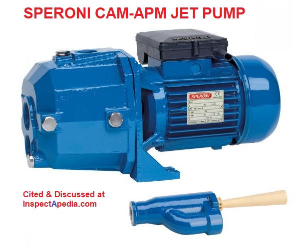
For other readers, here is the APM Jet Pump INSTRUCTION MANUAL [PDF] Speroni, Italy, for this electric self-priming jet pump.
On 2022-09-05 by Dennis
Thanks for your response. I have visited the links you recommended. Unfortunately, the Speroni user manual is rather skimpy on details, but the website [dis-allowed link] suggests a "total suction lift up to 35 mt," which doesn't exactly tell me how long the tailpiece may be. In any case, would it work to place the injector within 25 feet of the stream and increase the length of the two lines running between the pump and injector?
Additionally, the injector is "designed" for a 1'' suction line, but based on the information from VersaJet site, it make sense to increase the diameter to 1.5" or 2". If I increase the length of the two lines running from the pump and injector, so I also need to increase their diameter?
Thanks again,
Dennis
On 2022-09-05 by InspectApedia-911 (mod) - is it necessary to place the injector WITHIN the steam with two lines running from the house?
@DENNIS,
Thanks that's an interesting project and a helpful question.
The injector itself does not have to be at the very end of the pair of water pipes in a 2-line jet pump system.
Sometimes a tailpiece, extending down another 30 feet or more feet is used to avoid running the injector "dry" in a low-yield well.
But Watch out: I suspect that the 50 foot "lift" you describe might exceed the permissible tailpiece length for your pump.
Check with your pump's IO manual for the maximum tailpiece length. Typically pump manuals limit the tailpiece to 25 ft. while others a bit longer (Franklin goes to 34 ft).
Here's an excerpt from these FRANKLIN CONVERTIBLE VERSAJET PUMP INSTRUCTIONS [PDF]
TWIN PIPE INJECTOR INSTALLATION
Prepare the twin pipe deep well injector for installation into the well as outlined in the instructions (document 106581102) provided with the injector kit (ordered separately).
The foot valve strainer can be installed onto the bottom of a 34’ tail pipe, rather than the bottom of the injector, to prevent over pumping of a low yield well.
Lower the injector assembly into the well. It should be set at least 3’ below the lowest dynamic water level if you are not using a tail pipe below the injector.
The foot valve
strainer should be no closer than 3’ from the bottom of
the well.
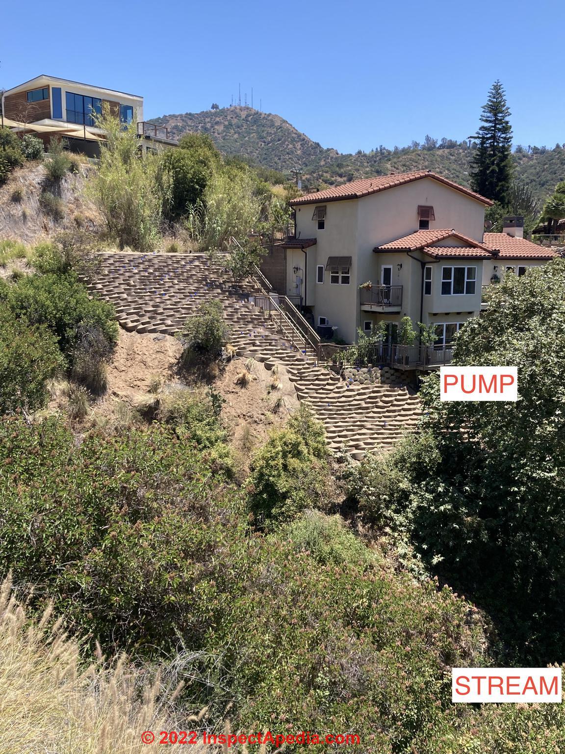
Watch out: as your lift is not straight vertical - from the photo we see there's some horizontal travel - you may need to increase the diameter of the suction line - also discussed in the document we cited above.
I'm looking further to see what the lift limitations are for the tailpiece length or drop pipe length in a 2-line jet pump installation -
details are at WELL PIPING TAIL PIECE
On 2022-09-05 by DENNIS - where to place the well piping injector?
I recently purchased a deep well pump to pump water from a shallow stream to my house to irrigate the yard using a garden hose. The stream is about 3 feet deep. The pump: 1.5 HP Deep Suction Well Jet Self Priming Pump – 552 GPH – APM 150(P30). The stream is about 3 feet deep.
I plan to place the pump next to the house, which is about 50 feet above the street with a run of about 75 feet from the stream.
Regarding the injector, it is necessary to place the injector WITHIN the steam with two lines running from the house down to the injector, or may be injector be placed closer to the house (see image) with only one line running down to the stream (see image).
Secondly, if the injector is close to the house, may the foot valve be placed adjacent to the injector or is it better to place it at the end of the line in/near the stream?
Thanks so much for your help.
Dennis
On 2022-07-22 by InspectApedia-911 (mod)
@don,
Details? What's coming apart, a connection?
Is there water hammer?
What pressure is on the gauge just before the blowout?
How high is water in the casing?
Is the foot valve jammed in clogged?
On 2022-07-22 by don
i have a 2 pipe myers ejecto water pump and the 11/4 pipe blows out of the casing
On 2022-06-02
by InspectApedia (mod) - short cycling in that you described is caused by a waterlogged pressure tank
@Stephen,
The short cycling in that you described is usually not a pump problem.
Instead, that's usually caused by a waterlogged pressure tank.
In any case, if you've already bought a new pump and are going to install it, you can try leaving the existing foot valve in place in the well.
On 2022-06-02 by Stephen
I need to replace my old two line Goulds .5 HP jet pump with a new one, also a Goulds .5 HP, though not the same model. My question is do I need to pull up the pipes and put in a new jet assembly at the same time? (Note: The old pump was experiencing short cycling problems, and would turn on even after filling several glasses of water.) Thanks.
On 2022-01-15 by Inspectapedia Com Moderator - two line jet pump keeps losing pressure
@Jeff,
If your system loses pressure after the pump stops and when you are dead certain no water is running in the house then yes I'd be looking for a leaky foot or check valve or a leak in well piping.
On 2022-01-15 by Jeff
I have a two line jet pump. It keeps loosing pressure, when I turn the valve that shuts the tank off from the pump the pump short cycles very quickly. I think it's something to do with the foot valve or a crack in one of the lines. Is this a good guess? Thanks.
On 2021-07-19 by inspectapedia.com.moderator - a two line jet pump can pump from shallow depths
@Brian R. in NH,
A two line jet pump can pump from shallow depths, though it's an unnecessary approach - a bit of over-kill;
But you need BOTH lines used properly or your pump won't work;
The small diameter pipe sends water from the pump down to a foot valve and venturi at the bottom of the well or pond water source; there water squirts through a venturi to send a larger volume of water back up the larger diameter pipe to the 2-line jet pump and thence to the water's final destination - irrigation in your case.
Be sure to read the article above on this page and also your pump IO manual so that you have a clear picture of how a 2-line jet pump works.
On 2021-07-19 by Brian R. in NH
I just replaced a single line Gould Jet Pump with a Two Line Pump (also a Gould, 1/2 HP) to pump water from my shallow pond for irrigation. Is there any reason a two-line pump won't work for this application? How should I use the "return" line? Is it possible that I could use it to help aerate the pond or drive a fountain?
On 2021-07-09 by inspectapedia.com.moderator (mod)
@James,
Check the model of your pressure control switch. And your other controls. Is there a pump protection circuit.?
On 2021-07-09 by James
pressure tube is clear
On 2021-07-07 - by (mod) -
@James,that doesn't sound like a water table problem, James, unless your pump is also being turned off by a separate pump protection switch feature (that activates when the pump isn't finding water)
Check for a blocked tube or pipe conducting water pressure to the switch first.
On 2021-07-07 by James
I have a two-line jet pump. I can activate it manually by holding the switch down, and it will pump water and hold pressure. When I release pressure, for example by opening a hose valve, the pump does not turn on. I have replaced the switch. Could this be the result of a lowered water table (we're in a severe drought)?
On 2021-06-22 by inspectapedia.com.moderator (mod) - how far below the surface of the water should the inlet hose be?
@pumped,
Because you describe a venturi I am guessing you're talking about a 2-line jet pump system. A 2-line jet pump uses a venturi valve at the bottom of its pair of water pipes (water down one and more water up the other) to bring up water from the bottom of a well or from a pickup point in a lake or water tank.
A river water pump could also work with a 1-line jet pump as long as the TOTAL vertical lift from pick-up point in the river to end use point is less than 27 ft.
A 2-line jet pump, in comparison, can lift water hundreds of feet.
It is the flow of water through the valve, not the depth of the valve, that allows the system to work.
Putting the pick up point for your river water pump deeper into the water makes no meaningful difference in the pump's ability to deliver water. (At about 30 ft. of depth under water we reach 1 ATM of pressure or about another 14.6 psi. )
But the depth of a river water pick-up for a 2-line or 1-line jet pump can be important for other reasons:
1. the water pick-up point for any water pump system needs to be high enough off the bottom to avoid picking up sand or silt and mud - those will foul the whole water system.
In a well that may be 4-10 ft. In a river or lake a similar depth is probably safe though on lake pump systems I've examined in New York, Minnesota, and other US states often permit the pump to sit on the very bottom when the bottom is fully covered by large rocks.
2. in a freezing climate the pick-up point for water needs to be deep enough below the water surface that it won't become encased in solid ice.
3. In a lake or river water pumping pick-up system it's generally better for the pick up point to be more-distant from the shoreline.
Particularly in large lakes where distancing from the shore is actually achievable, getting more than 10 meters from the lakeshore reduces the level of shore-sourced bacteria and other pathogens that will be delivered by the water system.
On 2021-06-22 by pumped
how far below the surface of the water should the inlet hose be?
Deeper is better or worse?
i.e. does the venturi rely on WATER PRESSURE, i.e the WEIGHT OF WATER IN THE RIVER?
On 2021-04-05 - by (mod) -
@ralph ferrier, I'll be glad to help but need to be sure I know what we're discussing. The "jet pumps" discussed on this page are operated by an electric motor.I'm confused by your reference to a "jet hand pump"
Take a look at WATER PUMP LIFE EXPECTANCY at https://inspectapedia.com/water/Well_Pump_Life.php
where we include photos and notes to identify different types of water pumps.
On 2021-04-04 by ralph ferrier
my daughter has two jet hand pumps outside, one leaks water. how do i fix this
On 2021-04-01 - by (mod) -
@Robert,Sure: I would call Jacuzzi directly at 1-844-602-6064
or you can go to the company's contact page at https://www.jacuzzi.com/en-us/contactus.html
On 2021-04-01 by Robert
I have a Jacuzzi 15DDD1-S 1 1/2 hp pump and trying to find a rebuilt kit #05388905K . Does anyone know where I can order one?
On 2021-03-25 - by (mod) -
@Jim, there are a number of possible explanations for the problem you describe including leaks in the well piping. Another common possibility is that the injector or Venturi at the bottom of your two pipe system in the world is clogged or damaged.On 2021-03-25 by Jim
I have a two pipe well system in a 2" casing. The suction pipe goes to the bottom and has a foot valve. The pressure line just pushes water through the cap and fills the gap between the suction pipe and the well casing. My well stopped supplying water.
I've used my neighbor's hose to prime the pump but in the end, the pressure pipe builds pressure but the suction line produces no water. We lost all water in the house.
I had a spare pump so I swapped the old one out so I assume that part of the system is working. It seems to me that I must have some sort of issue with the suction. side of the system.
The pump is connected to the well head with plastic pipes on barbed fittings. There seems to be water leakage from both the lines between the well head to the pump. Could this be the problem? Or is there something else I should check?
On 2021-03-17 by (mod)
@Anonymous, I think so, in that if we fill only the down-pipe, when it pushes water up from the foot valve in the well (and the injector therein) all of that air that was in the riser-pipe (the larger diameter pipe) will be pushed into the pump; the result could be that the pump impeller becomes air-bound.
On 2021-03-17 by Anonymous
Do both pipes need to be full to the pump head to work properly
On 2020-10-08 by (mod) - replace injector in old 2 line jet pump
Larry:
If you are trying to replace the front end of an old well pump that's no longer sold, you'll probably have to buy a new jet pump. That's because pump front-ends or injector assemblies are not universal.
But before throwing-in the towel on your old pump, take it to your local plumbing supplier to see what they have at hand.
On 2020-10-08 by Larry Lutes
I have a 3 1/2" drilled well and need an injector for deep well 2 line system.My existing one has rotted and i need to locate a new injector.My pipe sizes are 1 1/4" suction and 1" drive line.Is anyone still making them?Thank you.
On 2020-10-04 by Moderator Daniel Friedman
Raguram
If no settings such as the pressure control switch were changed then the problem may be loss of water at the source, such as a well, used to fill your tank, or the pump itself may be failing - a clogged or dirty impeller.
Search InspectApedia or check the ARTICLE INDEX above to find our diagnostic and repair article on WATER QUANTITY IMPROVEMENT
On 2020-10-04 by Raguram
We are using jet pump for water delivery in over head tank.now a days it delivers very low quantity.how to increase water delivery quantity..
On 2020-07-19 - by (mod) -
Becky
If the toilet was running continuously that may have run out water from your well.
Try this:
1. turn off power to the pump immediately
2. Leave the pump off for an hour or more - giving the well a chance to "recover"
3. turn off water supplied to the toilet or at least double check that no toilet is running and there is no leak or other continuously-running water in the home.
On 2020-07-19 by Becky
For outage and my sister use the toilet and now I can't get water from my well
On 2020-06-30 - by (mod) -
Corey
Check the manufacturer's instructions. Some jet pumps, but not all, can indeed be converted between 1 line and 2 line versions by separating the front end or impeller assembly.
On 2020-06-30 by Corey Dubel
Ok so my house set up is for 1 line the jet pump that i got is for 2 line jet pump can i cap it off or exchange the front
On 2020-06-25 - by (mod) - Could a two line jet pump be used as a single line by merely plugging the pressure line?
No, in that Arrangement - just plugging one of the lines means that your 2 line jet pump won't pump any water.
It may help to understand how a 2 line jet pump actually works; the "pumping" occurs when the pump sends water DOWN to the venturi that's at the bottom of its pair of well pipes.
There water squirts through the venturi, causing a larger volume of water to return back up the larger of the two 2-line jet pump pipes and onwards into the building water system.
Blocking either of those lines means no water.
But some jet pumps are convertible to single line from two line by changing the front end of the pump to a one-line jet pump system.
On 2020-06-21 by Anonymous
Could a two line jet pump be used as a single line by merely plugging the pressure line?
On 2020-05-14 - by (mod) - Can the ejector go closer to pump?
 Dennis:
The ejector in a 2 line jet pump needs to quite close to or even below the surface of the water, in the well, though you'll see in our ejector tailpiece illustrations that it does not have to be at the very bottom of the well piping.
Otherwise it can't generate the required lift.
To be clear about how your 2 line jet pump is working to deliver water to the building
in the building or somewhere above ground a 2 line jet pump includes an impeller that pushes water down the smaller-diameter well pipe and near the bottom of that pipe, in the well, water is pushed through a jet or venturi - an opening shaped like a funnel.
The venturi, by reducing the opening size in a funnel shape, increases the speed of water passing through the venturi - also called the "injector".
That increase in water creates a suction that draws additional water up through the tailpiece, into the injector, and the combined volume of water sent down the pipe plus additional water sent up the larger pipe back to the pump is what actually delivers water into the building.
The maximum length of the tailpiece is 25 feet.
Why 25 ft. for the maximum tailpiece length?
It's no coincidence. The lift force generated by a venturi is capable of drawing water up in any application is about 25 ft.
So the deep well 2 line jetpump tailpiece length limitation of 25 ft. derives from the same limitation that tells us that a shallow well 1 line jet pump can not lift water from a depth of more than 25 ft.
The difference is that a 1 line jet pump's venturi is above ground, while the 2 line jet pump's venturi or injector is down in the well.
The additional "lift" capacity of the 2 line jet pump comes from the added force or "push" generated by that smaller-diameter pipe that is pushing water down the well piping as well as pushing it back up the well piping to the surface.
On 2020-05-14 by Dennis
Can the ejector go closer to pump
On 2020-05-08 - by (mod) - will our water pump be adequate?
Colin
You'll want to know the water pump brand and model. Then we can check the manufacturer's capacity tables. It's not just "can the pump pull the water" it's also - at what flow rater or gpm will it deliver water to plumbing fixtures in the home. Higher lift and more resistance in long piping means lower flow rates.
See details at WATER PUMP CAPACITIES TYPES RATES GPM https://inspectapedia.com/water/Well_Pump_Capacity.php
On 2020-05-08 by Colin1956
We are installing a new water line at our place running from the lake to the back of the house. We will have a lift of approx 12' but a run of 250' from the foot valve in the lake to the pumphouse, Foot valve to shore is 130' with 130' from the shoreline to the pump house.
We have a 3/4 HP convertible well pump. Will the pump be able to pull water that distance? If so, would we go with the two hoses or one? Thanks.
On 2020-04-23 - by (mod) -
Paul:
Perhaps you can post some photos of your pumps, old, new, and the piping feeding and leaving your original jet pump.
It'd help to know the brand and model of both pumps.
As we see in photos on this page, a typical 2-line jet pump has three points of pipe connection;
1. water going down to the venturi/foot valve
2. water coming up from the well
3. water supplied to the building
I suspect that your new jet pump is a "convertible" model that can be hooked up as either a 1-line jet pump or a 2-line jet pump, and that it came out of the box set up as a 1 line jet pump. You may need to purchase a front-end converter to set the pump up as a 2-line system.
Above on this page you'll see photos of jet pumps in both configurations.
On 2020-04-23 - by (mod) - deep well jet with Double-Drop Jet-Pump System
Brian,
If you tee off of the return line of a 2-line jet pump system, when the pump is running some of that return water will head directly to your sprinkler system. That might work if there is no check valve between the tee-off and the inlet to the pressure tank and/or section of piping sending pressure to the pressure control switch.
On 2020-04-23 by Brian
I have a deep well jet with Double-Drop Jet-Pump System. I'd like to use a separate sprinkler pump to irrigate my garden. Can I Tee off the suction line coming out of the well into my sprinkler pump?
On 2020-04-23 7 by Paul
I have a two line well system my pump went out and I got a new one the old pump had three inlets and the new one has two inlets?
On 2020-04-10 - by (mod) - Can I use a 2-line jet ejector system on an existing 3 inch diameter PVC well casing?
Yes, Jonathan but you'll be reducing the flow capacity of the system.
You might want to try selecting the actual ejector venturi size to get the best flow from your well without exceeding the well's recovery or flow rate capacity.
Betta Flo and also Sta-Rite are examples of sources of jet / venturi / tailpiece components.
On 2020-04-10 by Jonathan
Hi,
Can I use a 2-line jet ejector system on an existing 3 inch diameter PVC well casing?
Thanks and regards
Question: It is necessary to extend the injector to the bottom of the water?
2020/04/09 Francis Carlo said:
It is necessary to extend the injector to the button of the water?
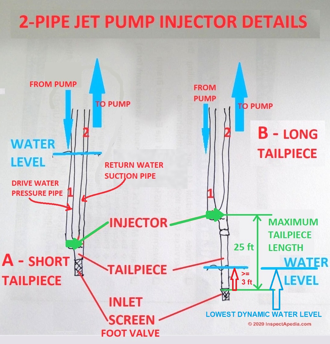
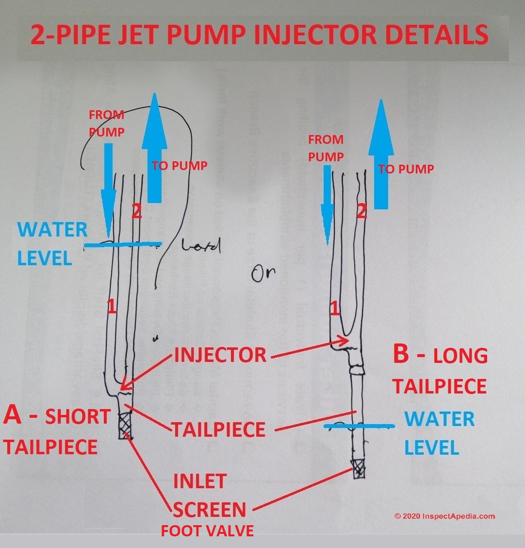
Reply: the injector can be above water level with a sufficiently long tailpiece but ... watch out!
Francis
Injectors are used on two-pipe deep well systems in well casings that are 4" in diameter or larger. (An injector won't fit into a smaller diameter well but you may be able to use a packer-well assembly in those smaller casings.)
Both of the 2-line jet pump injectors in your drawing (shown here with my edits) can work as long as the length of the tailpiece does not require a greater water lift suction than the injector can provide.
We know that a 2-line jet pump works by sending water down smaller-diameter pipe #1, through the injector, and with help from additional well-water picked up by the injector, a larger volume of water returns to the pump through larger diameter pipe #2.
The injector's lift capability is determined by the venturi design, size, and the flow rate of water moving down through pipe A.
Watch out: unless your well has a very high water flow-rate, a short tailpiece and injector above the water level is going to give only a very limited volume of well water before the well water level drops below the well screen or foot valve - you will run out of water quickly.
Note that at least some of the pump manufacturer's installation recommendations we've reviewed recommend that the injector be located 10-20 feet below the lowest point to which water is expected to be drawn down in the well casing.
Thank you for asking - working together helps us both.
Question: two line Jacuzzi jet pump will run and stop constantly.
 (Mar 14, 2020) Josh Faulkner said:
Hello. I have scoured the internet and cannot find anything relevant to what I am experiencing. Recently, our well system has been acting strange. Our two line Jacuzzi jet pump will run and stop constantly.
However, when it stops, it immediately loses pressure (it's a 30-50 pressure switch setting) and a pretty large amount of water will rush in from the casing that the two lines run through to exit the foundation.
I am so worried about what this means! Please someone give me some ideas. Thank you.
Reply:
Josh
1. separate the water systems in your home so that we know which components are involved with this issue and which are not.
confirm that you do or don't have
- house water supply: a 2-line jet pump and a deep well supplying water to the home
- a Jacuzzi jet pump that circulates water in the Jacuzzi?
and water supply into the Jacuzzi system from the house water system
so
Turn off all water into the Jacuzzi and turn off all of its equipment.
Then
Does the house water supply work normally or is the house water system cycling on and off?
See WATER PUMP SHORT CYCLING - home - for diagnostic and repair procedures.
Question: how to prime a pump with no primer access opening
(Feb 19, 2020) Anonymous said:
Ive pulled the 2 lines to replace foot valve, should I fill the lines with water after returning them in casing to help yhe priming process /
there is no primer access on pump itself so do I just remove the pressure gauge and prime it through that pipe ?
Reply:
Anon:
It's unusual to have no possible primer opening right on the jet pump - please tell me the brand and model and attach a photo of the pump.
But yes if there is a pressure gauge atop the pump impeller housing then you can (very tediously) prime through that opening.
See WELL PUMP PRIMING PROCEDURE for details -
Or you might need to add a tee fitting on the well piping to use for priming.
Watch out: Take care not to run the pump "dry" or it could be damaged.
Question:
Norm said:
I have installed a shallow 2-pipe system and can't maintain prime. I have tested all of the piping, including suction, at 30 psi and there are no apparent leaks.
I installed a check valve about one foot above water (a brook) and have a submerged slotted well screen assembly (nine feet of horizontal 2" slotted PVC well pipe with 10 mil slots).
The ejector is about 100 feet away from the brook, but only about four feet vertically above the water. In theory it should work but unless I continually add water at the pump (in the cellar, about 500 feet away from the ejector) it loses prime.
Any ideas?
Reply:
Look for an air leak - it could be in a pipe, pipe connection, pump itself, or bad foot valve.
Isolate the building by turning off water into the building to assure it's not on the building side.
...
Continue reading at WATER PUMP, TWO LINE JET PUMP OPERATION or select a topic from the closely-related articles below, or see the complete ARTICLE INDEX.
Or see TWO LINE JET PUMP FAQs - questions & answers posted originally at this article.
Or see these
Recommended Articles
- AIR DISCHARGE at FAUCETS, FIXTURES
- NO WATER PRESSURE - no water at all
- SHORT CYCLING WATER PUMP - pump keeps turning on and off rapidly
- VARIABLE FREQUENCY / VARIABLE SPEED DRIVE WELL PUMPS (VFDs)
- WATER PRESSURE INTERMITTENT LOSS - occasional loss of water pressure
- WATER PRESSURE LOSS DIAGNOSIS & REPAIR - home
- WATER PUMP CONTROLS & SWITCHES - home
- WATER PUMP DIAGNOSTIC TABLE
- WATER PUMP INTERMITTENT CYCLING - pump cycles on and off at odd times or for no apparent reason
- WATER PUMP, ONE LINE JET
- WATER PUMP PRESSURE SWITCH MANUALS
- WATER PUMP PRIMING PROCEDURE - prime the pump using a garden hose or by other means
- WATER PUMP PROTECTION SWITCH
- WATER PUMP REPAIR GUIDE - home
- WATER PUMP, SUBMERSIBLE
- WATER PUMP, TWO LINE JET
- WATER PUMP, TWO LINE JET PUMP OPERATION - read this next
- WATER PUMP WONT STOP RUNNING - pump runs continuously, never shuts off or can't reach shut-off pressure
- WATER PUMP & TANK I&O & REPAIR MANUALS - manuals for water pump controls, pumps, tanks
- WATER TANK: USES, TROUBLESHOOTING
- WELL PIPING CHECK VALVES
- WELL PUMP PRIMING PROCEDURE if you need to re-prime your jet pump.
- WELL CAPS & COVERS - requirements for sealed well caps & covers, requirements for vents & exclusion of vent requirements for some jet pump installations.
- WELL PIPING TAIL PIECE
- WELL WATER PRESSURE DIAGNOSIS
Suggested citation for this web page
WATER PUMP, TWO LINE JET at InspectApedia.com - online encyclopedia of building & environmental inspection, testing, diagnosis, repair, & problem prevention advice.
Or see this
INDEX to RELATED ARTICLES: ARTICLE INDEX to WATER SUPPLY, PUMPS TANKS WELLS
Or use the SEARCH BOX found below to Ask a Question or Search InspectApedia
Ask a Question or Search InspectApedia
Try the search box just below, or if you prefer, post a question or comment in the Comments box below and we will respond promptly.
Search the InspectApedia website
Note: appearance of your Comment below may be delayed: if your comment contains an image, photograph, web link, or text that looks to the software as if it might be a web link, your posting will appear after it has been approved by a moderator. Apologies for the delay.
Only one image can be added per comment but you can post as many comments, and therefore images, as you like.
You will not receive a notification when a response to your question has been posted.
Please bookmark this page to make it easy for you to check back for our response.
Our Comment Box is provided by Countable Web Productions countable.ca
Citations & References
In addition to any citations in the article above, a full list is available on request.
- Access Water Energy, PO Box 2061, Moorabbin, VIC 3189, Australia, Tel: 1300 797 758, email: sales@accesswater.com.au Website: http://www.accesswater.com.au/
Moorabbin Office: Kingston Trade Centre, 100 Cochranes Rd, Moorabbin, VIC 3189
Australian supplier of: Greywater systems, Solar power to grid packages, Edwards solar systems, Vulcan compact solar systems, water & solar system pumps & controls, and a wide rage of above ground & under ground water storage tanks: concrete, steel, plastic, modular, and bladder storage tanks. - Alberta, DEEP WELL JET PUMPS [PDF], Government of Alberta, Agriculture and Rural Development, toll free in Alberta at 310-FARM web search 07/24/2010, original source: http://www1.agric.gov.ab.ca/$department/deptdocs.nsf/all/agdex639
- Betta-Flo JET PUMP INSTALLATION MANUAL [PDF], National Pump Co., LLC., includes helpful well pump troubleshooting tips as well as basic jet pump installation details. Web search 07/24/2010, original source: http://www.nationalpumpcompany.com/Documents/OIM/Betta%20Flo%20IOM%20Jet%20Pump.pdf
- Lancaster, JET PUMP INSTALLATION MANUAL [PDF] Lancaster Pump (Division of C-B Tool Co.), 1340 Manheim Pike, Lancaster PA 17601-3196 USA, Tel: 717-397-3521, Website: www.lancasterpump.com Email: info@lancasterpump.com retrieved 2020/04/14, original source: http://lancasterwatergroup.com/wp-content/uploads/Product_Manuals/SKC-2SW-2DW-jetpumps.pdf
- National Pump JET PUMP INSTALLATION MANUAL [PDF] Gorman Rupp Co., National Pump Div., National Pump Company, 7706 N. 71st Avenue, Glendale, AZ 85303-1703 USA, Tel: (623) 979-3560
(800) 966-5240 Email: info@natlpump.com Website: https://www.nationalpumpcompany.com
Retrieved 2020/05/14, original source: https://www.nationalpumpcompany.com/wp-content/uploads/2016/12/JETPUMP_IOM_7-2016_FINAL.pdf
Includes notes on installing both 1-line and 2-line jet pumps as well as a water pump troubleshooting guide - Penn State, Water Fact Sheet #3, USING LOW-YIELD WELLS [PDF], Penn State College of Agricultural Sciences, Cooperative Extension, School of Forest Resources, web search 07/24/2010, original source: http://pubs.cas.psu.edu/FreePubs/pdfs/XH0002.pdf
- Flexcon, SMART TANK INSTALLATION INSTRUCTIONS [PDF], Flexcon Industries, 300 Pond St., Randolph MA 02368, www.flexconind.com, Tel: 800-527-0030 - web search 07/24/2010, original source: http://www.flexconind.com/pdf/st_install.pdf
- Grove Electric, Typical Shallow Well One Line Jet Pump Installation [PDF], Grove Electric, G&G Electric & Plumbing, 1900 NE 78th St., Suite 101, Vancouver WA 98665 www.grovelectric.com - web search -7/15/2010 original source: http://www.groverelectric.com/howto/38_Typical%20Jet%20Pump%20Installation.pdf
- Grove Electric, Typical Deep Well Two Line Jet Pump Installation [PDF], Grove Electric, G&G Electric & Plumbing, 1900 NE 78th St., Suite 101, Vancouver WA 98665 www.grovelectric.com - web search -7/15/2010 original source: http://www.groverelectric.com/howto/38_Typical%20Jet%20Pump%20Installation.pdf
- Water Ace Jet Pump Installation Manual, instructions from Water Ace Pump Co., web search 08/28/2010, original source: http://www.waterace.com/pdf/R510%20R520%20and%20R100%20Jet%20Pumps%20Manual.pdf
Consumer hotline: 800-942-3343 - instructions for the installation and maintenance of
Water Ace shallow well pump Model R510 1/2 HP
Water Ace deep well pump Model R100 convertible 1HP and
Water Ace deep well jet pump Model R250 convertible 1/2 hp.
Quoting from the company's website:
The Water Ace Pump Company is a dynamic, rapidly growing retail pump manufacturer, backed by a tradition of over 125 years of excellence. We offer a complete line of sump, sewage, lawn sprinkler, swimming pool, submersible well and jet pumps as well as pressure tanks and accessories. - Water Ace Jet Pump Installation Manual, from Water Ace Pump Co., web search 08/28/2010, original source: http://www.waterace.com/pdf/RTS5%20RTS7%20RTS10%20RC5%20and%20RC10%20Jet%20Pumps%20Manual.pdf
Consumer hotline: 800-942-3343 - instructions for the installation and maintenance of Water Ace pump models:
Water Ace Shallow Well 1-line Jet Pump Models RTS5 (1/2HP), Model RTS7 (3/4 HP) and RTS10 (1HP)
Water Ace Deep Well 2-line Jet Pump Models RC5 (1/2 HP) and RC10 (1HP) - Our recommended books about building & mechanical systems design, inspection, problem diagnosis, and repair, and about indoor environment and IAQ testing, diagnosis, and cleanup are at the InspectAPedia Bookstore. Also see our Book Reviews - InspectAPedia.
- In addition to citations & references found in this article, see the research citations given at the end of the related articles found at our suggested
CONTINUE READING or RECOMMENDED ARTICLES.
- Carson, Dunlop & Associates Ltd., 120 Carlton Street Suite 407, Toronto ON M5A 4K2. Tel: (416) 964-9415 1-800-268-7070 Email: info@carsondunlop.com. Alan Carson is a past president of ASHI, the American Society of Home Inspectors.
Thanks to Alan Carson and Bob Dunlop, for permission for InspectAPedia to use text excerpts from The HOME REFERENCE BOOK - the Encyclopedia of Homes and to use illustrations from The ILLUSTRATED HOME .
Carson Dunlop Associates provides extensive home inspection education and report writing material. In gratitude we provide links to tsome Carson Dunlop Associates products and services.
 | HOME | ABOUT | ASK a QUESTION | CONTACT | CONTENT USE POLICY | DESCRIPTION | POLICIES | PRIVACY | |
| © 2024 - 1985 Publisher InspectApedia.com - Daniel Friedman | |||||||||