
InspectAPedia® FREE Encyclopedia of Building & Environmental Construction, Diagnosis, Maintenance & Repair |
Question? Just ask us! InspectAPedia
|
 Water Pump Controls
A Photo-Guide & Dictionary of Water Pump & Well Controls & Switches
- POST a QUESTION or COMMENT about how to troubleshoot problems with water pump controls, how to repair or replace pump controls such as pressure control switches, check valves, foot valves, and air volume controls
Well Pump & Water Pump Controls:
This article describes and identifies the switches, controls, and safety devices used on water tanks and water pumps such as the pump pressure control switch, pump motor relays, water tank relief valve, water tank pressure gauge, water tank air volume control, and water tank air valve.
We discuss these well or water pump control questions: What are the functions of the well water pump pressure control switch, water tank relief valve, water tank gauge, water pump relays, water tank valves. Well pump & water tank diagnosis & repair procedures.
InspectAPedia tolerates no conflicts of interest. We have no relationship with advertisers, products, or services discussed at this website.
A Dictionary of Water Pump & Water Tank Controls, Switches, & Attachments
 This article uses sketches and photographs to assist in locating and identifying all of the controls and switches found on residential water supply systems including the well, water pressure tank, water pump, and their associated valves and devices.
We also provide maintenance and repair and emergency water shutoff tips throughout these descriptions.
[Click to enlarge any image]
How to Identify Water Well, Pump, & Tank Components & Switches
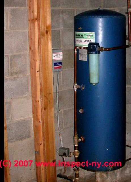
In addition to the individual well, pump, and tank component photographs provided in the article below, our photograph at left has a number easy-to-identify water system components that happen to all be in one place:
- The Well Casing
itself is visible at the right of the photo, in the floor, to the right of the yellow shutoff valve. A well casing is a vertical pipe made of steel or plastic or other material that is inserted into a well bore drilled into the ground to a depth sufficient to find water. - The black plastic well piping
leading from the well casing top to a connection to galvanized piping which then passes by the pressure control switch to a "tee" where water can flow both into the pressure tank bottom (to the right at the tee) and into the building water supply piping (to the left of the tee) - A well casing vent
can be seen as the vertical copper pipe which forms an upside down "U" shape and is connected to a fitting on the cover of the well casing. This well vent permits air into the well during water draw-down during pump operation. Details about well casing cap vents are
at WELL CAPS & COVERS - A water treatment chemical connection,
probably from a chlorine injection system (this well water is probably contaminated with bacteria) can be seen as a clear plastic small diameter tube which is fed through a gray plastic tee in the black plastic well piping that connects the well itself to the galvanized pipe leading to the water tank and house supply piping.
At the upper right in the photo se see two treatment tank bottoms (black and white smaller diameter tank-like objects partly shown). - Well pump wiring
is also visible: twisted wires can be seen entering the well casing cap at the 1-o'clock position on the cap - so we know that this water system uses a submersible (in the well) water pump. - A water softener or other water treatment system
is probably installed besides a chlorine injection system, since we see in the photo's upper right the bottom of two treatment tanks, and because in the upper left of the photo we see a somewhat larger diameter clear plastic tube running right to left and probably serving as a backwash drain tube for a water softener or other water treatment device - Water on the floor
around the water tank and equipment looks like more than we'd find from simple condensation drips - we suspect there's a leak somewhere or a basement water entry problem that needs to be corrected. - NO RELIEF VALVE
is visible in this photo
Watch out: one should have been installed and may be missing. This is a safety defect and in some jurisdictions a plumbing code violation.
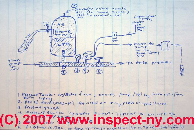
Identification of the Water System Components Shown in the Page Top Sketch
 The page top sketch is expanded by detailed photographs as we explain each of the components and controls of wells, pumps, and water tanks.
In our sketch (sorry the author is a technician but not an artist), you can identify the basic components of a private well system (listed next) but as you'll see in our detailed articles and photos which follow, these components are not always located where they're as easy to spot and name as in our drawing.
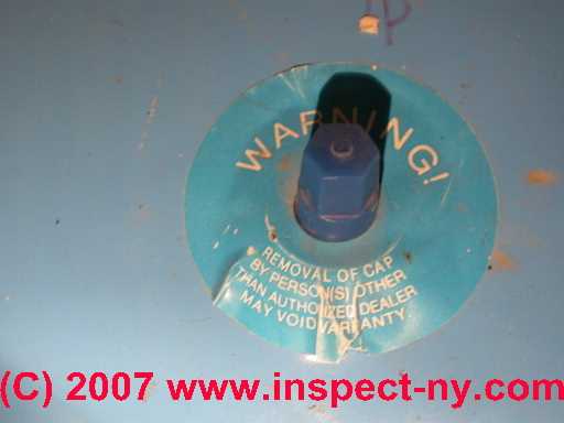
Air valve (Label #7 in the page top sketch and shown in the photo at left) or "Schrader valve" (looks like a tire valve). The water tank air valve shown in this photo is one that you should not normally have to use as it's installed on a captive air or bladder type water tank.
On water tanks that do not use an internal bladder, the air valve, or Schrader valve, used to add air to the water tank can be seen in this photo.
Details are at TANK AIR INLET VALVE.
At WATER TANK AIR, HOW TO ADD we discuss adding the right amount of air to a non-bladder steel or glass-lined well tank.
And at WATER TANK BLADDER PRESSURE ADJUSTMENT we discuss fine tuning the pump pressure control switch to work perfectly with the exact air pressure pre-charge in a bladder type well tank.
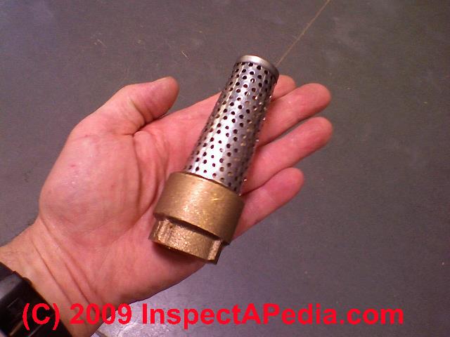
Air volume control (Label #6) and copper or plastic tube connecting the AVC to the water pump or a fitting nearby.
An air volume control valve or device is not presentOn "captive air" bladder type water tanks - this control can take several appearances.
Here is a photo of a different type of water tank air volume control.
Details on using and repairing water tank air volume controls are
at WATER TANK AIR VOLUME CONTROLS
Check Valves on water piping, well pumps, wells. Shown below.
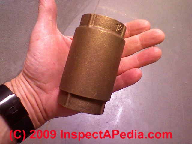
Check valves prevent back-flow of water through piping for any of several reasons such as preventing loss of well pump prime by a check valve located at an above-ground water pump or at the water pressure tank -
see CHECK VALVES, WATER SUPPLY, DRAINS, PUMPS
Electrical Power (Labeled SW in the sketch at page top) - Electrical switch at the water pump.
See WATER PUMP ELECTRICAL SWITCHES
Foot Valves on well piping are located on the bottom of the well piping, inside the water well. The foot valve helps prevent loss of prime in the well pump and piping system when the pump stops running -
see FOOT VALVES
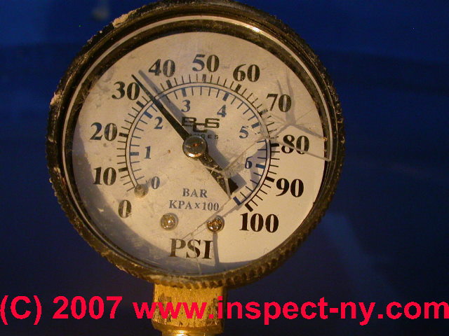
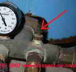
Gauge (Label #3) - Water tank pressure gauge. The water pressure gauge on home water systems is one of the most helpful and simple devices used in diagnosing poor water pressure and pump, well, or pump control problems.
This gauge has broken cover and needs replacement.
See WATER TANK PRESSURE GAUGE for water pressure gauge explanation and repair advice.
We discuss gauge problems with air or water pressure gauge readings on water tanks
at HOW TO READ WATER TANK AIR GAUGE PRESSURE ACCURATELY
Piping (Labeled "from pump & well" at left) - Well piping bringing water from the well to the water pressure tank and building.
See WATER SUPPLY & DRAIN PIPING
Piping (Labeled "to house fixtures" at right )- Building water supply piping a main water line leaving the water pressure tank and bringing water to the building and its fixtures.
Pitless Adapter (shown in sketch below): the pitless adapter provides a water-tight connection that permits the well piping to pass out through the side of a round steel well casing.
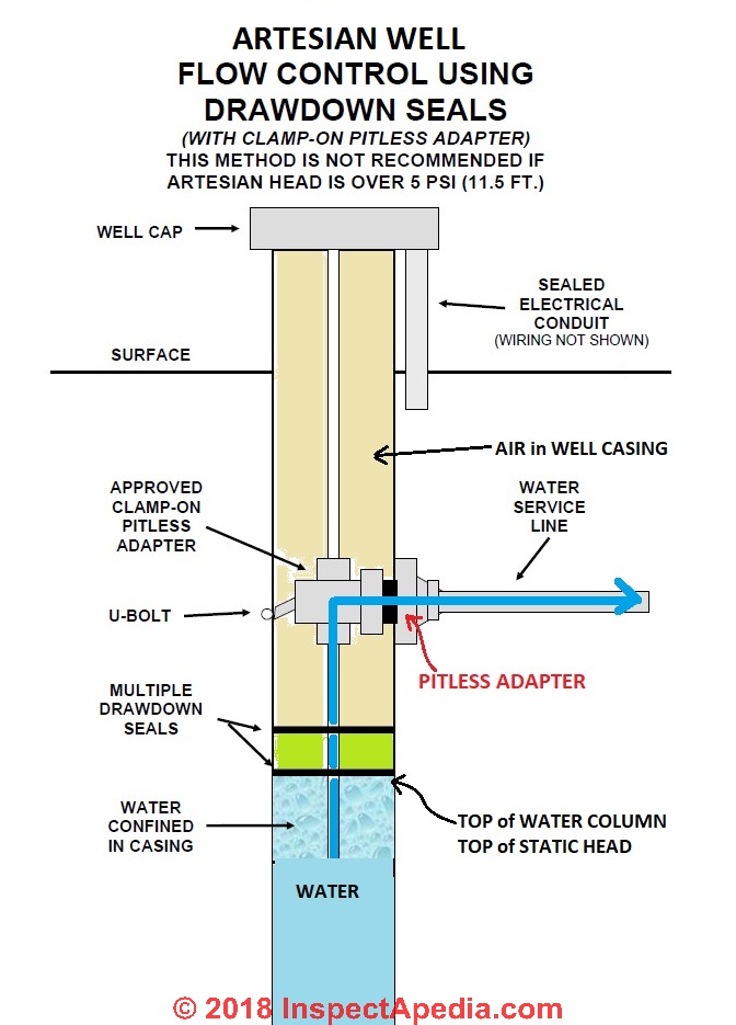
Our illustration (above left) shows a low-pressure well spool using a clamp-on pitless adapter in a design suitable for artesian wells whose head pressure is equal to or less than 5 psi (a head of 11.5 ft.) - courtesy Michigan DEP.
We illustrate and discuss the use of pitless adapters at PITLESS ADAPTER. Also see
- DRILLED WELLS, STEEL CASINGS
- ARTESIAN WELL FREEZE PROTECTION
- ARTESIAN WELLS, WELL SPOOLS
- WELL ABANDONMENT PROCEDURE
- WELL CASING DIAMETER CHOICE
- WELL CASING LEAK REPAIRS
Low Water Cutoff for the Well Pump - Many sources, including the Penn State School of Forest Resources recommend installing a low water cutoff device to protect a well pump that has to operate in an inadequate or low-yield well. That resource describes an electrical low-water cutoff switch.
A low water sensing device to protect a well pump may be installed in an intermediate water storage tank, for example. If your well pump has stopped running and an electric low water cutoff switch is installed you'll want to check that the switch is working properly.
Details about electric and other low water cutoff devices to protect the well pump from damage are described in detail
at WATER PUMP PROTECTION SWITCH
Pump - Water pump either at or close to the water pressure tank or located separately in a well pit (not shown in this sketch) or in the well itself (shown as pump at far center right in sketch at the top of this article ).
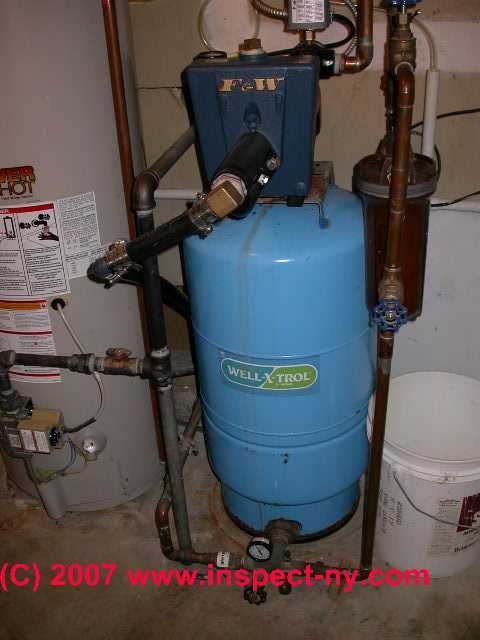
The water pump shown in this photo is installed right on top of the water tank and it is easily identified as a "one line jet pump" since we see only a single pipe entering the pump from the well - the black ABS piping coming into the pump from its lower left.
The outlet of this one line jet water pump is the copper pipe at upper right of the blue pump assembly.
If you do not see a water pump anywhere in the building, and if the property does not use an outdoor well pit or well house, then your well water pump is probably a submersible unit.
Details of the different types of water pumps such as one line jet pumps, two line jet pumps
and submersible water pumps are described in detail at WATER PUMP TYPES & LIFE EXPECTANCY
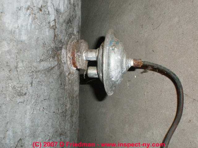
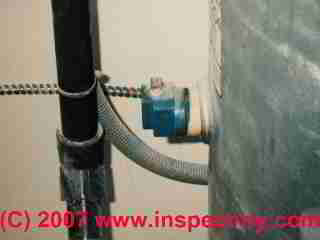
Relay Switch - Pump relay
(Drawn as box at right center in sketch) turns on and off a higher-voltage water pump such as some submersible pumps (not present on all water systems).
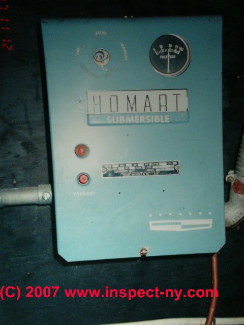
The water pump relay switch is a heavy-duty switch that turns on and off a submersible water pump. Some lower ampacity submersible well water pumps may be switched on and off directly by the pump pressure control switch.)
Shown here is a Homart submersible well pump relay switch.
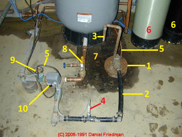
You can see a Gould™ submersible water pump relay switch mounted on the wall in this photograph: WATER TANK (Label #1) [photo]
For details about the water pump relay switch, its use, inspection, and repair,
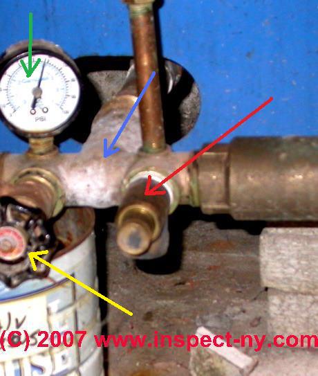
Relief Valve (Label #2)
pressure relief valve on the water tank.
Water tank relief valves (red arrow in photo) were omitted by lots of plumbers installing pump, tank, and well systems, but most plumbing codes and local codes require a pressure relief valve on any tank which contains something under pressure, including a home water tank.
Should the water tank rupture, even at fairly low pressures, a bystander could be hurt or even killed.
This actually happened to a plumber in New York state, making pressure relief valve believers out of plumbers in the area. The tank burst, he was killed.
See WATER TANK PRESSURE RELIEF VALVE
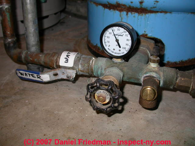
Shutoff (Label #5) - Main water shutoff valve.
A main water shutoff valve, in this case the blue lever labeled "WATER" with white tape is shown to the left of the pressuregauge and pressure tank drain valve in our photograph (white arrow).
Details about water shutoff valves can be found at MAIN WATER SHUTOFF VALVE
Switch, pressure (Label #4) - Water tank and pump pressure control switch.
The well water pump pressure control switch is the "brain" of a home pump and well system, sensing the water pressure in the building and controlling the turn-on (at low pressure or "cut-in" pressure) and turn-off (at high pressure or "pump cut-out" pressure) of the water pump itself.
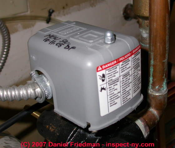 All home water pumps use some type of pressure control switch to turn the water pump on and off.
See WATER PUMP PRESSURE CONTROL SWITCH for details.
The detailed, step by step procedure for inspecting and adjusting the water pressure control switch is
discussed in detail
at WATER PRESSURE CONTROL SWITCH ADJUSTMENTS.
Some well pump pressure control switches incorporate a WATER PUMP PROTECTION SWITCH that may have to be manually re-set.
- How to Adjust Water Pump Pressure:
The detailed, step by step procedure for inspecting and adjusting the water pressure control switch is discussed in detail at
WATER PRESSURE CONTROL SWITCH ADJUSTMENTS. - Diagnosing Water Pump Short Cycling on and off:
If your water pump is clicking on and off too often or quite rapidly
see WATER PUMP SHORT CYCLING - home - Diagnosing Water Pressure Drops
without explanation when the pump stops
, see WATER PRESSURE FALLS SLOWLY, ERRATIC PUMP: bad pressure control switch, building water running or leak, bad pressure gauge, bad check valve, bad foot valve. - Diagnosing & Repairing Lost Air in the Water Tank:
The problem of lost air in the water pressure tank along with how to correct that condition are discussed beginning
at SIGNS OF AIR LOSS.
At WATER TANK AIR, HOW TO ADD we discuss adding the right amount of air to a non-bladder steel or glass-lined well tank.
And at WATER TANK BLADDER PRESSURE ADJUSTMENT we discuss fine tuning the pump pressure control switch to work perfectly with the exact air pressure pre-charge in a bladder type well tank. - Diagnosing & Repairing a Water Pressure Control or Water Pump Control Switch:
We discuss diagnosing and repairing a water pressure control switch that sticks "on" or "off" or simply won't operate,
at WATER PUMP PRESSURE CONTROL REPAIR.
If the water pressure switch is making noises like clicking or humming
see WATER PUMP PRESSURE SWITCH NOISES.
Tailpiece - in the well: The tailpiece is an extension on the bottom of well piping (blue) in our drawing at left.

When the well pump's capacity is known to exceed the flow rate of the well, a tail pipe, tail piece, or low water cutoff control is installed to protect the pump from damage such as that caused by well pump cavitation or motor overheating.
Details about this component and about well pump cavitation are
Tank (Label #1) - water tank: The water pressure tank
showing air in the upper portion and water in the lower portion of the tank. The water pressure tank in most buildings has the job of smoothing the pressure and flow of delivery of water to the building.
At a property whose water well has very limited recovery rate or flow rate, the water tank may be larger, or there may be several of them installed.
In this case the water tank is also storing a buffer quantity of water for use in the home so that the poor well delivery rate does not directly affect the occupants in the building.
Details are at WATER TANK TYPES: WATER, OIL, EXPANSION, ALL.
At WATER TANK AIR, HOW TO ADD we discuss adding the right amount of air to a non-bladder steel or glass-lined well tank.
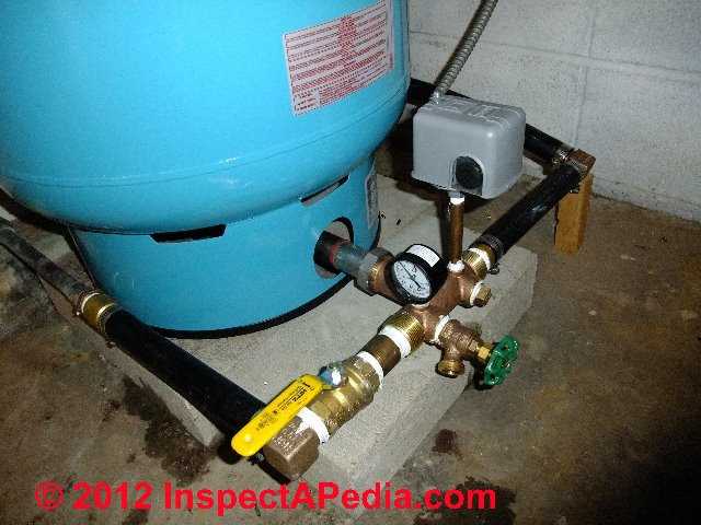
Tee (Label #2) - Bronze tee and water tank pressure relief valve
(not always present, but a relief valve should always be installed - add one if it's missing.)
In our photo abov e you can see the bronze water tank tee (blue arrow) attached to the bottom of a water tank, and providing a plumbing connection point for a water tank gauge (green arrow), pressure relief valve (red arrow), and a tank drain valve (yellow arrow) all mounted in this photograph.
Detailed descriptions of individual water system parts and controls, valves, switches, pumps, piping, etc., how they work, how to diagnose, repair, or replace them are provided in the remaining chapters of this article and are listed just below.
Readers of this document should also
see WATER PUMP REPAIR GUIDE an specific case which offers an example of diagnosis of loss of water pressure, loss of water, and analyzes the actual repair cost.
Reader Comments, Questions & Answers About The Article Above
Below you will find questions and answers previously posted on this page at its page bottom reader comment box.
Reader Q&A - also see RECOMMENDED ARTICLES & FAQs
Dole Valves, Check Valves & safety concerns at a pump and well installation

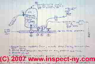
On 2020-06-17 by Andrew - what are the components of my well system?
I am trying to figure out the components of my well system. I have an old air over water expansion tank that a professional driller/well guy told me I should replace.
He also suggested that I get a 7gpm Dole Valve. In the attached image, the guy told me that the line coming up from the ground on the left is from the well and the line to the right goes to the house. Based on all of my searching for designs, this doesn't seem to match.
Every image or video I've seen has the hose bibs on the line going to the house and the line coming from the well seems to always be on the side of the T that the switch is on. Is there a way for me to confirm which line in the image is which?
The well guy suggested that I put my Dole Valve in-line in the poly pipe on the right side of the image. Would that make sense if the line going to the right is the one going into the house?
It also looks like I'm going to need to add a pressure relief valve as my current system doesn't have one. Is this correct?
Thanks in advance for any advice. [See photo above in this discussion - Ed. ]
On 2020-06-17 by danjoefriedman (mod) - where is this valve: on the well side or on the house side of the water pump?
Andrew
Thank you for the photo in the interesting question.
I tend to think the well guy knows what he's talking about. And usually the shutoff is found on the house side of the pressure tank, but that muddy vertical ABS pipe suggests it's the water line up fdrom the well.But I can't see enough of your photo to give an absolutely certain answer. However it should be very easy for us to figure this out.
When you have pressure in the water pressure tank, close the shut off valve that in your photo is to the left of that drain valve. If you are in fact closing off the line between pressure tank and house you will know that right away when you walk back to the house and open a faucet because you may see a brief second or two spirit of water but after that you will have nothing.
Let me know what you find and we'll take it from there
On 2020-06-18 by Andrew
Hey, thanks for that. I thought that may be an easy way to test it. I signed up for this plumbing forum and asked if that would be a legit way to find out and I started to wonder if plumber/well guys just spoke in code to keep the DIYers at bey ;)
If I understand you correctly, I can just turn off that round valve on the left and when water no longer flows to the house or outdoor hydrants, that should indicate that the line on the left is coming from the tank and the line on the right is coming from the well? Is that correct?
On 2020-06-18 - by (mod) - Dole Valves, Check Valves & multiple safety concerns at a pump and well installation
Right.
If the valve is on the "house" side of the tank and pump and well line, then turning that off will mean that no water is delivered to the house.[Click to enlarge any image]
If it's on the "well" side of the system then closing that valve will permit *some* water to enter the house as there is presumably water and pressure in the water pressure tank that will push that water into the house (until its volume and pressure are depleted and of course cannot be replenished from the well as the well isn't in that case connected to the rest of the system)
While a plumber would normally install the shutoff on the "house side" of the pressure tank, people put valves and controls in all sorts of places, sometimes for a reason, or sometimes by mistake. So don't assume. Do the test, let me know what you find.
Watch out: you NEVER want a shutoff valve between the pump and the pressure control switch. If a valve is placed in that location and is closed, turning on the pump can blow up a pipe or pressure tank or whatever is on the pump-side of the valve. Someone can be injured or even killed by the flying debris.Watch out: and yes, I agree that the pressure tank should be protected against rupture by a pressure relief valve. Usually there's a fitting for that on the tank tee but on your tank tee I don't see that feature.
Watch out: if your well is a low-yield well, a Dole Valve, as you suggest, is a means of protecting the pump from running dry. You want to install the valve in the pump discharge line between check valve and pressure tank.
Also see WATER PUMP PROTECTION SWITCH for an explanation of Dole Valves, flow restrictors, & various options to protect the well pump from damage.
(June 18, 2020) Andrew said:
It isn't clear that this is going to appear as a direct reply to the moderator comment above but it is...
Thank you for the information. I appreciate the photo and safety concerns. I am aware of the exposed wiring, etc. This is a temporary set up while a new tank house gets built, before updating the pressure tank set-up. The wiring is covered and safe. In the photo, at right, that is not a pump. The pump is down the well which is about 60' from the tank. That is just a blue tote that was temporarily covering up the wiring from the grid ("mains") tying into the pump and pressure switch.
"Check valve or Dole valve" - My well guy suggested that I put a Dole valve in so I assume he would've caught that it was already there if that were the case. He didn't explicitly tell me it WAS a check valve but after researching, that was my guess. It also appears that a check valve is unnecessary and perhaps even explicitly wrong for a bladder tank system which is what I'm switching to (the tank in photo is apparently air over water). With that info in mind, I'm planning to remove what is likely the check valve (since it's apparently a bad idea to have) and putting the Dole valve in it's place (arrow pointing to the left of the photo). Or, should I remove the check valve and couple the Dole valve into the poly pipe, before the barbed fitting?
"No pressure relief valve on the tank" - That appears to be correct. I will be buying a new T and adding one to the new tank.
"Is this valve on the pump side or house side" - That IS the question, yes. Most signs seem to be pointing towards it being on the house side.
Before I try shutting off the valve, I have a couple questions:
A) if the valve is on the house side, will water to the faucets cease immediately or will water that is already in the pipes between the valve and faucets still come out a little?
B) Regarding your first warning, would it be advisable, in the unlikely event that the valve is on the pump side, to turn off power to the pump before shutting off the valve, in order to avoid the possibility of an explosion? Or would this make the test non-viable?
Another question that has come up in my research. I read that air over water tanks should theoretically have a "bleeder orifice" about five feet down the well. If that is the case, apparently I'm supposed to remove the bleeder and plug a 3/4" hole before I switch to the bladder tank?
Sorry for all the questions but thanks so much for your help.
(June 19, 2020) (mod) said: quick test to figure out if a valve is a house water shut-off
Turn off the pump
Close the valve
Opwn a faucet in the house
If the valve is on the house side water may spurt for a second or two, then stop or just trickle
(June 19, 2020) Andrew said: valve is on house side of pump: I'm going ot add a Dole Valve
Did the test. The valve side is the side going to the house.
So now I guess I add the Dole valve in-line in the poly pipe on the right hand side, before the barb and with the Dole arrow pointing to the left?
It also sounds like I'm supposed to remove the check valve at the tank if I'm switching to a bladder system?
Also, with regard to switching from air over water to a bladder tank, aside from adding the pressure relief valve, and removing the check valve, well, I'll just copy and paste this from my previous comment:
"I read that air over water tanks should theoretically have a "bleeder orifice" about five feet down the well. If that is the case, apparently I'm supposed to remove the bleeder and plug a 3/4" hole before I switch to the bladder tank?"
Thanks for your help so far!
(June 19, 2020) (mod) said: dole valve and air bleeders and snifter valves need sorting out
The check valve - if that's what it is - (i.e. not a Dole Valve or flow limiter) is there to prevent loss of prime. I'm not sure why you would remove that.
The Dole valve has an arrow indicating the direction of water flow. That's what you would respect.
If there is what you're calling in the air bleeder and I call a drain back valve that's part of a snifter valve system, that's used in older bladderless type water pressure tanks with a submersible pump.. In going to a bladder tank for those instances it would be best to remove the in-well drain back valve ...else you may see excess air sent into the water side of your pressure tank and ultimately find a discharging at fixtures. If you look in the ARTICLE INDEX and read the articles on snifter and drsi back valves you'll see complete explanation
(June 19, 2020) Andrew said:
"The check valve is there to prevent loss of prime. I'm not sure why you would remove that."
I've been trying to find answers to my questions on a plumbing/well forum simultaneously to this. They were slow to give me info that was useful so I started looking around and that's how I found this site. They [mostly} are in agreement that an above ground check valve is a bad idea and it's apparently even outlawed in some states (though required in others?). They say there should be one at or just above the pump and that is it. The exception seems to be an air over bladder system which is what I'm replacing.
Here is a quote from the thread on the other site that I'm participating in and a link to the thread. I apologize if linking offsite isn't appropriate:
"There are those who think that a routine topside check valve is a good idea, but it is a minority opinion."
terrylove.com/forums/index.php?threads/replacing-pressure-tank-and-have-a-few-stupid-questions.88227/
You may want to remove the following link because it is ultimately to a website where products are being sold. The inventor (who is a well man, I guess) is all over the internet and is even participating in the thread I posted above (and casually trying to sell me his product). There are threads at that website regarding multiple and above ground check valves but I believe this link explains the consensus at the other website on why second check valves are a bad idea:
... link removed
Here is another from the above forum. I imagine there are quite a few discussion at that site about check valves. Again, forgive me if off-site links are inappropriate.
terrylove.com/forums/index.php?threads/submersible-pumps-and-multiple-check-valves.26301/
"If you look in the ARTICLE INDEX and read the articles on snifter and drsi back valves you'll see complete explanation "
Thank you. I will look at this.
(June 20, 2020) (mod) said: Does not make sense to me.
All jet pumps are above ground. From your photo i cant see your pump so dont know if its above ground, 1 line jer, 2 line jet, or an in well submersible.
Snifter drainback controls are on submersible pumps.
Check valves are often installed right in the jet pump itself. Derp 2 line jet pumps often have multiple check valves, 1 every 100 to 300 ft.as just 1 valve cant handle the pressure in the vertical pipe of hundreds of feet of water trying to return to the well bottom.
Shallow well 1 line jet pumps usually have a foot valve that is a check valve to preserve prime.
Often a plumber will add an above ground check valve near the pump if the foot valve is leaking, as a ( not the best) fix for a leaky foot valve as thats quick cheap and easy.
There can be trouble from multiple check vzlves but that's a seoarate matter.
Rather than cite opinios i prefer sources that incluce explanation, fact, and authoritative sources such as manufacturer's installation instructions.
So:
If that brass devive us ok h the house side of the pump it may be a Dole valve, not a check valve.
For fastest and most accurate discussion of a water well or pump question its best to start with a statement of what is installed.
- Well depth
- Pump type
- Pump controls
- Specific problem or question
(19 hours ago) Andrew said:
- "Well depth " - believed to be about 40-45'
- "Pump type" - not sure what kind of pump is in there but according to my well guy, it is a "2 wire". It is not above ground.
- "Pump Controls" - not sure about this but may have more to offer if it's possible to expand on the question.
- "Specific problem or question "
You have helped me find out some of my questions already. My initial one, which direction does the water flow? I now know it flows from right to left in the photo which means the Dole valve recommended to me needs to go in-line on the poly pipe on the right hand side.
Since I'm changing from air-over-water to bladder, I'm also trying to figure out if that check valve at the expansion tank is necessary? It seems that most info I've come across only use check valves at the pump and possibly every 1-200' if it is a very deep well.
But seldom top-side unless there is a failure at the pump valve. Finally, I looked down my well and could not definitively see if there is a drain-back valve. I saw some hardware about five feet down that looks like it is what the poly pipe comes up and attaches to. It is difficult to see below that hardware so a drain-back valve could be there but it doesn't appear so.
At this point, I guess I will just install the bladder tank with new fittings (minus the check valve initially, I guess) including a Dole valve on the right hand side with arrow pointing to the left. If I understand correctly, if I then get air in the system, that would seem to indicate the possibility that I indeed have a drain-back valve or DO need the topside check valve since there is a leak somewhere in the system
2020/06/28 (mod) said: so do we have a check valve or a Dole Valve?
On a 45 foot deep well using a submersible pump, the pump is at the well bottom. You may need no check valve at all.
Your system may use a Dole valve if your well does not have a terriffic flow rate, since with a 45 foot deep well, even if the water is near the well top, you don't have more than about 90 gallons of static head in the well.
Were you able to determine that the brass device already found in your waterline is not a check valve or Dole valve?
There might be a drain-back valve and snifter valve on this well - I can't say from what we know so far.
If you proceed as you described - just replacing the pressure tank with one using an internal bladder, and if there is a drain back valve in the well, then you may discover that by finding frequent excess air in your water supply.
2020/06/28 Andrew said:
I don't know for certain what it is yet. My well guy suggested adding a Dole valve so I assume that is not what it is. When I go to replace the tank, I will look at the fitting and try to determine if it is a check valve.
Thanks for your time and advice.
2020/06/28 (mod) said: check valve vs Dole Valve locations
A check valve between pump and well piping would be common.
A check valve on the house side of the pump would be odd, but of course anything's possible .
A Dole valve, installed or recommended, needs to be put in perspective. We've already spent a lot of time on this discussion but I"m not sure we've point out what may be the most important consideration:
If you need a dole valve or flow limiter or low water protection device on your well you are warned that you probably have a low-flow-rate well and that you face water problems and more significant costs to address that.
Andrew this is too much talk, speculation, arm-waving that does not make the best use of anyone's time before taking a few very simple steps to find out
1. exactly what equipment is installed
2. the static head and flow rate of the well
3. the condition of the pump and pressure controls
On 2020-06-10 by Greg - I want to install a WiFi enabled switch on my submersible well pump
 I want to install a WiFi enabled switch on my submersible well pump circuit in order to control it remotely if the need should arise.
My existing 240 2-wire wiring comes from the main breaker panel to a lever-controlled fuse box, and then to the pressure switch and pump.
My question is: Where along the circuit would be the best place to place the new WiFi controlled switch: upstream or downstream of the fuse box? Thanks for any help
On 2020-06-18 - by (mod) - Wi Fi Control of Water Pump or Well System?
Greg
If the wattage of your pump isn't too high really easy way to control it by Wi-Fi is to install a Wyze Smart Switch the talks to your local network.A Wyze Smart Plug® can handle up to 15 Amps but ONLY a 120V circuit, so you'd need to install the Smart Plug on a 120VAC line that powers a relay (such as a typical well pressure control switch) that in turn operates the 240VAC pump circuit.
We're looking for a similar device that can switch 240VAC.
with that device you can turn whatever is plugged into it on and off through your cell phone
On 2020-06-07- by Tiffany - dirt and rocks got into our water line, pump won't run
I have a Gould’s 3/4 Hp two wire sub pump ran to a control box. My hydrant that’s located a few feet from my well head broke apart at the T in the ground, The lady that was house sitting for me did not know how to turn the well off and i assumed she wouldn’t be able to find the breaker so I told her to take the cover off the control box and leave it until I got home.
So while I was out of town there was a lot of rain, when I returned home and dug the hydrant up I could tell there was a lot of dirt and rocks that had made their way into the water line. I took a shop vac and suctioned everything I could out of the line.
Fixed the hydrant, and now when I turn on the breaker the control box chatters and I have no water.
I replaced the pressure switch and control box still it chatters and I have no water. I started thinking maybe I rewired something wrong but I don’t know how I could have, I can’t find any schematics for a two wire pump ran to a control box.
I ran the black to B red to R and green to Y I am pretty sure that is how it was before but I could be wrong. If you have any ensight on this problem I would greatly appreciate it.
On 2020-06-07 - by (mod) - I replaced the pressure switch and control box still it chatters and I have no water.
Tiffany
Is it possible that the water line is still plugged
or
that dirt or gravel entered and jammed the pump?
Also watch out: if you're not familiar with safe electrical wiring practices you could be shocked or killed.
On 2020-06-08 by Tiffany
I guess the line could still have stuff in it I do not know how to go about clearing it.
I can hear the pump at the well head it kind of sounds like it’s buzzing then it shuts off for a bit and starts again. Maybe some sand and gravel made it to the pump I guess I would have to have it pulled to know for sure?
On 2020-06-08 - by (mod) -
Tiffany
There are some motor tests that an expert can do from aboveground that can give a clue about the condition of the pump motor; see what your local plumber or well expert can offer. Keep me posted.
On 2020-01-31 by carverdr@hotmail.com - is this well switch faulty?
My neighbor's well has the pressure switch inside the casing, mounted on a 4 ft metal bar.
I pulled the bar and the switch detached from a small pipe and water sprayed out that pipe. I think the switch is faulty now, due to the humid environment, but I wonder if there's an explanation as to why the pressure switch is in such an odd place.
On 2020-01-31 - by (mod) - questionable pump pressure control switch location too far from pressure tank
Carv
I ageee that locating a pump pressure control switch in the well casing is not common.
Also if its not close to the pressure tank it's probably not installed as the manufacturer recommends and may not work properly.
Where is the pressure tank?
On 2019-04-02 - by (mod) -
I don't know, SomeG.
I see a red plastic device, red and black wires, white wires, burned wires, suggesting a short or overheating. It may be a surge protector or even some odd capacitor.
On 2019-03-16 by Some_guy
Can anyone tell me what this is? Since the day this thing on my pressure switch exploded I have had constant electrical problems throughout my home. No electrician can tell me what it is.
IMAGE LOST by older version of Clark Van Oyen’s useful Comments code - now fixed. Please re-post the image if you can. Sorry. Mod.
On 2018-12-26 - by (mod) -
You'll have to open the Wellhead in order to access the wiring in the well and if that's too short or there's no working space you might actually have to pull the pump and pipe and wire together in order to gain access. Sorry but that seems to be the situation.
On 2018-12-23 by Lynn
Thank you
Vandals have cut wire as close to the well head as they possibly could
How do I get ahold of wire to splice it as there is none readily available to pull up and strip
Reader Question: my new water pressure tank came with just a single outlet fitting at the tank bottom - it does not match my old water tank controls and connections - photos of water tank cross unit or "tank tee"
 Our photo (at left) shows a water tank cross unit installed on a home in Two Harbors MN. This installation lacks an important safety device - a pressure relief valve. The installer told us he sometimes installs the relief valve inside the well to avoid flooding the building - an unsafe practice because
1. you can't see the valve to know that it is leaking and becoming unsafe and
2. in this case he forgot to do so, leaving this system unprotected.
I am replacing a tank with bad bladder with a new bladder tank. Unbeknownst to me, there is some difference in the set up of the 2 tanks.
The existing tank has the source going directly in the tank (with pressure switch and brass valve inline) and the feed or output is from a separate pipe output fitting in the tank, and the pressure gauge is screwed in another fitting of the tank.
The new tank has only 1 connection at the bottom of the tank, with no separate output fitting or gauge fitting.
Directions with new tank outline using a "tank cross unit"? That shows both the source and feed pipes going into the cross unit which has a pressure switch mounted.
No doubt that scenario allows the use of just the single tank connection for both source and feed. I should mention that I have a deep well submersible pump.
Question - can I use my existing set up and adapt to the single connection new tank by merely placing a tee in that single tank connection and running the source in one end and the feed out the other side of the tee with the 3rd branch of course going into the tank? In additon, "if" I can do that, do I then adapt that pressure gauge in the pipe on the feed side of the tee, or just elimnate it?
Hope I was clear enough and will appreciate any feedback. B.C.
Reply:
From your description I'm guessing that your tank was sold as a "bare" unit - just the water pressure tank. Other tank assemblies include a brass or bronze tee fitting mounted at that single tank inlet port.
The tee, what your instructions call a tank cross unit, incorporates threaded fittings and tappings to accept all of the necessary connections to the water pressure tank: the pressure control switch, pressure relief valve, water inlet from the well, water outlet to the building, a tank drain, and in some cases, a shutoff valve for the line feeding the building.
You can use the new water tank that you have, but you'll need to visit a plumbing supplier to purchase the missing parts.
In our photo at above left as well as in our article above,
at WATER PUMP CONTROLS & SWITCHES you can see photographs of the water pressure tank cross unit or water tank tee we are discussing.
You can most likely move over your existing controls and fittings to the new tank cross unit, though in the case of a pressure relief valve and gauge I'd prefer to use new equipment.
...
Continue reading at WATER PUMP PRESSURE CONTROL SWITCH or select a topic from the closely-related articles below, or see the complete ARTICLE INDEX.
Or see WATER PUMP CONTROL SWITCH FAQs questions & answers posted originally at this article
Or see these
Water Pump Control & Switch Articles
- WATER PUMP CONTROLS & SWITCHES - home
- WATER PUMP CONTROL STATUS INDICATORS
- WATER PUMP ELECTRICAL SWITCHES
- WATER PUMP PRESSURE CONTROL ADJUSTMENT
- WATER PUMP PRESSURE CONTROL SWITCH
- WATER PUMP VARIABLE FREQUENCY / VARIABLE SPEED DRIVE (VFDs)
- WATER PUMP SWITCH INSTALLATION MANUALS
- WATER PUMP & TANK I&O & REPAIR MANUALS
- WATER PUMP PROTECTION SWITCH
- WATER PUMP RELAY SWITCH
- WATER PUMP REPAIR GUIDE - home
Suggested citation for this web page
WATER PUMP CONTROLS & SWITCHES at InspectApedia.com - online encyclopedia of building & environmental inspection, testing, diagnosis, repair, & problem prevention advice.
Or see this
INDEX to RELATED ARTICLES: ARTICLE INDEX to WATER SUPPLY, PUMPS TANKS WELLS
Or use the SEARCH BOX found below to Ask a Question or Search InspectApedia
Ask a Question or Search InspectApedia
Try the search box just below, or if you prefer, post a question or comment in the Comments box below and we will respond promptly.
Search the InspectApedia website
Note: appearance of your Comment below may be delayed: if your comment contains an image, photograph, web link, or text that looks to the software as if it might be a web link, your posting will appear after it has been approved by a moderator. Apologies for the delay.
Only one image can be added per comment but you can post as many comments, and therefore images, as you like.
You will not receive a notification when a response to your question has been posted.
Please bookmark this page to make it easy for you to check back for our response.
Our Comment Box is provided by Countable Web Productions countable.ca
Citations & References
In addition to any citations in the article above, a full list is available on request.
- Pumptrol® Pressure Switch Adjustment, Square D, Schneider Electric Corporation, 8001 Knightdale Blvd., Knightdale< NC 27545 1-888-778-2733 - Square D Technical Library, web search 07/24/2010 original source: http://ecatalog.squared.com/techlib/docdetail.cfm?oid=09008926800a93be
- 9013 Pumptrol® Commercial Pressure Switches Type F and 9013 Commercial Pressure Switches Type G, Catalog, SquareD, Schneider Electric Industries SAS, Schneider Electric Industries SAS, web search 02/23/2011, original source: http://ecatalog.squared.com/pubs/Machine Control/
Pressure-Float-Vacuum Switches/Pressure Switches-Water and Air/9013CT9701.pdf
Square D is a brand of Schneider Electric. - Class 9013 Square D Commercial Pressure Switches: Water Pump Pressure Control Switch Class 9013, Type F, G, Manual, Square D Company, 8001 Highway 64 East, Knightdale, NC 27545-9023, USA, (919) 266-3671, www.squared.com, web search 02/24/2011, original source: stevenengineering.com/tech_support/PDFs/45COM.pdf. Quoting:
The Type FSG, FYG, FRG - PUMPTROL® Water Pump Pressure Switches are used to control Water Pump Pressure Switches are used to control
electrically driven water pumps and have the following features:- The Type FSG is the standard water pump switch, suitable for all types of pumps: jets, submersible, reciprocating, etc.
- The Type FYG is designed to meet higher horsepower and pressure requirements.
- The Type FRG is reverse acting: the contacts open on falling pressure. All are diaphragm actuated.>
The Type G - PUMPTROL® Commercial/Light Industrial Pressure Switch is used to control electrically driven water pumps and air compressors. It has higher electrical ratings for direct control of motors in pump and compressor applications. The Type G switch is diaphragm actuated and has contacts that open on rising pressure. - Penn State, Water Fact Sheet #3, USING LOW-YIELD WELLS [PDF], Penn State College of Agricultural Sciences, Cooperative Extension, School of Forest Resources, web search 07/24/2010, original source: http://pubs.cas.psu.edu/FreePubs/pdfs/XH0002.pdf
- Grove Electric, Typical Shallow Well One Line Jet Pump Installation [PDF], Grove Electric, G&G Electric & Plumbing, 1900 NE 78th St., Suite 101, Vancouver WA 98665 www.grovelectric.com - web search -7/15/2010 original source: http://www.groverelectric.com/howto/38_Typical%20Jet%20Pump%20Installation.pdf
- Grove Electric, Typical Deep Well Two Line Jet Pump Installation [PDF], Grove Electric, G&G Electric & Plumbing, 1900 NE 78th St., Suite 101, Vancouver WA 98665 www.grovelectric.com - web search -7/15/2010 original source: http://www.groverelectric.com/howto/38_Typical%20Jet%20Pump%20Installation.pdf
- In addition to citations & references found in this article, see the research citations given at the end of the related articles found at our suggested
CONTINUE READING or RECOMMENDED ARTICLES.
- Carson, Dunlop & Associates Ltd., 120 Carlton Street Suite 407, Toronto ON M5A 4K2. Tel: (416) 964-9415 1-800-268-7070 Email: info@carsondunlop.com. Alan Carson is a past president of ASHI, the American Society of Home Inspectors.
Thanks to Alan Carson and Bob Dunlop, for permission for InspectAPedia to use text excerpts from The HOME REFERENCE BOOK - the Encyclopedia of Homes and to use illustrations from The ILLUSTRATED HOME .
Carson Dunlop Associates provides extensive home inspection education and report writing material. In gratitude we provide links to tsome Carson Dunlop Associates products and services.
 | HOME | ABOUT | ASK a QUESTION | CONTACT | CONTENT USE POLICY | DESCRIPTION | POLICIES | PRIVACY | |
| © 2024 - 1985 Publisher InspectApedia.com - Daniel Friedman | |||||||||