
InspectAPedia® FREE Encyclopedia of Building & Environmental Construction, Diagnosis, Maintenance & Repair |
Question? Just ask us! InspectAPedia
|
 Adjustment of Gas Regulators
Gas regulator adjustment steps & pressures
- POST a QUESTION or COMMENT about LP gas regulators and Natural Gas regulators
Gas pressure regulator adjustment:
This article describes typical adjustment procedures for LP or Natural Gas Pressure Regulators used on building gas supplies (LP or natural gas) and/or at appliances such as gas fired furnaces, boilers, water heaters, and stove.
This article series discusses the installation, inspection, & setting of LP & natural gas regulating devices, regulators at gas meters, regulators at LP gas tanks, regulators at gas appliances.
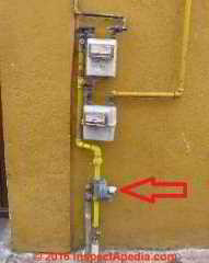
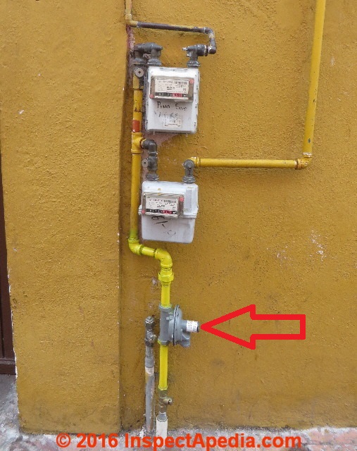
Page top photo: a single city gas service flowing through a first stage regulator (red arrow) and two gas meters at a city in central Mexico.
InspectAPedia tolerates no conflicts of interest. We have no relationship with advertisers, products, or services discussed at this website.
Gas Regulator Adjustment Procedure
 Watch out: improper installation and even improper inspection and testing methods involving natural or "LP" gas can involve
dangerous conditions and risk fire or explosion.
Watch out: improper installation and even improper inspection and testing methods involving natural or "LP" gas can involve
dangerous conditions and risk fire or explosion.
If you smell gas you should leave the building immediately and should do so without doing anything that could create a spark such as operating a light switch or telephone.
From a safe location, call your gas company's emergency line and/or your fire department.
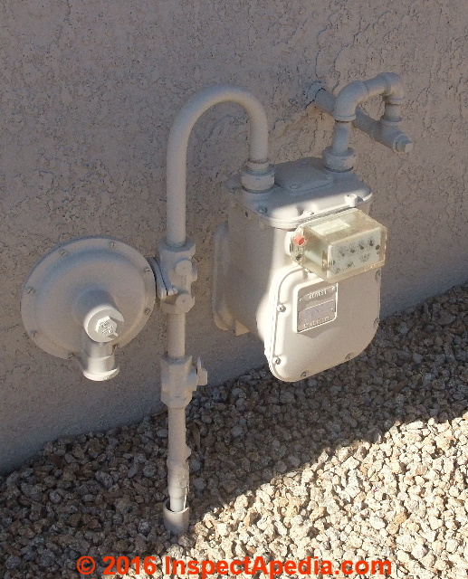
The gas regulator photograph shown at the top of this page and the regulator shown at left are examples of a first stage or primary gas pressure & flow regulator installed at both LP and piped-in natural gas installations world-wide.
The pressure and flow of gas through this regulator can be adjusted if the factory-settings are not adequate.
[Click to enlarge any image]
Reader Question: do I shut off the gas supply before opening up and adjusting a gas regulator?
2016/03/18 Angela said:
Light commercial application: After pulling the cap to a 2" gas regulator , what would cause the screw, retaining disc, and spring to pop out of a gas regulator from just touching the adjustment screw (not even beginning to adjust it)?
Would this indicate improper or unsafe gas pressure?
Also is it standard practice to shut off the gas supply before opening up and adjusting a gas regulator? Or is it standard practice to adjust it without doing so?
Reply:
I'm not sure, Angela; I've had similar problems on other plumbing components when a component stem, like a valve stem, was broken. But without question, if parts blow out of a gas regulator the situation is dangerous. It is possible that the regulator assembly is damaged and needs replacement.
I would be nervous about leaving such a device in service without help from an expert, on-site.
Typically on a gas regulator there are separate safety devices that will respond to over-pressure. We skipped you-tube DIY videos and other sources that looked risky or amateurish and went to the gas companies and the gas regulator manufacturers to see what they suggest.
Below we have adapted Lincoln Energy's gas regulator start-up and adjustment procedure for an Itron gas regulator along with additional details from Dormont, a major manufacturer of gas regulators.
Watch out: The outlet pressures of the adjustable regulators can be changed by removing the stem cap and adjusting the screw found inside.
Turning the screw counter clockwise reduces the outlet pressure, and turning it clockwise increases the outlet pressure.
Watch Out: Adjusting the outlet pressure should only be done while monitoring the pressure with a manometer or other type of pressure gauge.
Watch Out: Replace the stem cap when the adjustment is complete. - Dormont Manufacturing Co., document cited below.
Watch Out: the text below are excerpts only; the full instructions include other steps and other safety warnings - most jurisdictions require work be performed by a qualified, licensed professional: making a mistake can cause fire, explosion, death.
Start-up Procedure for a B-series Gas Regulator (all models)
To start-up the B-series regulator
- Mount a pressure gauge downstream of the regulator to monitor the downstream pressure.
- With the downstream pressure valve closed, slowly open the inlet valve. The outlet pressure should rise to slightly more than the set-point.
Note: For B31 RAS models, remove the seal cap and pull up on the spring housing stem to reset the shut-off valve.
Release the stem.
This procedure allows gas to flow through the regulator. - Downstream [gas] pressure should rise to the regulator's set-point.
- Verify there are no leaks and all connections are tight.
The regulator was pre-set at the factory to match order specifications. If necessary, adjust the outlet pressure by removing the seal cap on the top of the spring housing and rotating the adjustment screw inside the spring housing.
Note: Adjusting the outlet gas pressure requires:
Models 842, B57, B58, B31, B34S, B35, B56, and B36: large flat-head screwdriver
Models 834 and 838: 9116" socket and ratchet
Model RB4000: adjustment wrench (Itron part number 799056)
- With a small amount of gas flowing through the regulator:
Rotate the gas pressure regulator adjustment screw clockwise to raise the outlet pressure. - Rotate the adjustment screw counter-clockwise to lower the outlet pressure.
Note: It is recommended to monitor downstream pressure with a properly calibrated gauge per the chart below:
Downstream Pressure Monitoring for a B-series Gas Regulator1 |
||
| Gas Metering Pressure | Range of Gas Pressure Gauge | Increments of Gas Pressure Gauge |
| 6 inches water column (WC) | 0-12" WC or 0-30" WC | 0.1" or 1" WC |
| 14 inches water column | 0-30" WC | 1" WC |
| 55 inches water column = 2.0 psi | 0-100" WC | 2" WC |
| 10 psi | 0-15 # (psi) or 0-30 # (psi) | 0.1 psi or 0.2 psi |
Notes to the table above
1. Adapted from Lincoln Energy, 11919 W. I-70 Frontage Rd. North Unit #109 Wheat Ridge, Colorado 80033 USA. Tel: 303-697-6701. Details retrieved 2016/03/18, original source: www.lincenergysystems.com/linc-energy-blog/entry/how-to-install-a-natural-gas-pressure-regulator#.VuxQ_xIrIxg
Watch out:This data is for Itron gas regulators. Other gas pressures and adjustment procedures will be appropriate for other regulator types & applications.
Linc Energy Systems is a stocking distributor for Itron and services the following areas:
Colorado (CO), including: Boulder, Colorado Springs, Cortez, Denver, Durango, Grand Junction, Greeley, Pueblo, Rangely, Rifle, San Juan Basin, Steamboat Springs and Sterling Idaho (ID), including Boise, Idaho Falls, Mountain Home, Pocatello and Twin Falls Montana (MT), including: Billings, Bozeman, Kalispell, Missoula Western Nebraska (NE) Western North Dakota, including Bismark Western South Dakota, including Rapid City Utah (UT), including Centerville, Murray, Ogden, Provo, St. George, Salt Lake City, Vernal Wyoming (WY), including: Big Piney, Casper, Cheyenne, Cody Evanston, Evansville, Gillette, La Barge, Laramie, Rawlings, Rock Springs and Sheridan. More information is available on Itron's regulators at the contact information we give just below.
2. Itron Inc. Gas Regulator Company, 2111 North Molter Road, Liberty Lake, WA 99019-9469 USA Tel:: (509) 924-9900 Website: https://www.itron.com
3. "Dormont Gas Appliance & Line Pressure Regulators" [PDF], Dormont Gas Regulator Company, 6015 Enterprise Drive, Export, PA 15632 USA, Tel: (724) 733-4800 / 1-800-DORMONT (367-6668) Website: www.dormont.com
This document includes a Gas Flow Capacities Table that tabulates gas regulator operating inlet pressure (between 1/2 psi and 2 psi for the Dormont regulators discussed) and outlet gas pressure in inches of water column for various total input BTUs/hour requirements for all of the gas appliances being served through an single primary regulator.
Excerpts from the Dormont Gas Regulator product specifications document above:
Dormont Manufacturing, the inventor and world’s largest manufacturer of stainless steel gas connectors, introduces an expanded line of 2 psig regulators for Natural and Liquified Propane Gases. Our CSA design certified R325 and R625 Series pressure regulators are manufactured as gas appliance regulators, and as line pressure regulators.
Both series supply precise regulating control from full-flow, down to tiny pilot flows. In the absence of flow, these regulators guarantee excellent control of the outlet pressure. The R325 and R625 Series regulators meet standard requirements for use on residential, commercial, and industrial applications.
Regulators are factory pre-set at 8'' w.c. for natural gas and 11'' w.c. for propane.
4. ANSI Z21.80, CGA 6.22, Gas Line Pressure Regulators, available at webstore.ansi.org
Abstract:
Details test and examination criteria for line pressure regulators, either individual or in combination with over pressure protection devices intended for application in natural gas piping systems between the service regulator and the gas appliance(s).
This standard applies to regulators rated at 2, 5, or 10 psi (13.8, 34.5, or 68.9 kPa) with maximum outlet pressure of ╜or 2 psi (3.5 or 13.8 kPa), depending on the intended application.
5. ANSI Z21.18-2007/CSA 6.3-2007 (2012) - Gas Appliance Pressure Regulators, available at webstore.ansi.org
Abstract:
This publication represents a basic standard for safe operation, substantial and durable construction, and acceptable performance of gas appliance pressure regulators. It is the result of years of experience in the manufacture, testing, installation, maintenance, inspection and research on gas appliance pressure regulators designed for utilization of gas.
There are risks of injury to persons inherent in appliances that, if completely eliminated, would defeat the utility of the appliance. The provisions in this standard are intended to help reduce such risks while retaining the normal operation of the appliance.
- Replace the seal cap and check for leaks after the desired outlet pressure is achieved.
The gas regulator is ready for operation.
How to Convert Typical Gas Appliance Regulator Pressure from PSI to Inches of Water or WC
| Typical Gas Appliance Regulator Pressure in PSI = Inches of Water or WC | ||
| Pressure in PSIG | Pressure inches of Water Column |
Example Regulator Comment |
| 0.0360912 | 1 in. WC | |
| 0.0721824 | 2 in. WC | |
| 0.108274 | 3 in. WC | |
| 0.144365 psi | 4 in. WC | |
| 0.180456 psi | 5 in. WC | |
| 0.216547 | 6 in. WC | |
| 0.252638 | 7 in. WC | |
| 0.28873 | 8 in. WC | |
| 0.324821 | 9 in. WC | |
| 0.324821 | 10 in. WC | |
| 0.500000 | 13.8538 | Outside the range of typical residential gas appliances |
| 1.00000 | 27.7076 | Outside the range of typical residential gas appliances |
Notes to the table above
PSIG or PSI = pounds of pressure per square inch (gauge pressure)
WC or "WC = equivalent pressure expressed as inches of water column
Typical gas appliance regulators are rated at 1/2 psig input; adjustable regulators can be set to a range of output pressures measured in in. WC.
Gas Regulator Operating Details
Below we illustrate and discuss the typical components of a gas regulator, adapting a schematic from Dormont Gas Regulator Company, cited above.
This illustration and text explain why adjusting a screw in the gas regulator top will change the flow rate and pressure of gas delivered to the building by the regulator.
Gas from the supply (natural gas pipe or LP gas tank) enters the regulator at the inlet end (A). When no appliance in the building is using gas and thus no gas is flowing in the building, gas pressure passing through the valve seat builds up gas pressure in the regulator body (the light yellow area in the center of the valve).
The gas inside the regulator body presses upwards on the regulator diaphragm (B) that in turn presses against the regulator spring (C).
As the diaphragm rod and assembly moves up, the hinged balancing spindle assembly (D and E) closes the valve seat.
In effect this means that when no gas flow is demanded inside the building, the regulator "shuts off" gas flow at the valve seat in the inlet port.
![Gas regulator schematic adapted from Dormont Gas Regulator specifications, Dormont Gas Appliance & Line Pressure Regulators [PDF], Dormont Gas Regulator Company, 6015 Enterprise Drive, Export, PA 15632 USA, Tel: (724) 733-4800 / 1-800-DORMONT (367-6668) Website: www.dormont.com](Dormont_Gas_Regulator_Schematic.jpg)
When local appliance-regulator at a gas appliance in the building opens to begin to consume gas, gas inside the regulator flows outwards at the right end of the regulator (yellow arrow in the right of the illustration above).
This flow out of the regulator causes gas pressure in the regulator to drop, thus reducing gas pressure against the rubber diaphragm and spring, allowing the spring to push the diaphragm downwards, opening the gas valve at the valve seat on the gas inlet end of the regulator. The open valve thus allows more gas from the supply source to enter the regulator.
Spring pressure at the Dormont regulators illustrrated here are pre-set at the factory to 8" WC for natural gas and 11" WC for propane gas.
Adjusting the spring on the regulator is adjusting the gas regulator's outlet gas pressure. When the spring can push the diaphragm down it opens the gas regulator allowing gas to flow. Therefore if we increase the spring pressure we are allowing more gas to flow (higher pressure and flow rate).
For the Dormont gas regulator type shown, turning the regulator adjustment screw counter-clockwise reduces the outlet gas pressure while turning the adjustment screw clockwise increases the outlet pressure. (That's because turning the screw clockwise also increases the spring pressure against the diaphram.)
Gas Regulator Vent Limiting Device
Gas regulators include a vent limiting device that controls the rate of escape of gas from the regulator in the event that the diaphragm in the regulator should rupture or tear.
You can see the vent limiting device on Dormont's gas regulator at the upper right side of the regulator in the illustration above.
Here is how Dormont explains the vent limiter on their regulator:
In the event of a diaphragm rupture, the vent limiting device limits the escapement of gas within the ANSI standards level, thus eliminating the need to run vent piping to an outside area.
If a vent pipe to the outside is desired, the vent limiter may be removed and a vent pipe with proper pipe threads can be substituted.
Warning: Do not operate the regulator without either a vent limiter or a vent pipe to the outside. A vent limiting device is standard with all Dormont R325 and R625 Series regulators. - Dormont, op. cit.
Typical LP Gas, Propane Gas, or Natural Gas Pressures in Residential Systems
 LP Gas or Propane Pressures:
- 10-200 psi in the LP gas storage tank
- 0.4 psi at typical residential appliances
Natural Gas pressures:
- Natural gas in the natural gas service line in the street will be found at pressures from 60 psi down to as low as 0.25 psi.
- At individual natural gas appliances the gas pressure will be regulated to about 0.25 psi [1]
Details about the different pressures found or set for LP gas, propane, and natural gas including before and after different gas pressure regulators are
at GAS PRESSURES LP vs NATURAL GAS
Adjustable Output Gas Appliance Regulators
 Question: is it OK to use a 4" WC appliance regulator on a 5"WC appliance?
Hi, apologies if this is a double post, I tried posting yesterday but not sure that post made it through to you.
I am installing a used Jennair natural gas cooktop unit in my kitchen, replacing an existing unknown brand unit.
I realized too late that the Jennair unit does not include the pressure regulator.
I am trying to determine whether it is safe to use the regulator from the unit I am replacing.
Jennair customer support refused to provide any information re: the regulator requirements for their now-discontinued unit (model CCG556), nor any suggested replacement for their now-discontinued OEM regulator (part #Y04100307).
I located a Jennair service manual for this model online, it indicates 5" WC output from the OEM regulator.
The regulator I have from the unit I am replacing indicates 4" WC output to the appliance.
Can you tell me whether this is safe to use, and if not, can you suggest a replacement regulator? I hooked up the Jennair using the 4" WC output regulator I have for a trial run and everything appears to be working fine, with no leaks. But I realize the "gas goes BOOM" caution that is required here so just want to be as safe as possible.
Thanks. --Allen
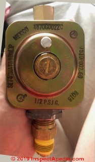
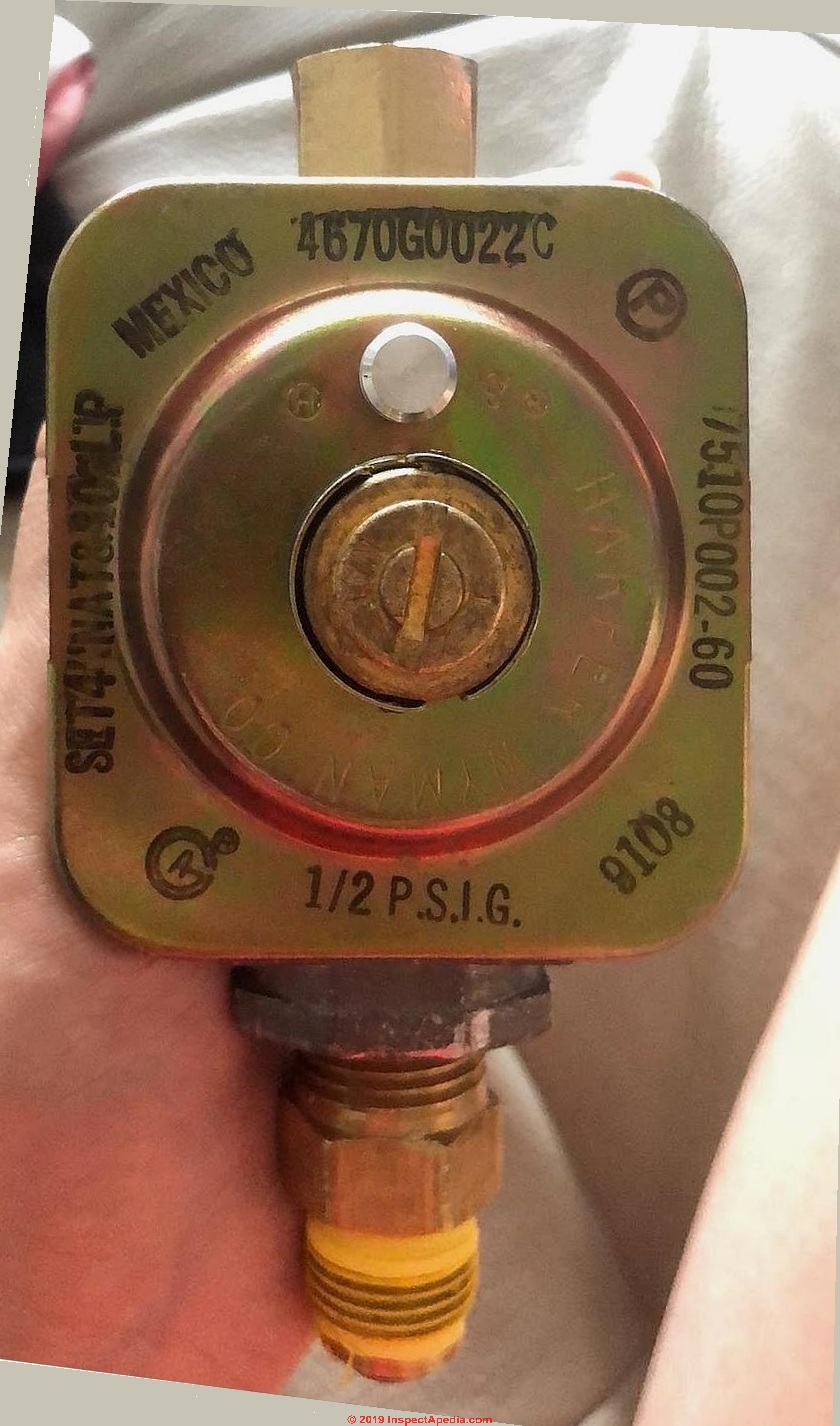
(see attached picture [above] of the regulator I have that was serving the cooktop unit I am replacing).
This Q&A were posted originally at GAS REGULATORS & APPLIANCE / HEATER CONTROLS - home and also in a more brief posting that appeared first at GAS REGULATORS for APPLIANCES FAQs
Reply:
Let me answer your question again here in more exquisite detail.
Your gas regulator photo posted [above] illustrates a Harper Wyman Co. gas appliance regulator rated for 1/2" psig and providing 4" W.C. output for natural gas & 10" LPG. It might in fact be adjustable up to 5" W.C. - to find out for sure you'd need to contact Harper Wyman with the model information on your regulator.
You said that you asked the Jennair, the cooktop manufacturer, about buying a regulator for a used, now obsolete gas cooktop and you explained that they were not helpful: you said that you were told to buy a new gas cooktop.
 I suggested that you might find a third party gas appliance regulator that provides the required 5" WC and adequate flow that the older cooktop needs.
Watch out: I said (somewhere in InspectApedia.com's abyss) that PROVIDED you have no gas leaks and proper installation of all parts etc. the remaining risk is less a BOOM as you put it and more that the flame size is too low when the burner is fully open or that the flame is unstable (the latter would be unsafe).
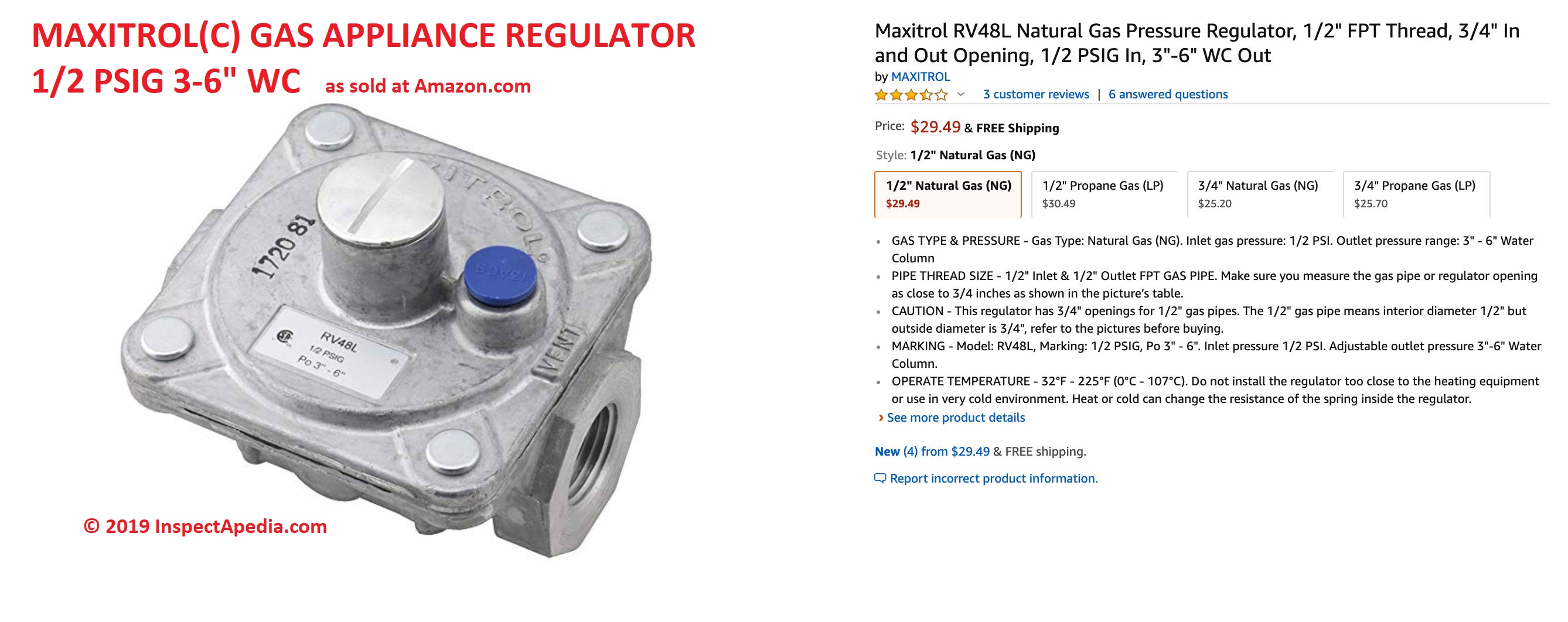
Gas appliance regulators are sold online by many vendors at prices from about $15. U.S. to $50. U.S. - often for the very same device.
Some of them have adjustable flow rates or pressures that can step up from 4" to 5" WC.
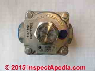
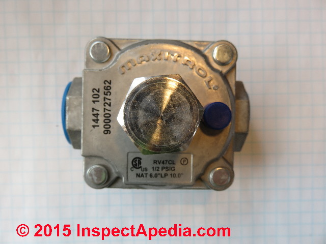
Take a look at the adjustment range of the Maxitrol gas regulator shown here: My red arrow points to a key data tag on the regulator, indicating that this model is rated 1/2 PSIG. This is a typical gas appliance regulator that can be set brom 3 to 6" WC [for natural gas] or an equivalent higher output pressure for LPG.
Other Maxitrol gas regulators operate at different "W.C. pressures depending on the model, and other features are available too.
Watch out: also be sure you've got the regulator set for the right fuel - LPG or Natural Gas. Most are convertible.
Details about LP gas pressure vs natural gas pressures are
at GAS PRESSURES LP vs NATURAL GAS
The conversion procedure between the two fuels is discussed separately
at GAS APPLIANCE CONVERT REGULATOR NATURAL GAS-to-LP
Gas appliance regulators are made in the millions, and are used widely across many appliances - you can meet the specification for your Jennair gas cooktop without having to get the regulator ONLY from the manufacturer who, as you can guess, are often in fact buying their regulators from a third party anyway.
Watch out: Yes a gas leak or gas explosion can kill you and everybody nearby, burn down the house, and hurt a lot. If you or another reader are not qualified and expert in gas piping and appliance installation you should have the installation made by someone who is.
One can imagine that the manufacturer's person answering the phone has been told that only ZERO LIABILITY is acceptable. The manufacturer doesn't want to kill their customers. And the Jennair rep has no idea how expert and safe you or your work might be. That might explain why the Jennair person was not more helpful.
It's like those signs on dump trucks that used-to but no longer read "Keep Back 600 feet" - instead they now read "DO NOT FOLLOW" = in other words turn around and go home. Get off the highway.
As someone who works in a law office you can understand this. You fellows write those warnings and instruct those technicians at Jennair.
Check out OTHER PEOPLE's MONEY for an eloquent exposition on why some consultants, attorneys, and others give such cautious advice - they're not looking out just for you.
I worry about our readers too - but not foremostd about getting sued (as I don't have anything) but rather about a reader who kills themselves or someone else by not recognizing what they don't know or what is unsafe.
Gas Appliance Regulator Instruction Manuals & Data Sheets
- AIHA: faulty gas regulator causes explosion: https://www.aiha.org/get-involved/VolunteerGroups/LabHSCommittee/Pages/Faulty-Gas-Cylinder-Regulator-Causes-Explosion.aspx
- Beswick gas regulators: basic information http://www.beswick.com/sites/dev.beswick.com/files/Basics%20of%20Pressure%20Regulator.pdf
- Emerson gas regulators: http://www.documentation.emersonprocess.com/groups/public/documents/bulletins/d450144t012.pdf discusses inspecting the regulator for damage
- Harper-Wyman GAS REGULATOR CONVERSION INSTRUCTIONS [PDF] Harper-Wyman Company, Subsidiary of Oak Industries, Inc., 3600 Thayer Court, Suite 110, Aurora IL 60504 USA, Tel: 708-978-8000
See pp. 5-6 describing converting a Harper-Wyman gas regulator between LP gas and Natural gas, in these instructions for the Thermador Professional Pro dual-fuel gas ranges. These gas regulator conversion instructions pertain to other appliances as well. - Maxitrol GAS PRESSURE REGULATORS CATALOG 3rd Ed. [PDF], (2017) Maxitrol Company 23555 Telegraph Rd., PO Box 2230 Southfield, MI 48037-2230 USA, Website: www.maxitrol.com
- Maxitrol GAS APPLIANCE REGULATOR MODEL CODE KEY [PDF] (2015) Op. Cit.
- Maxitrol POPPET GAS REGULATORS [PDF] Op. Cit.
- GAS APPLIANCE REGULATOR SPECIFICATION & SAFETY INTERPRETATION [PDF] (2010, 11/18) US DOT, Pipeline and Hazardous Materials Safety Administration, 1200 New Jersey Ave SE, Washington DC 20590, letter to Michael H. Kyle, B. Knight Natural Gas Servicves, PO Box 5702, Midlothian VA 23112
- Zafer, Naci, and Greg R. Luecke. "Stability of gas pressure regulators." Applied Mathematical Modelling 32, no. 1 (2008): 61-82.
Reader Comments, Questions & Answers About The Article Above
Below you will find questions and answers previously posted on this page at its page bottom reader comment box.
Reader Q&A - also see RECOMMENDED ARTICLES & FAQs
On 2020-12-07 by (mod) - suddenly a yellow flame on our natural gas appliances
Bob
Yellow gas flame often means that there's a lack of combustion air or that the burner is out of adjustment.
Watch out: when the flame is not burning correctly it's possible that the heater is producing dangerous even fatal carbon monoxide.
Be sure that you have working carbon monoxide detectors properly located and tested in your home.
With that safety measure in place, you can look more closely at your heater to see if it's producing soot, or if there's a blocked chimney or if someone has closed off its combustion Air Supply.
If you don't see something obvious, you may call a heating service technician to examine the system.
The adjustment is not normally done at the gas meter. More likely it's a burner, venting, or combustion air problem.
On 2020-12-06 by bob
We are suddenly getting a yellow flame on our natural gas appliances to wit kitchen range, fireplace, & fire table. Does this require can adjustment at the meter?
On 2020-08-26 by bob baldwin
I had a perfectly operating propane system for my home. I had a propane pool heater installed and when the contractor made the connection in front of my second stage regulator and turned on the gas, the regulator failed and began dumping propane out of the vent. They had to shut the gas off to my home.
They said there is nothing they could have done to make it fail but common sense says they are wrong.
Can someone tell me what they could have done to damage the regulator please. Did send to much pressure to fast when turning back on the gas? .Thanks
On 2019-02-25 - by (mod) -
 The green dot tells you which line is sending fuel to the regulator. So when the green dot is towards the left-hand propane feed line the tank connected to that line is being fed to the LPG regulator, and conversely when the green dot is rotated towards the right the right-hand copper propane feed line is bringing LPG from the tank to which that line connects.
you will notice that in addition to the green dot there is an arrow molded into the black cap that's probably intended to be a pointer indicating the active propane feed.
On some LPG controls, a yellow indicator on a propane tank level gauge or possibly that yellow dot in the center of your LP gas switchover valve indicates low propane level or low fuel.
Take a closer look around the metal parts of the changeover valve and cap and post a couple of images of the text - that'll help me find the exact LP tank valve brand and model.
You might also give your LP delivery company a call.
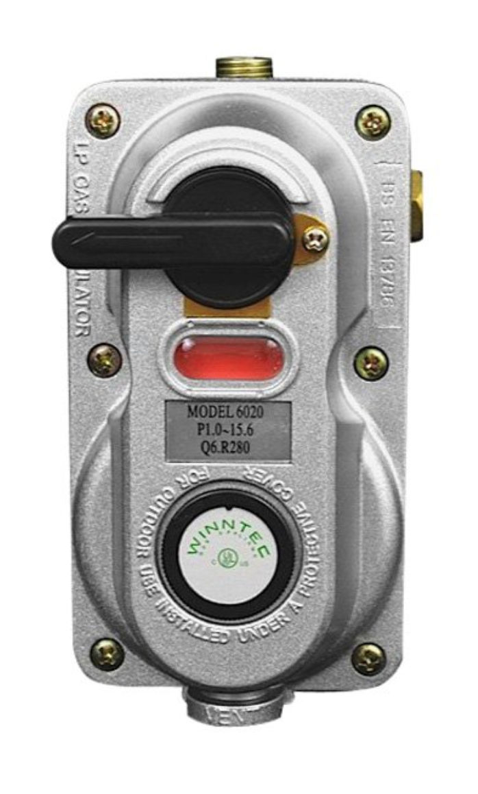
Shown here is another example of an LP gas tank switch-over valve, the Enerco F173766 Propane Auto Changeover Two Stage Regulator Clamshell
by ENERCO TECH and sold by plumbing suppliers, building suppliers, and online at Amazon.
On 2019-02-25 by Diane
Can you tell me what this LPG changeover regulator is indicating? Attached to 2x 45kg cylinders. How will the dial look when one bottle empties?
IMAGE LOST by older version of Clark Van Oyen’s Comments Box code - now fixed. Please re-post the image if you can. Sorry. Mod.
On 2018-12-12 by Carl D. - burner ignition problem at just one gas appliance
I have a propane problem that is baffling technicians from three different companies. I live in an old house in Wisconsin with three propane appliances. The wall heater and hot water heater on the first story have never been a problem.
It is the wall heater on the second story that keeps having problems. I replaced it 8 years ago when the old one (which had been there for at least 50 years with no problems) started with the same problem, which is an ignition/burner issue.
The problem starts at ignition sometimes, or else some seconds after a normal ignition. It sounds as if the gas is being constricted. I quickly turn down the thermostat to stop the burning, and if I then immediately turn it back up, it ignites and burns properly.
I obviously can't be there all the time to manually control it. But perhaps the biggest puzzle is that it only does this about 90% of the time, and of course I can't make it do it for diagnosis.
Technicians have checked the pressure at the heater, and the tech from my propane company checked the regulators on the propane tank and on the house. They were installed in 2005.
The heater is the farthest from the regulator of the three appliances (about 18 feet), but the technicians checked their manuals and the piping should be able to handle it.
The problem didn't occur in the new heater until it was 3 or 4 years old. The intermittent, random nature of the problem is stumping everyone. I'm wondering if a regulator could act in such a way.
Since it's located outside, and it has metal parts in it, could temperature be playing a role? I'm also wondering about the purity of the propane.
Many thanks for any light you can shed on this!!
Carl D.
On 2017-10-30 - by (mod) -
Wayne posted a link (removed for security) to the sale at Amazon of a Robinair 42160 Gas Manifold Pressure Test Kit, 0-35" Water Column
On 2017-10-29 by Gerard
Hi All, We are looking for an inline measuring device with readout to determine LP flow through to our burner to specify rate of consumption ? Any idea of where to buy such a device or the best device for this application?
On 2016-10-22 - by (mod) -
Luis, I don't know what equipment or system you are working-on, but I agree that 7.5" WC outlet pressure from a regulator is within a 9-13" of water column setting range.
On 2016-10-22 by luis
inlet pressure are 18 psi in Fisher R22 outlet pressure are 7.5 water column is that correct ? the label read is 9-13 water column outlet pressure
On 2016-04-13 - by (mod) -
Greg:
The procedures I've read call for the gas valve to the appliance in the open position - so we're testing that the appliance's own shutoffs also work without leakage; but appliance in-operation was not cited.
Because the gas regulator is designed to keep a constant pressure in the system when demand varies (for example when a second gas appliance on a circuit fires-up), I would expect the gas pressure to remain close to constant regardless of whether the appliance is on or off.
However when we are doing LEAK TESTING we want the appliance OFF, since we want to know that the appliance valve isn 't itself leaking when closed.
On 2016-04-13 by Greg
In a gas fired heating system, is the gas pressure going to the unit (~7 inches water) measured in a static condition or dynamic condition (gas flowing)? What is typically the difference in pressure between those readings?
...
Continue reading at GAS REGULATORS & APPLIANCE / HEATER CONTROLS - How to find & report defects found in LP or natural gas regulators or controls. Gas regulator inspection, diagnosis, and repair guide, or select a topic from the closely-related articles below, or see the complete ARTICLE INDEX.
Or see these
Gas Regulator Articles
- GAS REGULATORS & APPLIANCE / HEATER CONTROLS - home
- GAS APPLIANCE CONVERT LP-to-NATURAL GAS
- GAS APPLIANCE CONVERT REGULATOR NATURAL GAS-to-LP
- GAS APPLIANCE OPERATION at HIGH ALTITUDE
- GAS COOKTOP INSTALLATION
- GAS COOKTOP RANGE & OVEN REPAIR & MANUALS
- GAS PRESSURES LP vs NATURAL GAS
- GAS REGULATOR ADJUSTMENT PROCEDURE
- GAS REGULATOR CONVERSION NG-LP
- GAS REGULATORS for LP TANKS
- GAS REGULATOR NOISES
- GAS REGULATOR TEST PROCEDURES
- GAS REGULATORS, TWO STAGE
- MERCURY HAZARDS in APPLIANCES & GAS REGULATORS
Suggested citation for this web page
GAS REGULATOR ADJUSTMENT PROCEDURE at InspectApedia.com - online encyclopedia of building & environmental inspection, testing, diagnosis, repair, & problem prevention advice.
Or see this
INDEX to RELATED ARTICLES: ARTICLE INDEX to GAS APPLIANCES, PIPING, CONTROLS
Or use the SEARCH BOX found below to Ask a Question or Search InspectApedia
Ask a Question or Search InspectApedia
Questions & answers or comments about inspecting, diagnosing, repairing, or replacing LP gas regulators and Natural Gas regulators found on heating appliances
Try the search box just below, or if you prefer, post a question or comment in the Comments box below and we will respond promptly.
Search the InspectApedia website
Note: appearance of your Comment below may be delayed: if your comment contains an image, photograph, web link, or text that looks to the software as if it might be a web link, your posting will appear after it has been approved by a moderator. Apologies for the delay.
Only one image can be added per comment but you can post as many comments, and therefore images, as you like.
You will not receive a notification when a response to your question has been posted.
Please bookmark this page to make it easy for you to check back for our response.
Our Comment Box is provided by Countable Web Productions countable.ca
Citations & References
In addition to any citations in the article above, a full list is available on request.
- National Fuel Gas Code, ANSI Z223.1-yyyy - American Gas Association / National Fire Protection Association
- LP-Gas Serviceman's Handbook,Fisher-Rosemount, Fisher Controls
- National Fire Protection Association (NFPA) Pamphlets No. 54 and 58.
- Specifications for Gas Installations, Central Hudson Gas and Electric Corporation
- "Gaslight", Gary Quilliam, The Old House Journal, March/April 1989 article describes fixtures, modern fixtures, and sources of supply.
- Residential Gas Hot Water Heater Pocket Partner - Testing and Trouble Shooting, 19. State Corp., Ashland City, TN 37015
- Carbon Monoxide Gas Toxicity, exposure limits, poisoning symptoms, and inspecting buildings for CO hazards
- HOT WATER HEATERS - a detailed guide to all types of hot water sources, problems, inspection, repair
- SEWER GAS ODORS in COLD / WET WEATHER - Septic Odors or Sewage Odor Diagnosis & Repair Guide for diagnosing and eliminating cold weather sewer gas odors
- Water Pressure Loss - Diagnosis how to determine why water pressure has been lost or why there is no water at all in a building
- In addition to citations & references found in this article, see the research citations given at the end of the related articles found at our suggested
CONTINUE READING or RECOMMENDED ARTICLES.
- Carson, Dunlop & Associates Ltd., 120 Carlton Street Suite 407, Toronto ON M5A 4K2. Tel: (416) 964-9415 1-800-268-7070 Email: info@carsondunlop.com. Alan Carson is a past president of ASHI, the American Society of Home Inspectors.
Thanks to Alan Carson and Bob Dunlop, for permission for InspectAPedia to use text excerpts from The HOME REFERENCE BOOK - the Encyclopedia of Homes and to use illustrations from The ILLUSTRATED HOME .
Carson Dunlop Associates provides extensive home inspection education and report writing material. In gratitude we provide links to tsome Carson Dunlop Associates products and services.
 | HOME | ABOUT | ASK a QUESTION | CONTACT | CONTENT USE POLICY | DESCRIPTION | POLICIES | PRIVACY | |
| © 2024 - 1985 Publisher InspectApedia.com - Daniel Friedman | |||||||||