
InspectAPedia® FREE Encyclopedia of Building & Environmental Construction, Diagnosis, Maintenance & Repair |
Question? Just ask us! InspectAPedia
|
 Drain Back Valve & Snifter Valve Components & Definitions
Explanation of bleed-back valves, drain back valves, snifter valves & AVCs used with bladderless water tanks & a well or lake water supply
- POST a QUESTION or COMMENT about sifter valves, Dill valves, and how the snifter valve works together with US Gauge & Similar Type 310WJ, Type 300SL, or Type 6 Rectangular Air Volume Controls
Definition of Drain Back Valves, Bleed-Back Systems & Snifter Valve Components & Air Volume Controls:
This article defines drain back valve or bleed-back val and the , snifter valve and describes how these components work to protect water pipes from freezing by allowing water to drain out at the end of a water pump cycle. These same components, working with an air volume control valve on the water tank also keep the proper air charge in the tank, avoiding well pump rapid on-off cycling.
We describe how & where the snifter valve, drainback valve and air volume control are installed & what they look like.
Snifter valves & drain-back valves along with AVCs are a three-part air volume control system designed to allow water to drain out of well piping and back into the well while also maintaining water pressure in the building and the air charge in a well water pressure tank.
InspectAPedia tolerates no conflicts of interest. We have no relationship with advertisers, products, or services discussed at this website.
Drain Back Valve, Dill Valve, & Snifter Valve Components, Definitions & Functions
 Drain-Back System for Well Pipe Freeze Protection
This well pipe freeze protection system has multiple components that work together to get water out of well pipes that might otherwise freeze.
- A bladderless water pressure tank fed, along with the building water supply piping by
- A submersible well pump water (the pump is located in the well)
- An air volume control or AVC serving as an air outlet on the bladderless water tank,
working with two drain-back system components:
- An air inlet, the snifter valve that allows air into the well piping when the pump stops, and
- A water outlet, the drain back valve that lets water drain out of the well piping when the pump stops..
These devices are used on some submersible pump systems in wells or in lake water supply systems where a bladderless water tank is installed and where well piping is exposed to freezing. By allowing water to drain back out of the portion of well piping that is exposed to freezing, the water supply system can continue to function during freezing weather.
Below we expand and illustrate these definitions in more detail and with some photos of each device
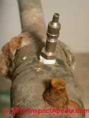
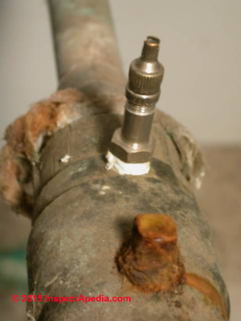
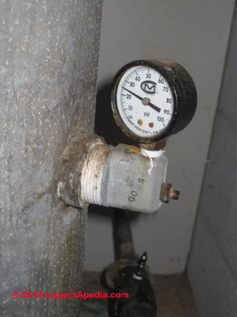
- A Snifter Valve (or Schrader type air valve) is the well piping air inlet that allows air to enter the well piping from a check valve mounted on the well side of the water pressure tank.
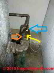
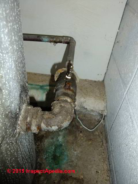
In our photo above the blue arrow points to the snifter valve - an air admittance device. It's partner, the AVC or air Volume Control (immediately below) is on the water pressure tank side, and the drain-back valve, shown further below on this page, is located on vertical well piping inside the well.
[Click to enlarge any image]
- An air volume control or AVC (photo just above) mounted mid-height on the water pressure tank (photo above) keeps the proper level of air in the pressure tank by releasing excess air until rising water in the pressure tank closes the AVC vent.
That's why we may hear hissing at the mid-tank AVC on some water systems.
 ...
... 
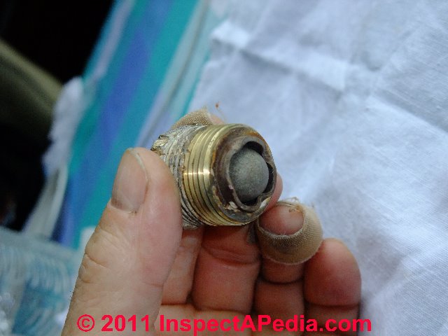
- A Drain Back Valve (photos just above) mounted on a tee on the well piping and shown in our photos later on this page is a water outlet on the well piping inside the well.
Air enters at the snifter valve above ground and water exits the well piping inside the well at the drain-back valve.
Observing and working with a Minnesota well drilling company in Two Harbors we were told that the Snifter Valve's job was to keep an air charge in the pressure tank by admitting air into the well piping at the end of each pump on-off cycle.
Definition of the Air Volume Control (AVC) & Its Functions
Click to enlarge any image]
The AVC is operated by a float that is in turn operated by the water level in the pressure tank to open or close the AVC properly.
The pressure tank used on drain-back water supply systems is normally a steel or fiberglass water tank that does not make use of an internal bladder to keep water and air in the tank separate.
At each pump-on cycle, air in the water piping is pushed back up into the water pressure tank. This air volume (inside all of that well piping) is more than is needed in the pressure tank to prevent short cycling of the water pump. The excess air volume in the tank would then result in air discharge at the building's plumbing fixtures.
So an automatic air volume control (AVC) mounted into a tapping (or "tank bung") at the middle of the water tank's height is designed to vent excess air from the water tank.
Our photo shows the air volume control. The AVC float mechanisms inside the tank where it rises or falls according to the water level in the pressure tank. The float opens (on water level fall) the air vent on this AVC to vent excess air in the pressure tank. When water in the tank reaches a little below the level of the AVC valve itself, the float closes the vent to stop releasing air from the tank, keeping the proper air charge in this bladderless pressure tank.
See WATER TANK AIR VOLUME CONTROLS for more about these devices.
If the AVC is not working properly on non drain-down systems you may find a water-logged pressure tank causing well pump is short cycling.
See WATER PUMP SHORT CYCLING
But if an AVC is not working on a drain down system or you will find air discharge at the building's faucets.
See AIR DISCHARGE at FAUCETS, FIXTURES
Definition of Bleed-back Valve or Drain-Back Valve & Its Functions
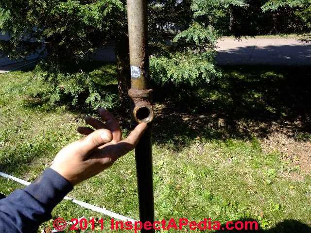
The drain back valve is installed on a tee on the vertical well piping, (photo above) making it a device that you won't see unless you're paying attention while a well pipe and submersible pump are being installed-in or removed from a well bore or casing.
This device is used to allow air to enter the well piping between the drain-back valve tee and the building water tank at the end of each pump-on cycle.
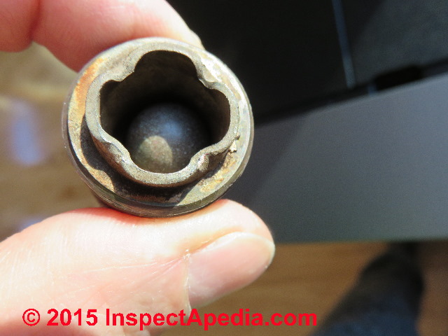
The drain back valve opens when the submersible pump stops and pressure in the well piping drops. At that point a ball inside the snifter valve moves towards the well piping center (away from the outer face or air vent in the valve).
This allows air to enter through a small opening in the snifter valve. With no foot valve or check valve on the bottom of the well piping, admitting air into the vertical well pipe allows water to flow out of the well pipe bottom and back into the well.
The result is that as long as the drain-back valve itself is located below the frost level, water in the well piping above the valve will drain back into the well, leaving the well piping empty of water and full of air. (No, this scheme is not a lot of hot air.)
At above left the internal ball that forms the valve inside this drain-back valve is away from the small1/8" opening on the face of the drain-back valve: a position that occurs when pressure drops in the well piping (the pump has shut off) and one that permits water in the piping above this point to exit through the small drain back valve orifice.
Water drains out of the well piping and back into the well casing through the drain-back device.
Note that water exits at the drain back valve only because the snifter valve, located above-ground and normally at the water pressure tank, is allowing air to enter the well piping at that point.
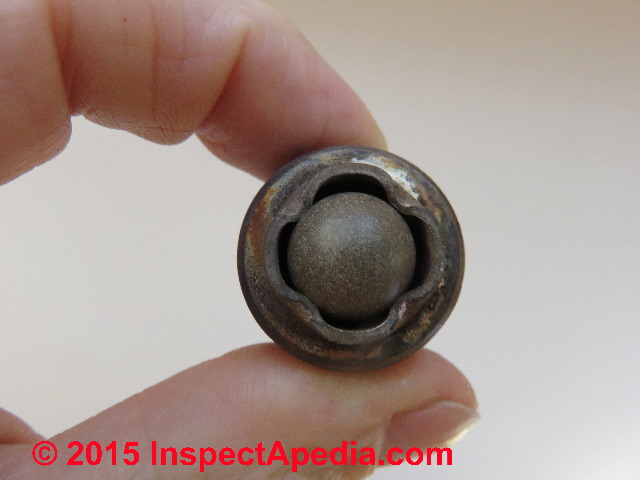
You can see the drain back vent's ball pushed into the valve body in our second photo - above right. In this position the small water outlet orifice is closed, preventing water from squirting out of the drain back vent's air opening while the well pump is running.
If the water outlet vent fails to close when the submersible pump is running, some water pressure, quantity, and flow delivery to the building will be lost.
Special thanks to reader Dave for helping clarify the text above (12/2020) - Ed.
Details of exactly how to install a snifter valve and a drain-back valve are
at DRAIN BACK & SNIFTER VALVE INSTALLATION / REPLACEMENT
Explanation of Snifter Valve & Its Functions
with submersible well pumps & bladderless water pressure tanks
A special Schrader valve [it looks like the air valve on a tire], the snifter valve, also referred to as a Brady air vent valve basically a one-way valve that allows some air into the well piping system at the end of a pump cycle but prevents water from exiting the piping system (at the snifter valve) when the the pump is running and the well piping is pressurized with water.
This special schrader valve, referred to as the "snifter valve" allows additional air into the well line to allow well piping water to drain back into the well.
The snifter valve looks like a tire valve or air valve and is mounted on an 1/8" tapping on a check valve typically at or close to the bottom of a steel bladderless water pressure tank.
The snifter valve works in concert with a drain-back valve and an air volume control valve as part of a triumvirate of air admittance and air volume control used with submersible well pumps installed in areas where shallow well piping is at risk of freezing.
Why doesn't the snifter valve also allow drain-back of all of the water in the pressure tank too?
A check valve is located at the point where the well piping enters the bottom of the water pressure tank. This valve keeps water from leaving the pressure tank in an attempt to head back into the well each time the pump stops.
More about how each of these components works is
at DRAIN BACK & SNIFTER VALVE OPERATION
If you're not sure how check valves work or where they are needed on water and well piping systems
see CHECK VALVES, WATER SUPPLY, DRAINS, PUMPS
This article series describes snifter valves and drain-back valve , what they are, how they regulate air in a well water system, how they work with an air volume control,& how these components protect well piping against freezing. We describe how & where the snifter valve, drainback valve and air volume control are installed & what they look like.
Reader Comments & Q&A
Question: snifter valve air volume control systems can remove iron and sulphur from water?
(Jan 22, 2014) joe said:
Hello I am writing about the snifter valve. If you read your article on why are snifter valve air volume control systems used one it states that the high absorption of air into the system helps oxidize and thus reduce hydrogen sulfide or perhaps iron.
But in your last email to me you said it would not. So you have me confused. Thanks for your reply. JOE
Reply:
Thanks so much Joe, I will review these articles and fix that inconsistency.
Honestly, I am sure that I added the statement to which you refer while I was reviewing research about snifter valves, but in replying to your email I simply forgot about it.
You were right, I was mistaken. However we need some clarification:
A snifter valve is only used on deep wells that are operated by a submersible pump AND that feed water into an older-style bladderless expansion tank.
The snifter valve, installed in the well piping lets air into the system at each pump on cycle. A companion vent valve installed above ground, close to the pressure tank, or in some cases ON the pressure tank, vents excess air out of the tank to keep the tank's air charge at the proper level.
A water supply system that uses a "captive air" type water pressure tank that incorporates an internal bladder does not need this automatic injection of make-up air, so will not have a snifter valve. In fact when a plumber converts a water supply system from bladderless-tank to internal-bladder tank, s/he needs to also pull the well piping and remove the old snifter valve if one was installed. That is what was going on in my photo series about snifter valves.
So if your water system uses a bladder type tank you wouldn't have a snifter valve installed.
Finally, and here is where we need to do more research, despite the claims of the snifter valve camp, I am doubtful that air injection ALONE will cure a serious sulphur odor in the water supply. More likely we'll need to install a treatment system such as a potassium permanganate "green sand as the plumbers call it" system or a chlorine injection system, combined with filtration, or some equivalent.
Do keep me posted, and thank you VERY much for helping me out with clarity and pointing out an inconsistency on this topic.
Question: to drain the water line I should open the cap on the snifter valve?
(Oct 13, 2014) Ray said:
I recently had a new well installed, drilled w/ a submergible pump. a internal bladder tank was installed .
I was concerned about the water in the tank and water line freezing in the winter , so a sniffer valve was installed on the the check valve.
I was told when shutting the system down for the winter, to open and drain the water tank, and to open the green valve cap on the sniffer/check valve to introduce sir to the system , that would allow the water in the line to drain back into the well. Will this advise work? is their any problem with the sniffer valve installed with an internal bladder water tank? thank You
Reply:
Yes there's a possibility that the advice you were given will work, Ray. But just removing a valve cap won't do it. That cap is supposed to be loose and able to admit air at all times. You shouldn't have to open the snifter valve (found on a check valve usually mounted at the bottom of the water pressure tank) as it should open to admit air on its own - at the end of a pump-on cycle.
If your snifter valve is not working it probably needs a replacement. If you're replacing just the valve stem core don't buy one at your auto parts store - those schrader valves and valve cores operate at different (higher) pressure ranges and are not designed for this application.
...
Continue reading at DRAIN BACK & SNIFTER VALVE OPERATION or select a topic from the closely-related articles below, or see the complete ARTICLE INDEX.
Or see these
Recommended Articles
- AIR DISCHARGE at FAUCETS, FIXTURES
- SNIFTER & DRAIN BACK VALVES
- DRAIN BACK / BLEED BACK VALVE / SNIFTER VALVE PURPOSES
- DRAIN BACK & SNIFTER VALVE SYSTEM COMPONENTS
- DRAIN BACK & SNIFTER VALVE OPERATION
- DRAIN BACK / SNIFTER VALVE TROUBLESHOOTING
- DRAIN BACK & SNIFTER VALVE INSTALLATION / REPLACEMENT
- DRAIN BACK / SNIFTER VALVE CONVERSION to BLADDER-TYPE WATER TANK
- DRAIN BACK / BLEED VALVE / SNIFTER VALVE SUPPLIERS
- MORRISON WELL SYSTEM FUNCTION & REPAIR
- WATER PUMP SHORT CYCLING - home
Suggested citation for this web page
DRAIN BACK & SNIFTER VALVE SYSTEM COMPONENTS at InspectApedia.com - online encyclopedia of building & environmental inspection, testing, diagnosis, repair, & problem prevention advice.
Or see this
INDEX to RELATED ARTICLES: ARTICLE INDEX to WATER SUPPLY, PUMPS TANKS WELLS & SPRINGS
Or use the SEARCH BOX found below to Ask a Question or Search InspectApedia
Ask a Question or Search InspectApedia
Try the search box just below, or if you prefer, post a question or comment in the Comments box below and we will respond promptly.
Search the InspectApedia website
Note: appearance of your Comment below may be delayed: if your comment contains an image, photograph, web link, or text that looks to the software as if it might be a web link, your posting will appear after it has been approved by a moderator. Apologies for the delay.
Only one image can be added per comment but you can post as many comments, and therefore images, as you like.
You will not receive a notification when a response to your question has been posted.
Please bookmark this page to make it easy for you to check back for our response.
Our Comment Box is provided by Countable Web Productions countable.ca
Citations & References
In addition to any citations in the article above, a full list is available on request.
- [1] U.S. Gauge Special Application Gauges: Type 300L and 310WJ Air Volume Controls, product description, 2002, Ametek® Inc, U.S. Gauge, 820 Pennsylvania Blvd., Feasterville PA 19053, USA, Tel: 215-355-6900 www.ametekusg.com Customer Service: 863-534-1504, web search 03/23/2011, original source: http://www.jlwinstruments.com/PDF_files/D17_MODEL300-310.PDF Sadly this URL now reroutes to a dead end
- [2] AMTEK, 900 Clymer Avenue 8600 Somerset Drive Sellersville, PA 18960 U.S.A. or Customer Service at AMTEK, Largo, FL 33773 U.S.A.Sales/Technical Support: 215-257-6531, Customer Service: 727-536-7831, Website: www.amtekusg.com, Email US Gauge at usg.sales@ametek.com.
- [3] flosource.com/ provides links to some US Gauge air volume control products installation and adjustment
- Rasmussen Well Drilling, Inc., 1793 Hwy 61, Two Harbors MN. Jeremy Rasmussen provides third generation well drilling and plumbing services on the North Shore of Lake Superior. Photos by DJF. Tel 218-834-3387. Email: rasmussenwell@frontier.com
Quoting: We serve the north Shore – Lake, Cook, St. Louis, Carlton and Pine counties, including Duluth, Grand Marais, Clouqet, Carlton, Finland, Isabella, Silver Bay, Grand Portage, Saginaw, and everywhere in Northeastern Minnesota. - [5] Dill Air Controls Products, 1500 Williamsboro St., PO Box 159, Oxford, NC 27565, Tel: (919) 692‐2300, Website: http://dillaircontrols.com
- Our recommended books about building & mechanical systems design, inspection, problem diagnosis, and repair, and about indoor environment and IAQ testing, diagnosis, and cleanup are at the InspectAPedia Bookstore. Also see our Book Reviews - InspectAPedia.
- In addition to citations & references found in this article, see the research citations given at the end of the related articles found at our suggested
CONTINUE READING or RECOMMENDED ARTICLES.
- Carson, Dunlop & Associates Ltd., 120 Carlton Street Suite 407, Toronto ON M5A 4K2. Tel: (416) 964-9415 1-800-268-7070 Email: info@carsondunlop.com. Alan Carson is a past president of ASHI, the American Society of Home Inspectors.
Thanks to Alan Carson and Bob Dunlop, for permission for InspectAPedia to use text excerpts from The HOME REFERENCE BOOK - the Encyclopedia of Homes and to use illustrations from The ILLUSTRATED HOME .
Carson Dunlop Associates provides extensive home inspection education and report writing material. In gratitude we provide links to tsome Carson Dunlop Associates products and services.
 | HOME | ABOUT | ASK a QUESTION | CONTACT | CONTENT USE POLICY | DESCRIPTION | POLICIES | PRIVACY | |
| © 2024 - 1985 Publisher InspectApedia.com - Daniel Friedman | |||||||||